Week 12 - Project-1
project-1: meshing and assign thickness of the car side door INNER PANEL
AIM:Evalute the quality criteria and mesh the component of car side door and assign thickness
OBJECTIVE:
Follow the Quality Criteria and mesh the following component and assign thickness:
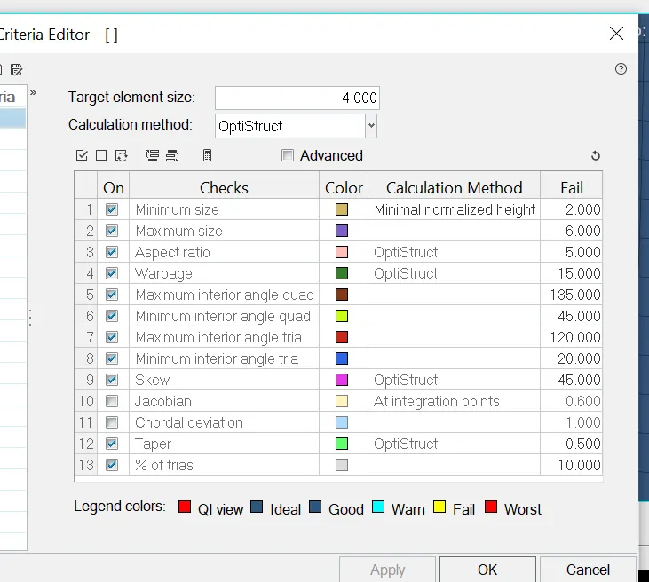
Target Element Length = 4mm
| S.N | Quality Criteria | Value |
| 1 | Aspect Ratio | 5 |
| 2 | Skewness | 45 |
| 3 | Warping | 15 |
| 4 | Taper | 0.5 |
| 5 | Min. Length | 2mm |
| 6 | Max. Length | 6mm |
| 7 | Min angle Quad | 45 |
| 8 | Max angle Quad | 135 |
| 9 | Min angle Tria | 20 |
| 10 | Max angle Tria | 120 |
| 10 | Tria % | 10 |
ABSTRACT:
- Geometry cleanup of the car side door model
- Extraction of mid surface by manually
- Perform the 2D mesh on the nid surface
- Clearing the element failure as per quality criteria
- Assigning the thickness and converting shell elements to solid elements
PROCEDURE:
GEOMETRY CLEANUP:
- Import the geometry in optistruct profile.
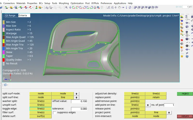
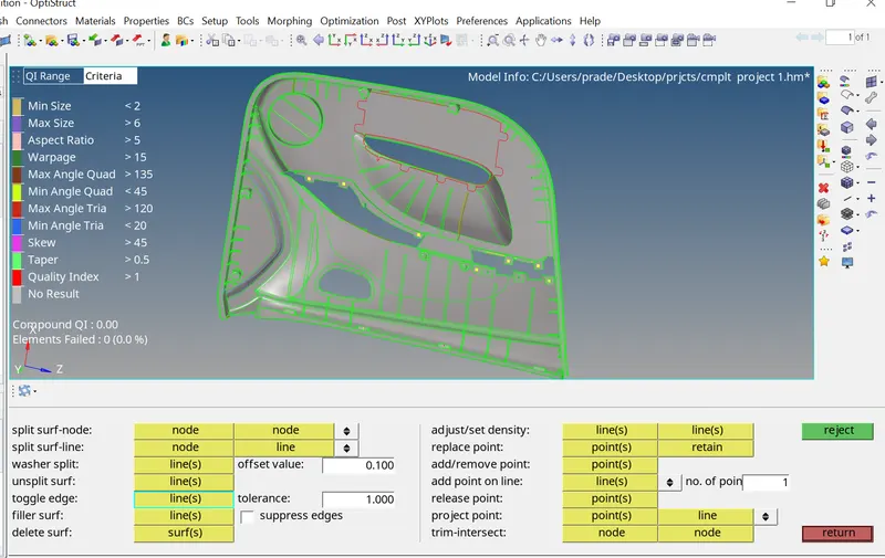
- Cleanup the geometry. and toggle the lines and create a cunstruction line for convinent for extract the mid surface
MIDSURFACE EXTRACTION:
- Extract the mid surface by manually go to srface edit in geometry panel select the surface click on offset check vector normal hit on offset button than i would get midsurface of the specified part of the comoponent.
- Before offset mention the off set value of the part. offset value is off of the thickness of the specified part
- Geometry > surace edit > offset
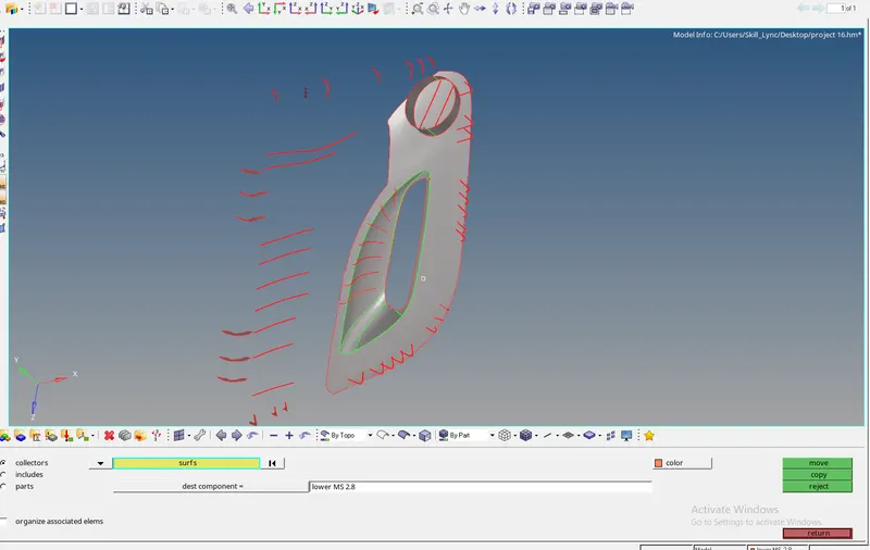
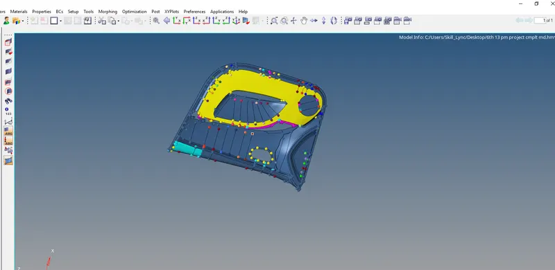
- Create the components based on the thicnes. after the offset move the mid surfaces reagarting to mention components
tools > oganice > collectors > surfacea > move
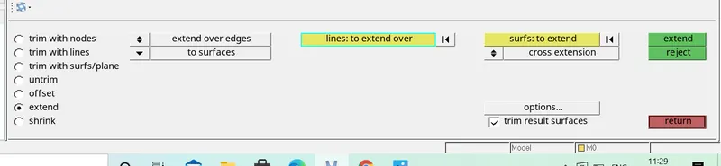
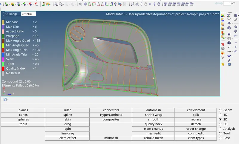
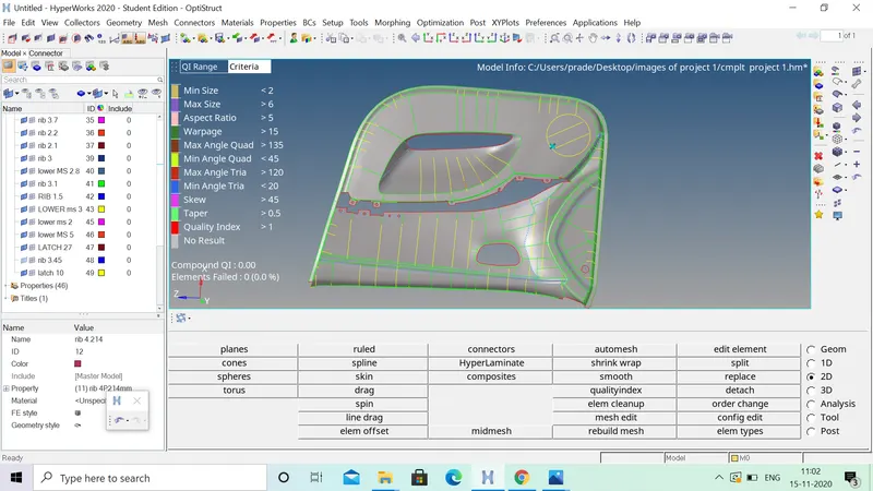
- There is a gap between the ribs and lower mid surface. extend the ribs to lower mid
surface edit > extend > lines > surface > etend
UPLOAD CRITERIAFILE:
- Fil the criteria file settings. go to preferences and click on the criteria file settings give the values regarding to given quality criteria
CLEANUP THE MIDSURFACE $ CONSTRUCTION THE LINES:
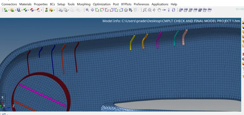
- After extract the mid surface of the car side door model. create a construction lines on mid surface to convient for the doing mesh
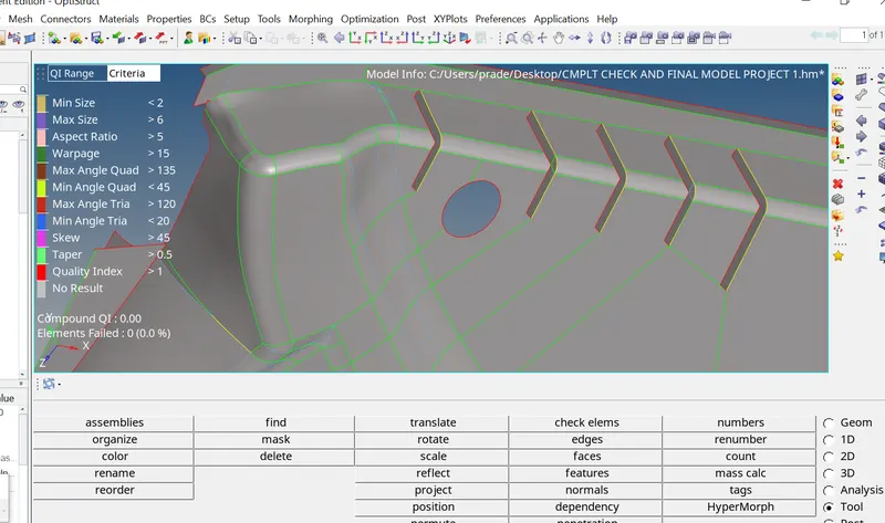
PIC:CONSTRUCTING LINES
EXTENDING THE RIBS:
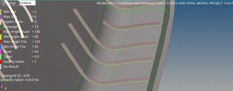
- From parageometry etracract the ribs are extraccted with using manual midsurface
GEOM > SURFACE EDIT > OFFSET > VECTORNORMAL > OFFSET
- These mid surface of the ribs extend to the surface
GEOM > SURFACE EDIT > EXTEND

- Go to surface edit in geometry and click on the extend slect extend over edges than sekect the mid of the rib lines to extend over end select surface to extend.than hit on exend ribs are extend as shown in pic
MESING:
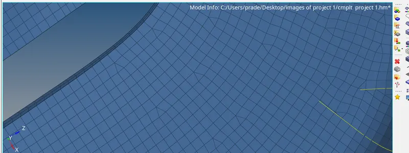
- While doing mesh try to reduce tria concentration on the corners and remove the trias at edges and fillets
- After meshing i wolud get some failed elements like maximum length, warpages and miximum angle elements
- clear all the failed elements and reduce tria concentratin in mesh
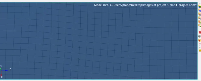
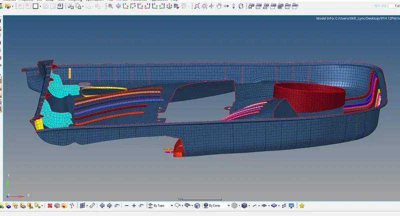
- Below mentioned pics shows the mesh at plaine surface and cornr surfaces
- drag the tria elements as possible
CLEARING FAILED ELEMENTS:
- Clear the failed elements are many ways based on the type of failure like warpage issue , element length,angleand skew
- these failed elements clear with uusing cleanup tools like elemnt opyimization, translate drag element

CHECK ELEMENT QUALITY:
- After completing the mesh check the quality of the mesh. select F10 key from keybord its shortcut key for ceck quality of the mesh give the values from the quality criteria file and check one by one
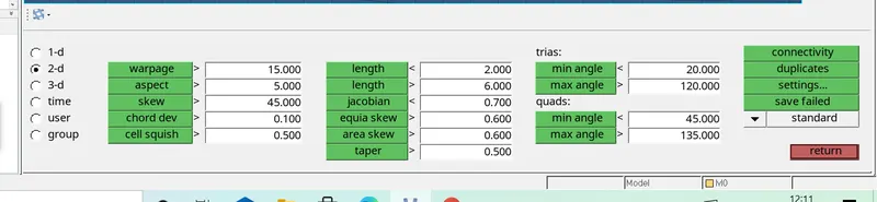
- If u get any failed elements save failed elements and mask and select the lements click on retrive than reverse the elements and clear the failed elements
FIND EDGES:
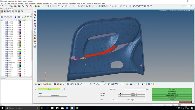
- After completion of meshing check element quality than find the free edges in the mesh
TOOLS > ELEMENTS > EDGES

- I Would get some free edges. than will go to tools select edges and elements displayed prview equailence than click on equalence . but i will get some free edges these edges clearing using with replace node option .than join one element with other element
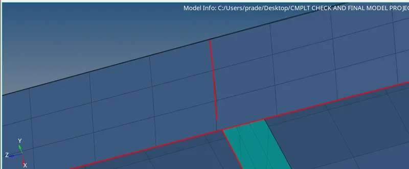
PIC : FREE EDGES
- After cleared edges total mesh dont have any free edges as shown in the below figures
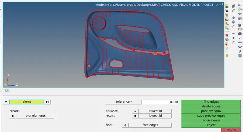
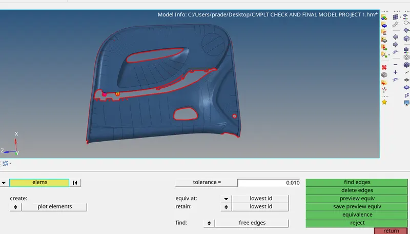
PIC : NO FREE EDGES IN THE MODEL
CREATE COMPONENTS AND TEIR PROPERTIES:
- After completion of meshing create the properties of the all the before created components based on the thickness
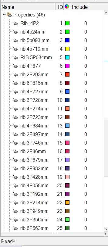
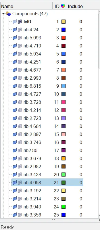
- Assign the proprties of all the components
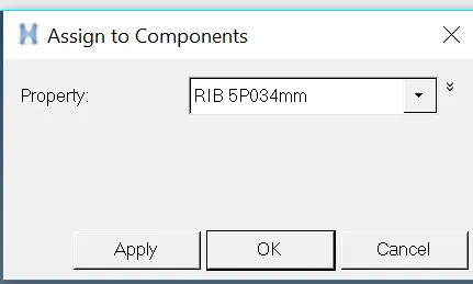
- Left click on the component >assign > apply
- Assign the thickness and convert the shell elements to solid elements
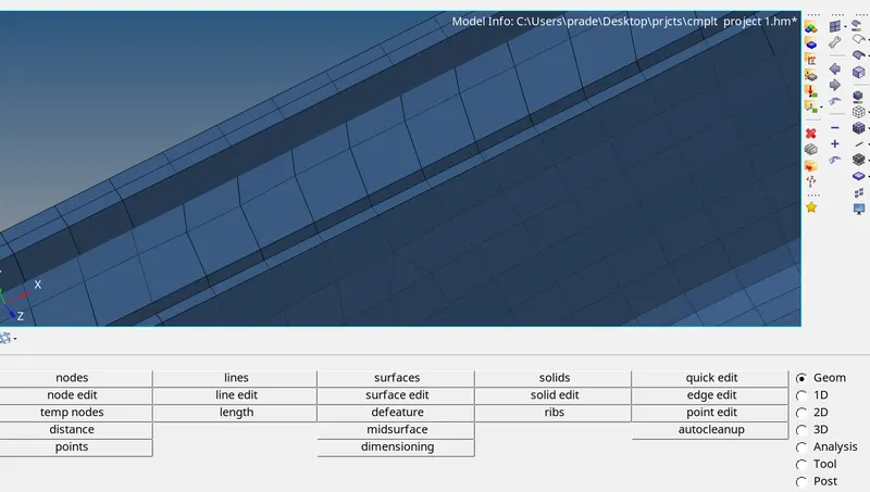
RESULT: THE MID SURFACE,MESH AND THICKNESS ARE ASIGNED SIDE DOOR INNER PANEL MODEL.
THIS CHALLANGE TEACHES ME SOMETHING NEW
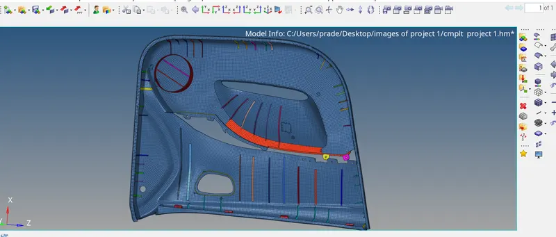
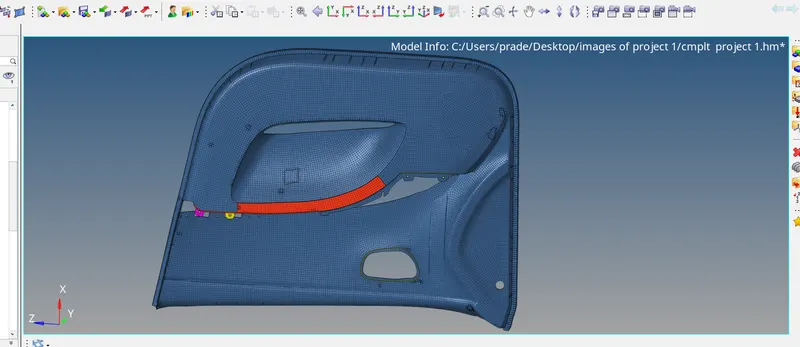
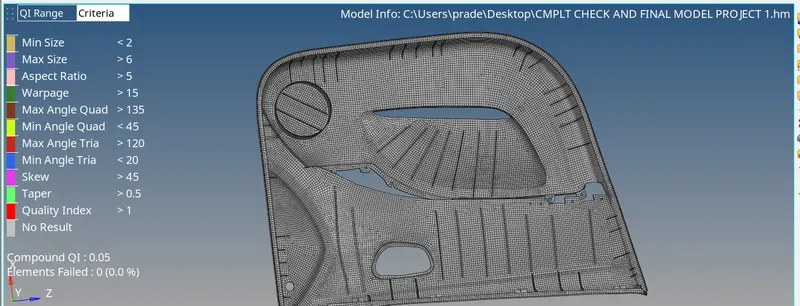
PIC: FINAL THICKENED MODEL WITHOUT ERRORS