Week -2
WEEK-2
OBJECTIVE:
1. Make a Simulink model of doorbell using with solenoid
In the above arrangement, when the switch is closed the electromagnet receives electrical power from the battery and pulls the metal arm to hit the bell producing sound.
Create a situation where the switch is closed for 2 seconds and then released. Observe the physical movement of the plunger.
2.Use a thermistor to sense the temperature of a heater & turn on or turn off the fan as per the below conditions:
Temperature source: 20 °C from 0 to 10 seconds, 27 °C from 10 to 30 seconds, 23 °C from 30 to 50 seconds
Fan conditions: ON if the temperature above 25 °C, OFF otherwise
THEORY:
SOLENOID :
the solenoid is a device comprised of a coil of wire, the housing, and a moveable plunger (armature). When an electrical current is introduced, a magnetic field forms around the coil which draws the plunger in. More simply, a solenoid converts electrical energy into mechanical work.
Electromagnets are the magnets like solenoids created with insulating copper wire, core, and the power supply. Electromagnet's magnetic property can be controlled by switching ON/OFF the power supply or controlling the current through the coil.
DOORBELL: Below image shows the working of the electric doorbell. when the switch is on the electrical circuit is activated and it activates the solenoid which turns to hits the bell.
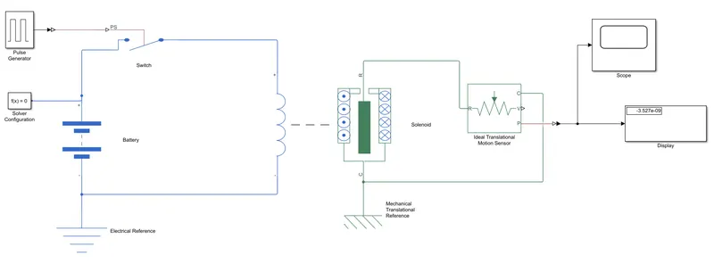
SIMULINK MODEL OF DOORBELL:
EXPLANATION:
- The battery is connected to the solenoid via sitch. the switch is connected with a pulse generator. pulse generator creates input signals when the switch is closed current flow is allowed. otherwise current flow not allowed.
- electrical reference is connected to the battery circuit.
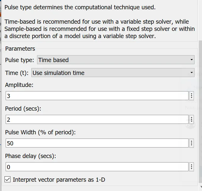
- So to give the input of pulse generator amplitude value is 3. pulse width 50%, period 2sec, phase delay0.
- Give the inputs to solenoid damping value is 5.
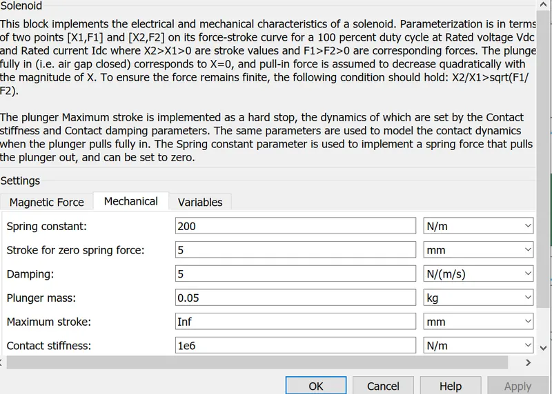
- a solenoid is connected to the motion sensor to get the appropriate position of the plunger.
- Mechanical translational motion reference sensor connected to the solenoid circuit. It represents a mechanical translational point
- scope is connected to the motion sensor to view the output.
- when we are going to run the simulation we would get an error. connect the solver error connect to the circuit to solve the error.
OUTPUT:
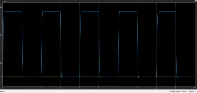
- When the pulse generator amplitude value is 3. the movement of the plunger is low and high in interval 2sec.
- Bell rings for every 2 sec in a time span of 10sec
THERMISTOR:
A thermistor is a resistance thermometer or a resistor whose resistance is dependent on temperature. The term is a combination of “thermal” and “resistor”. It is made of metallic oxides, pressed into a bead, disk, or cylindrical shape, and then encapsulated with an impermeable material such as epoxy or glass.
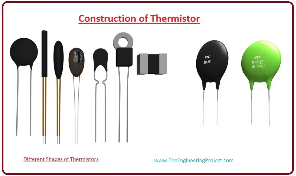
There are two types of thermistors one is NTC and the second is PTC.
NTC(negative temperature coefficient) are mostly used thermistors When temperature increases, resistance will be decreased. temperature decreases, resistance will be increased.
BLOCKS ARE USED:
Signal builder: use the signal builder to create and access the signal builder blocks.
Battery: battery is used to supply voltage to the thermistor
Thermistor: The block represents the NTC THERMISTOR.
Resistor: The relationship between voltage and current is V=IR. Resistors have positive and negative signs. current flowing positive to negative.
Controlled temperature source: This block represents an ideal energy source in the thermal network that can maintain the controlled temperature differences regardless of heat flow rate.
Temperature source: This block represents an ideal energy source in the thermal network that can maintain constant absolute temperature regardless of heat flow rate.
Voltage sensor: this block represents a voltage sensor. it's used for measuring Voltage.
electrical reference: electrical reference port connected to the ground. A model must contain at least one electrical port.
switch: The switch block Is passes through one point the second input is the control input.
EXPLANATION:
SIMULINK MODEL:
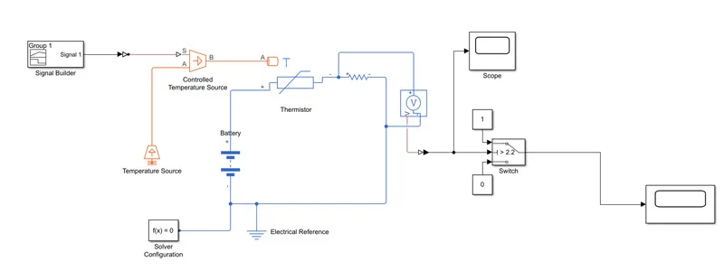
- Battery connected to the thermistor.current flow through the positive signs of the resistor.
- use a signal builder to create access to the signals connected with controlled temperature.
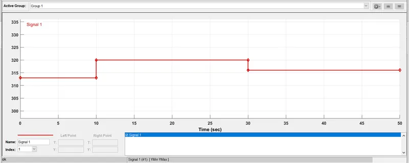
- give inputs to signal builder based on the given inputs
Temperature source: 20 °C from 0 to 10 seconds, 27 °C from 10 to 30 seconds, 23 °C from 30 to 50 seconds
Fan conditions: ON if the temperature above 25 °C, OFF otherwise
- electrical reference connected with the circuit. It must contain blocks.
- voltage sensor connects with a circuit to measure the voltage.
- now the switch has three ports. above threshold voltage connect to the middle port. The other 2 ports are connected with constant blocks 1 and 0switch on or off respectively.
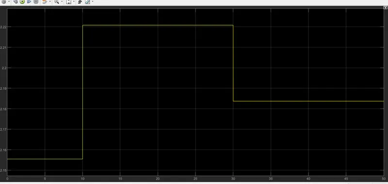
- we will provide the input for switch 22.5 if the condition is ON if the temperature above 25 °C, OFF otherwis
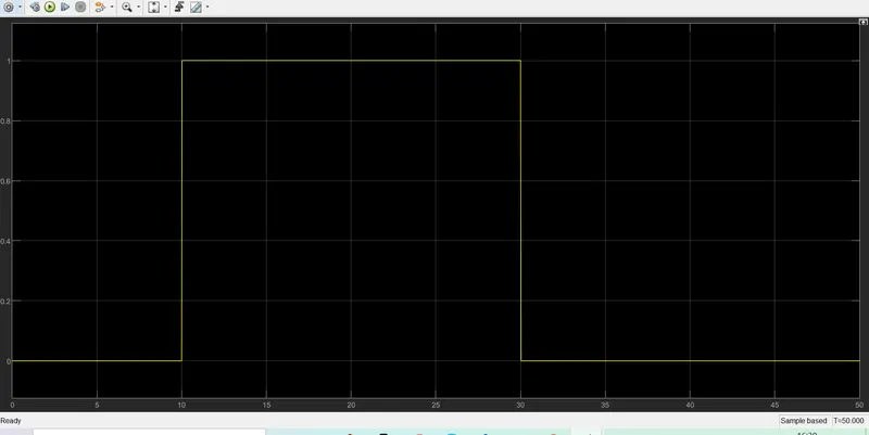
OUTPUT: From below graph
Temperature source: 20 °C from 0 to 10 seconds switch is off, 27 °C from 10 to 30 seconds switch is on, 23 °C from 30 to 50 seconds switch off.