Week - 4
WEEK-4
OBJECTIVE:
- Implement control logic of a “washing machine” using Stateflow as per given sequence:
- If the power supply is available, the system gets activated
- If the Water supply is not available, stop the process & indicate through LED
- Soaking time should be 200s followed by Washing time of 100s.
- Then rinsing happens for next 20s & dryer runs for 50s
After all the processes have completed turn on the finished LED
2. Make a Simulink chart for the “Gear shift” logic as per the below conditions:
Speed Range(km) Gear
0 to 15 1
16 to 25 2
26 to 40 3
41 to 60 4
Above 61 5
Give speed input while the simulation is running & display the gear number.
Control logic of a “washing machine” using Stateflow:
WORKING PRINCIPLE OF WASHING MACHINE:
Explanation: The working principle of a washing machine is centrifugation. Centrifugation is a separation process that uses the action of centrifugal force to promote accelerated settling of particles in a solid-liquid mixture. The washing machine consists of a centrifuge for this purpose.
Inside the washing machine, there are few processes are carried out-in successive period of time. they are
- soaking
- washing
- rinsing
- drying
SIMULINK MODEL:
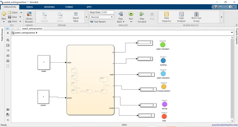
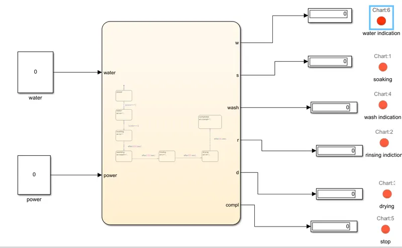
Washing machine in working condition
EXPLANATION:
BLOCKS ARE USED:
CHART: Chart is used to implement control logic with a finite state machine.
Lamp: The lamp block displays a color indicating the value input signal.
PROCEDURE:
- Input values of this model are water and power
- 1 indicates power is on and supplying water flow. 0 indicates power is off and water supply is off.
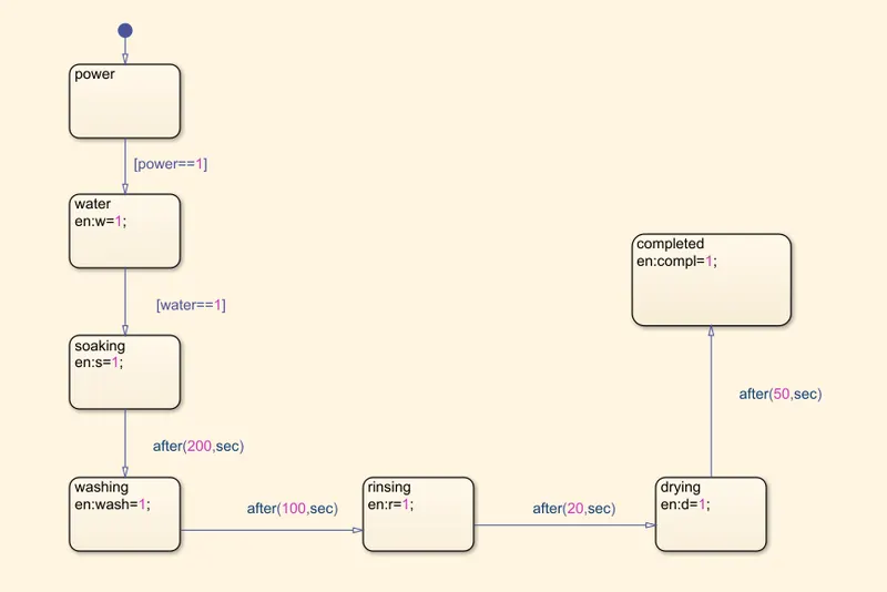
- implement control logic in the chart. check power and water to give condition power==1.
- soaking time 0 to 200 sec to give input on soaking
- after 200sec give 100sec for washing.
- then give 20 sec for rinsing and 50 sec give input for drying
Given data:
- soaking-200sec
- washing-100sec
- rinsing-20sec
- drying-50sec
- completed
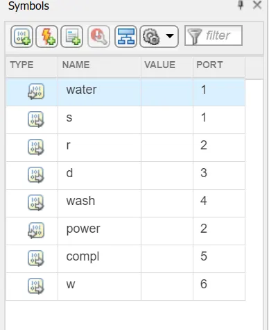
- give water and power as inputs and socking, washing, rinsing, drying given as outputs.
- Lamps are used to working given commands in washing machines that indicate different colors.
- The washing machine was not working all the lamps shows in red color.
“Gear shift”:
The word shifting describes something that is taking a new direction either physically or in thought. If you've recently decided that the earth may be round, you are shifting from a flat-Earth viewpoint to a round-Earth one. Shifting can be used in several senses, but the constant in all of them is change and movement.
Simulink chart for the “Gear shift” logic:

Given conditions:
Speed Range(kmph) Gear
0 to 15 1
16 to 25 2
26 to 40 3
41 to 60 4
Above 61 5
SIMULINK MODEL:
 BLOCKS USED:
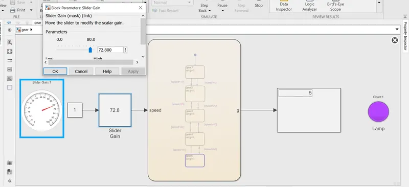
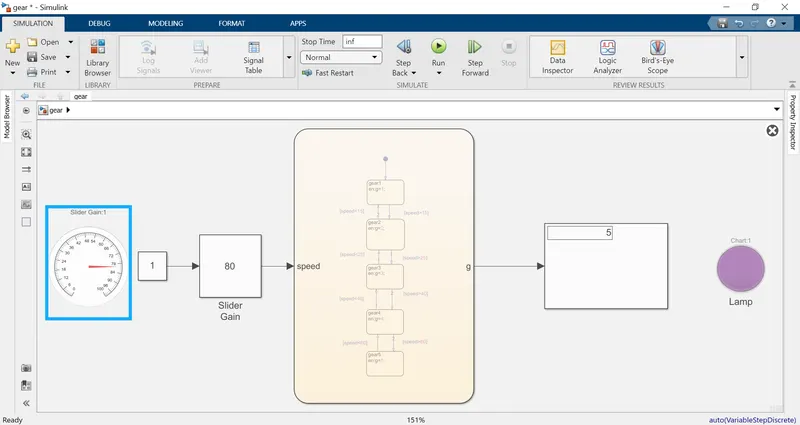
GAUGE: Gauge block displays the connected signal 0n circular scale during simulation.
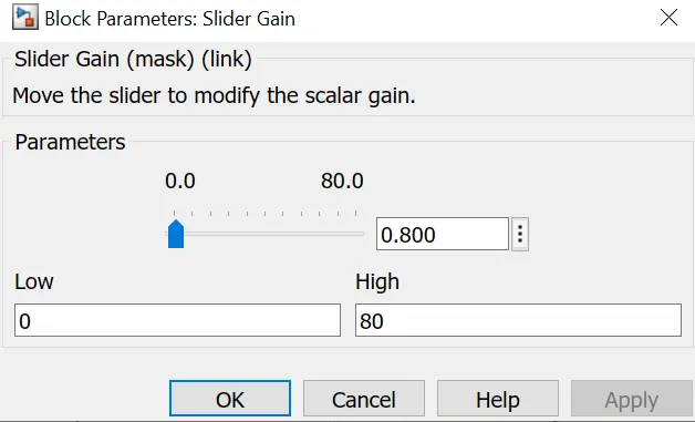
SLIDER GAIN: Slider gain performs the scalar gain that you can modify during simulation. modify the gain using slider parameter
EXPLANATION:
- As per the question gears are arranged 0 to 15 speed in first gear. 16 to25 2nd gear, 26 to 40 in 3rd gear, 41 to 60 in 4th gear above 60 speed in 5th gear chart as designed such a way.
- drag the gauge from simulink library and drag costabt block, slider gain connected with gauge it shows the spped
- slider gain changes the speed.
- display shows the wich gear on going based on the speed.
- lamp is connected to output. lamp displays the green colour in first gear and each gear will produce individual color.

- give speed as input. gear as output
- For the first gear,0 to 15 kmph
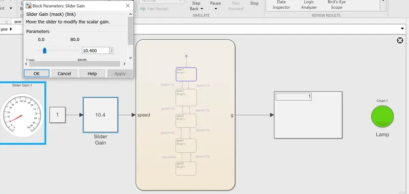
- for the second gear, 16 to 25kmph
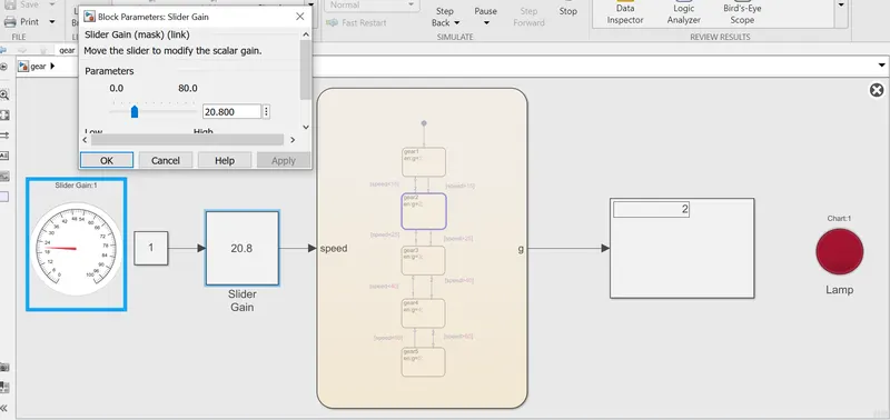
- For the third gear, 26 to 40kmph
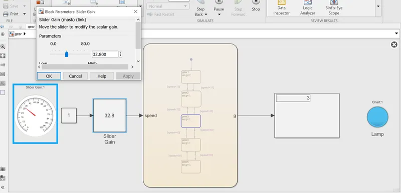
- for the 4th gear,41 to 60kmph
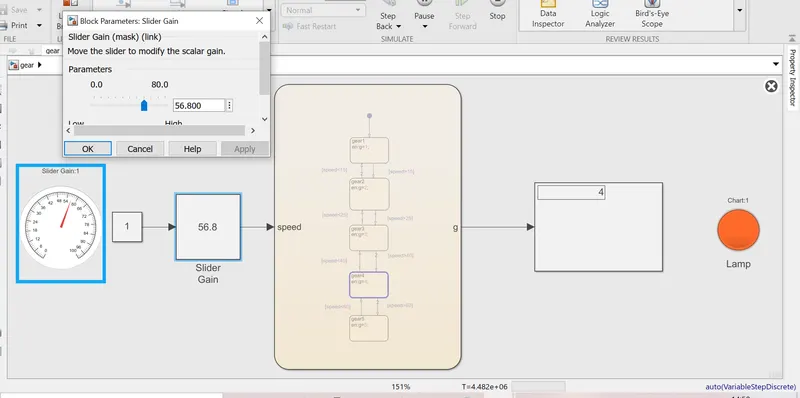
- For the 5th gear, above 60kmph.