Week 9 - Project - Master Section Development
AIM:
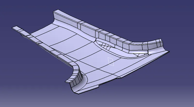
To create the Plastic design and the Engineering features from the Master Sections and generate the Draft Analysis for the given B Pillar Class A model and Final Component.
PROCEDURE:
1.Check for any openings in the given model Door Applique by using BOUNDARY. In BOUNDARY > select edges - select the surface to create the boundary at the openings.
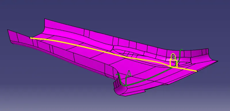
2.Create the Tooling Axis using the Bisecting Method.
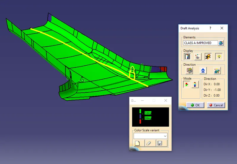
3.To create the Tooling Axis, extract the Master sections 1&2 as shown and by using Line Definition: Line Type - Bisecting, Line 1 - select the extracted line and Line 2 - select the extracted parallel line Point - Select the point created in between using Point definition and the line which gets created will be the Main Tooling Axis(Yellow).
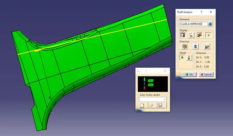
4.Generate the Draft Analysis on the Class A surface.
CREATION OF FLANGES ON CLASS A SURFACE:
5.To create the Flanges for Class A surface, Extract the Boundary of Class A on one side using the Multi Extract option and then extract the surface near the flange using the Multi Extract option as shown.
6.Use the Curve smooth option to smooth the extracted boundary and then using the Sweep option create the Flange by Sweep: Profile type - 2, Subtype - with draft direction, Guide curve - Boundary and Reference surface - extracted surface and Angle - 3 degrees.
7.Create the plane at the Master section 2 as shown and intersect with the Class A and Swept surface. Make the Swept surface parallel to the Master section Flange by changing the draft angle in Sweep as shown.
8.Compare with the Master section and Class A for the Flange, change as per the Master section and offset the Flange of 2mm for Class A as shown. Trim the offset Flange with Class A.Same procedure to create the Flange on the other side. Trim the Flange with Class A.
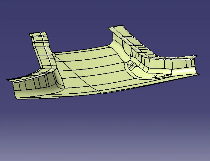
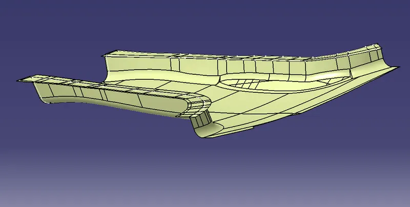
9.While offsetting the Flange it may create a patch on the surface. So fill the surface by creating a Spline and use Multi-Section Surface.
10.Fillet the edges of the trimmed surface.
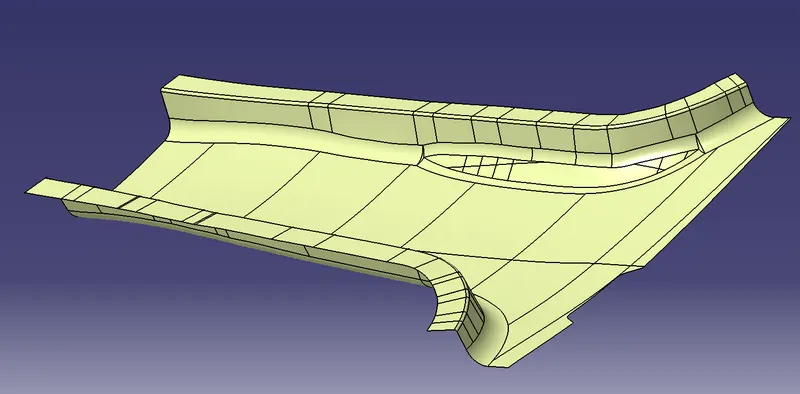
CREATION OF B SURFACE WITH FLANGES:
11.Offset the Class A surface to 2mm to create the B Surface and if any patches are created, fill the surface by creating a Spline and use Multi Sectional surface.
12.Offset the Flanges to 2mm to trim it with the B Surface. Extrapolate the B Surface if the Flanges were not intersecting with the B Surface.
13.Fillet the trimmed edges with the dimensions from the Master sections.
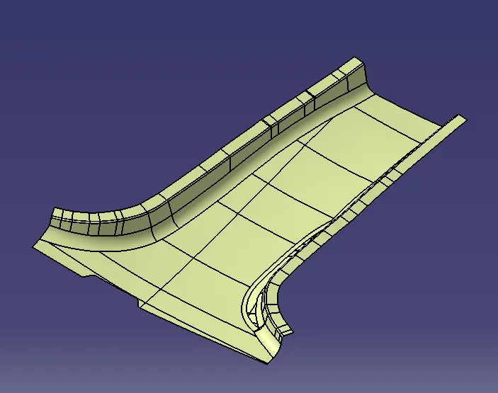
CREATING C SURFACE:
14.Using the Multi Extract option, extract the boundaries of the Class A surface after creating the flanges as shown.
15.Using the Sweep option: Profile type - 2, Subtype - with draft direction, Guide curve - Boundary and Reference surface - extracted surface and Angle - 3 degrees and give the draft direction towards outside of Class A, create C Surface.
16.Use the Multi-Section Surface at the curvature to create the surface as the sweep option cannot perform the operation.
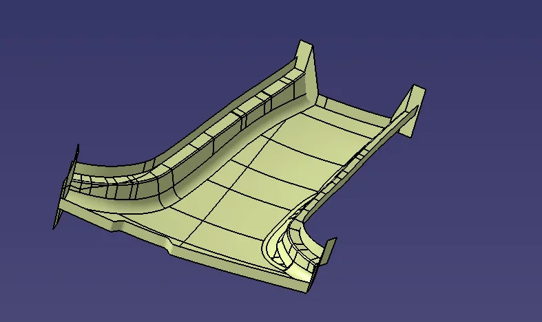
17.Extrapolate the A Surface if the C Surface is not intersecting with the A Surface.
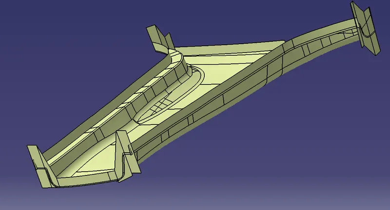
18.After the Class A surface intersecting with the Class C surface, join the Class A and Class C surface by the Join option and then trim it with the B surface.
19.In Part Design, fill the surface body with the solid using Close surface.
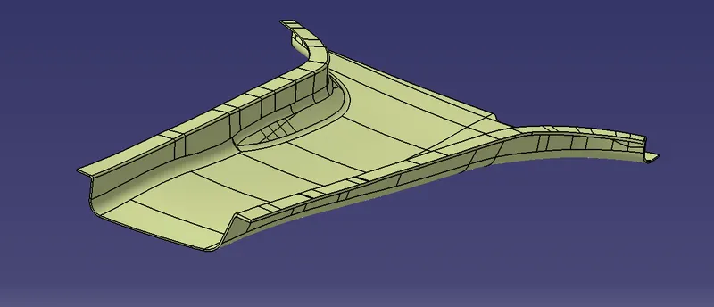
CREATING DOG HOUSE:
20.From the given Master section 1&2, Project the Master section 1 and extract the dog house projection.
21.Create a point at the center on the inner line by Point definition as shown and create a plane in with reference to the point in ZY plane and then draw the sketch as like the dog house and extrude the inner lines from the sketch using Extrude option: Profile - Line and Direction.
22.Create a plane with reference to the point in XY plane and extract the Master section 2 and Project the Master section 2 and extract the dog house projection to create the front wall and back wall and then trim the surfaces to create the dog house surface as shown.
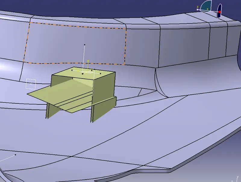
23.Thicken the extruded surface by using the Thicken option in the Part body.
24.Split the Dog House at the front with the wall in Part body.
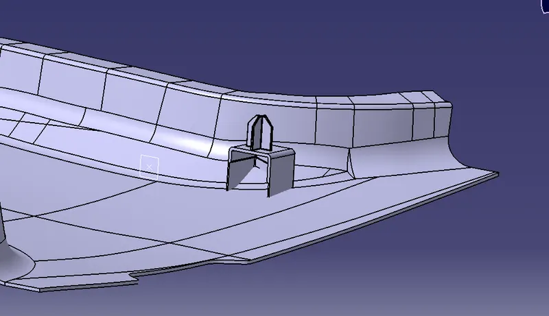
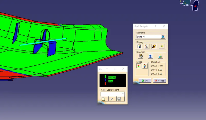
25.Draft the inner walls of the Dog house with 0.45 degrees by using the Draft option.
26.Now create the inner trim for the Dog House by offsetting the side walls to 1.2mm as the ‘C’ should be 40% to the Main wall thickness and offset the B surface in the region of the dog house to 3mm distance upwards as the ‘B’ distance from the B Surface is 3-6mm for Dog House.
27.Now intersects the offset surface with the back wall to create the feature of B surface as shown and extrude the line and then trim with the sidewall and then offset the trim to 1.2mm inside as shown.
28.Fillet the edges of the trim to the specified radius. Split the Part body of Dog House with the offset Feature trim in the Part body.
29.Fillet the Dog House of radius 1mm inside and 3mm outside.
30.Create the tooling axis for Lifter using the ZY plane(Blue).
CREATING LOCATOR:
31.Project the lines of the Master sections 1&2 to create the limits of the locator onto the plane of ZX and then draw the sketch for locators and then Pad it in the Part body to a height of 20mm as shown.
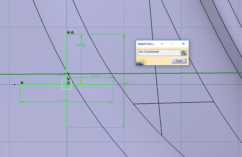
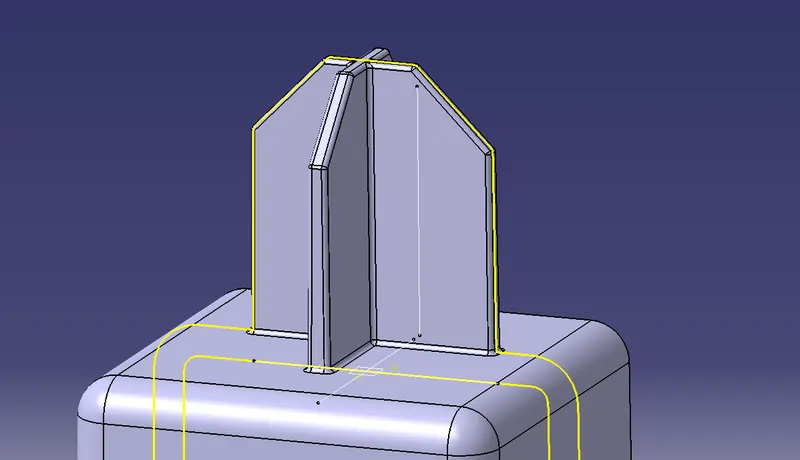
32.Draft the faces and Chamfer the edges at the top and Fillet the edges. Union trim the Dog house and with the part body and union trim the Locator with the Dog house.
CREATING RIBS:
33.Create a sketch on the ZX plane to create ribs. Maintain the distance of 50mm in between the ribs. Extrude the sketch and thicken it to 0.4 times the Main thickness.
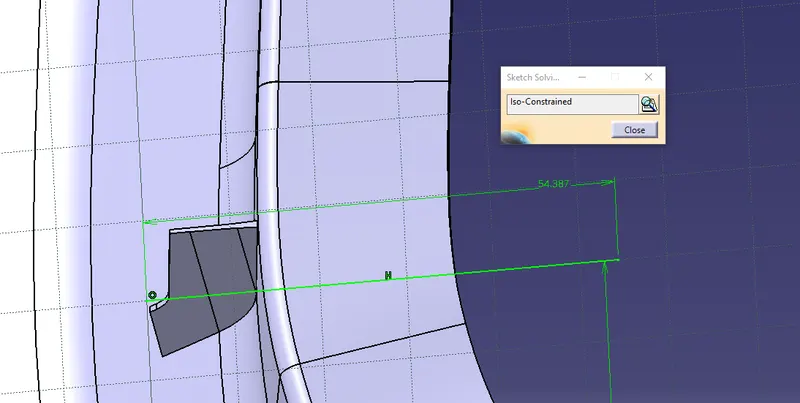
34.Translate the ribs with a 50mm distance in between on both sides. Split the ribs with Class A and 10mm offset surface of Class B surface. Union trims the ribs with the Main part body. Draft the ribs and Fillet the edges.
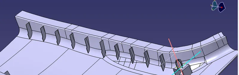
35.Generate the Draft Analysis on the Part body.
B PILLER DRAFT ANALYSIS:
1.Open the Draft analysis by Insert > Analysis > Feature Draft Analysis.
2.Select the Compass - Direction in Draft Analysis and align it to the Tooling Axis and then lock it
3.After locking it a cross symbol will occur at the pointer, select the surface and the surface selected turns into green.
4.In Draft Analysis 2 box, select the green column to change the draft angle to 3 degrees.
5.The color should be green in color
- THE NOMINAL DRFT ANGLE CONSIDERED AS 3deg.
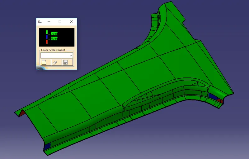
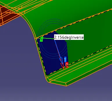
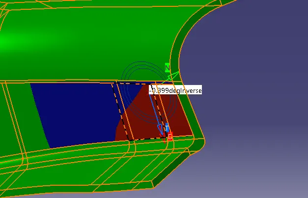
Minimum value at this area is 2.15deg Minimum value at this area is -0.89deg
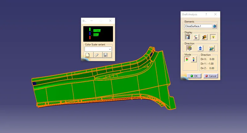
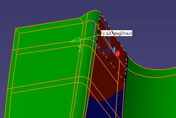
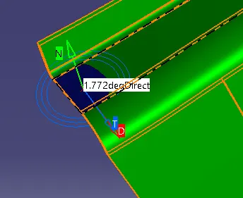
The minimum value at this area is -1.6deg Minimum value at this area is 1.7deg
RESULT:
Created the Plastic design and the Engineering features from the Master Sections and generated the Draft Analysis for the given B Pillar Class A model and Final Component.
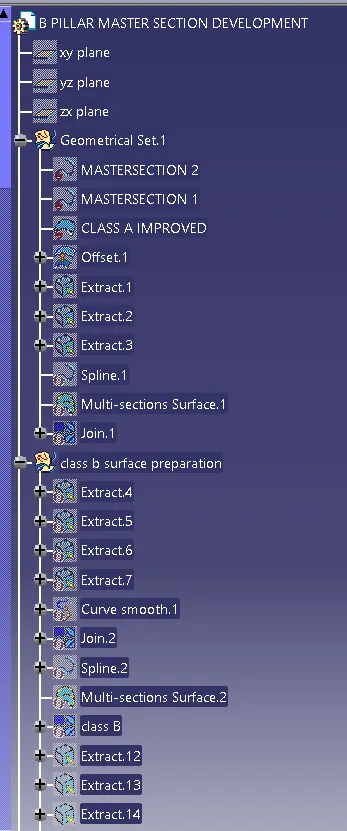
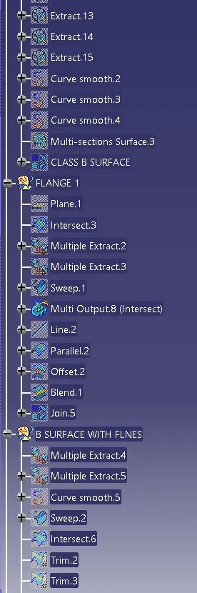
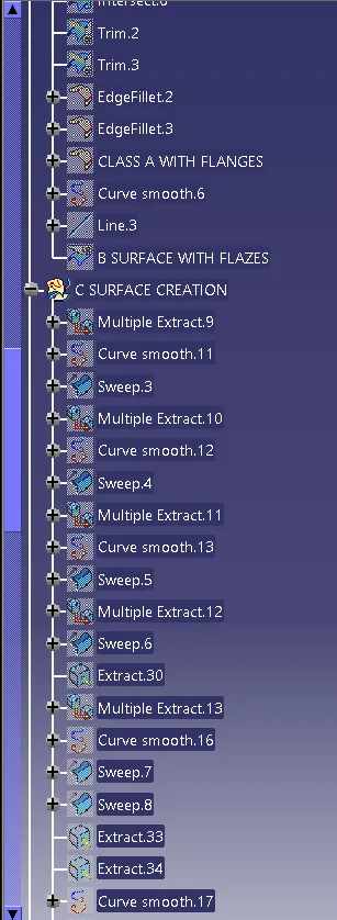
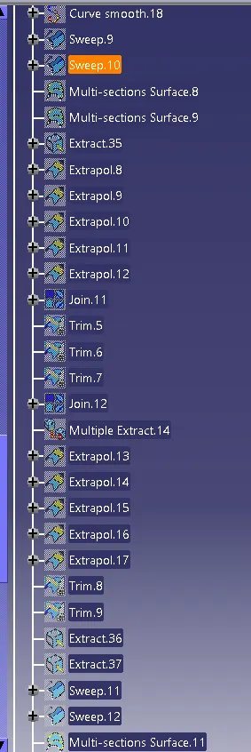
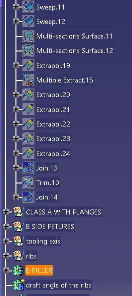
CONSTRUCTION TREE: