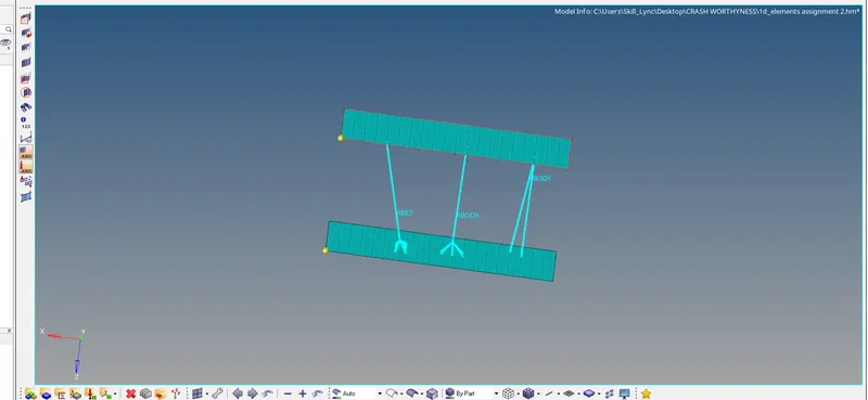
Assignment 2
AIM: SOLUTIONS OF THE ABOVE QUSTIONS
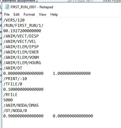
4. CHANGE THE RUN TIME IN ENGINE FILE
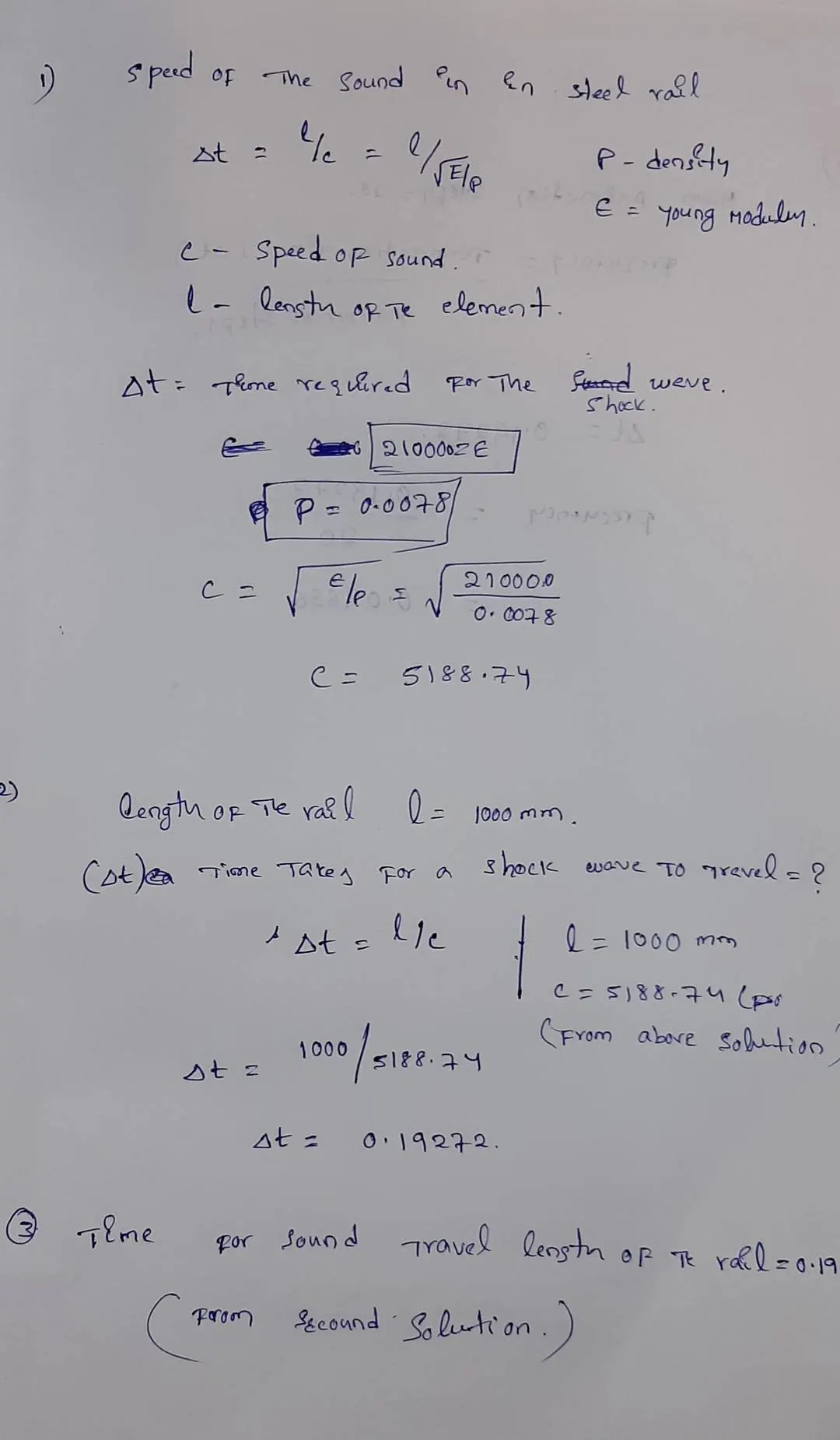
termination time is stress wave can moving from one end of the rail to the other during impact -this will require a termination time equal to the time it takes for the sound to travel the length of the rail.
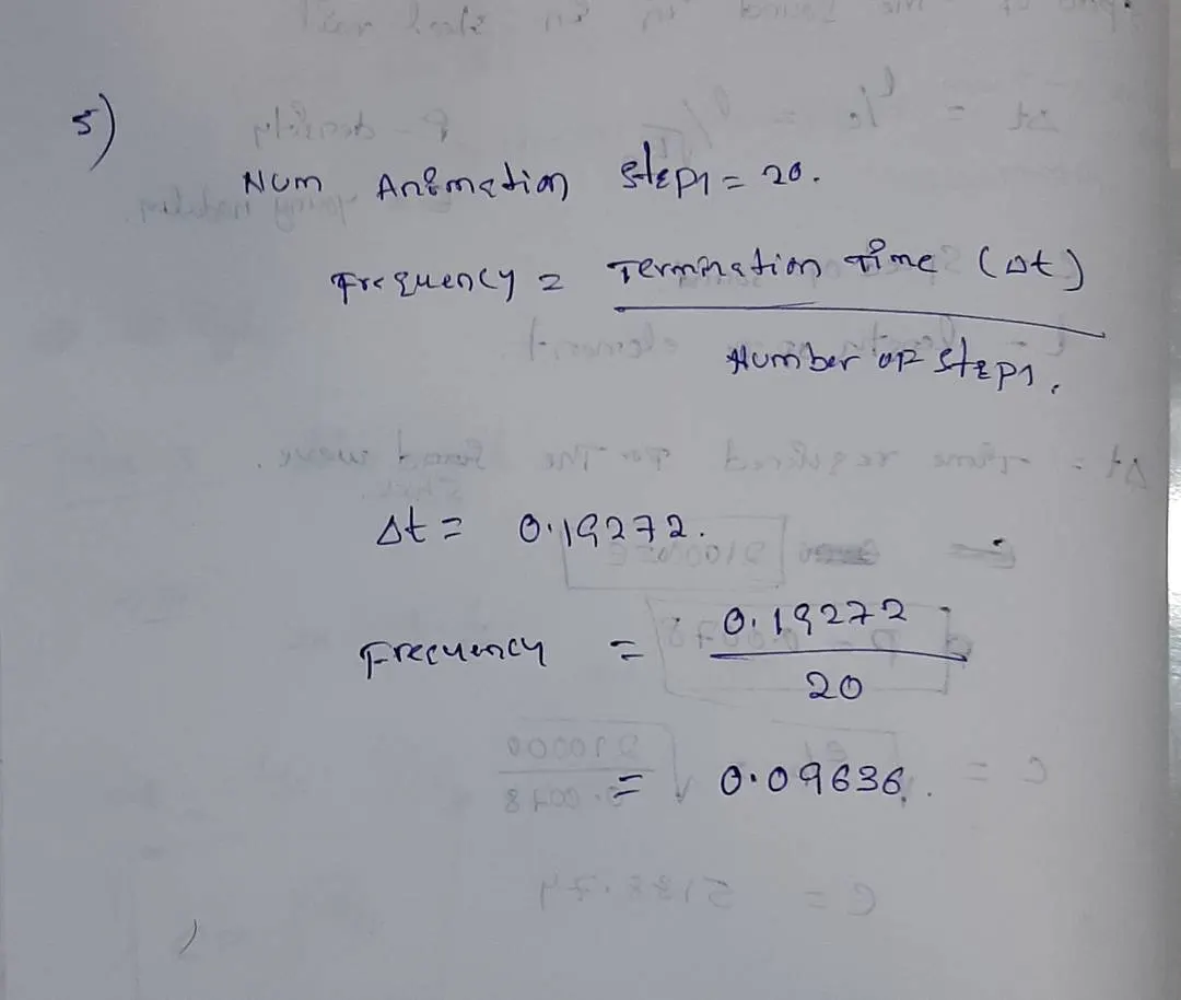
5.
.
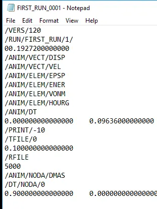
6.Change /print -10.
7.
AIM: Create Hexamesh of the armbracket
OBJECTIBE:
- Repeat class examples and, maintain the quality.
- Target tet size=5mm,hex size=10mm,tet collapse=0.15.
PROCEDURE:
- opening the model in radious file
- switch on the base remaing arm curve , arm straight and boss switched off
- select the one surface of the boss and genarate 2D mesh with only quards
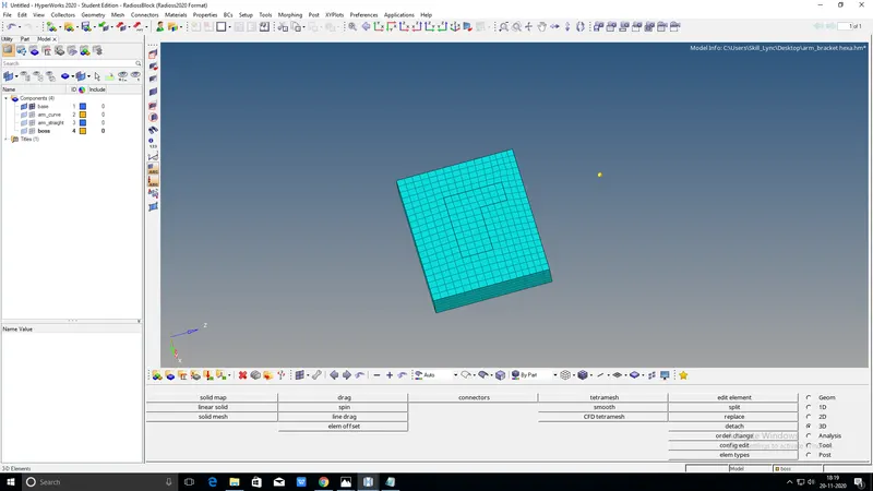
- after mesh with one part for create hexa mesh go to 3D and select element offset select solid layers than select elemnts give the number of layer 5 and total thickness 25 select the select the surfaces for the referance to create hexa mesh
- Now switch on the arm curve first this component will make current hide the 3D elements
- Go to spin elements option to genarate hexa mesh on the curve surface
- before the create centre point of the curve. click on F4 from key bord its shortcut key of between the nodes select the three nodes and click on the nodes between and will get the middle pont of the curve

- After creating a mid point go to spin option select elements select elements and prefer axis and select mid point than hit on spin -
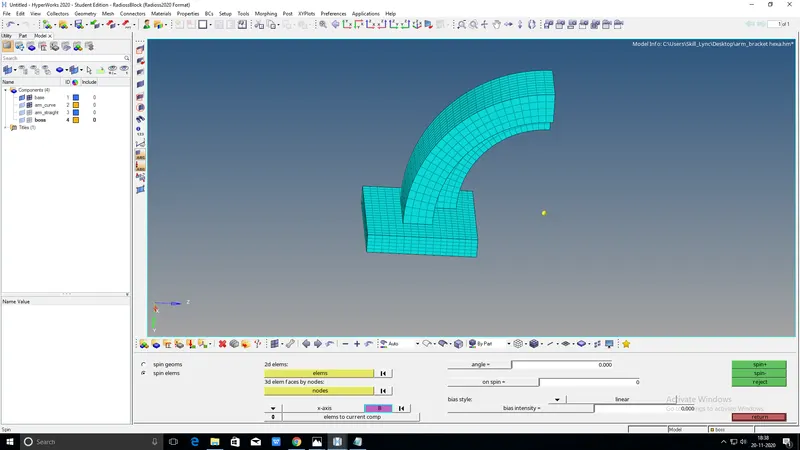
- after create hexa mesh on arm curve than swith on arm straight. create faces of the arm curve
- TOOLS > FACES > select ARM CURVE > FIND FACES
- Than create faces genarate 2D mesh on the source and destination face
- than go to 3D select LINEAR SOLID and slect N1,N2,N3 ON SOURCE elemenT and click select also destination element

- click on solid create a solid mesh on the arm straight
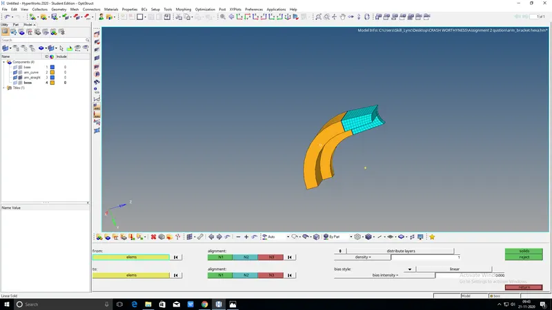
- switch on the boss create a 2D mesh on the sid urface check elements count sameras both surfaces arm straight and boss
- create a node list craete a solid map
- hexa mesh moved to solid map to boss amd delete the 2D ELEMENTS
3D> SOLID MAP > GENERAL > select elements > select NODEPATH > MESH
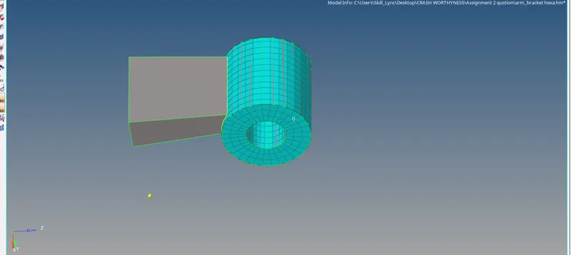
RESULT:
COMPLETED GENATRATE HEXA MESH ON THE ARM BRACKET
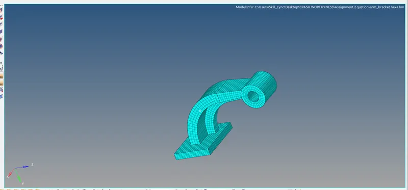
TETRA MESH
AIM: To create a tetra mesh for housing
OBJECTIVE: creat a tetra mesh of housing model with using below mentioned measurments
Tet collapse: 0.15
PROCEDURE:
1.FOR HOUSING MODEL: importb housing model in the hypermesh in iges file
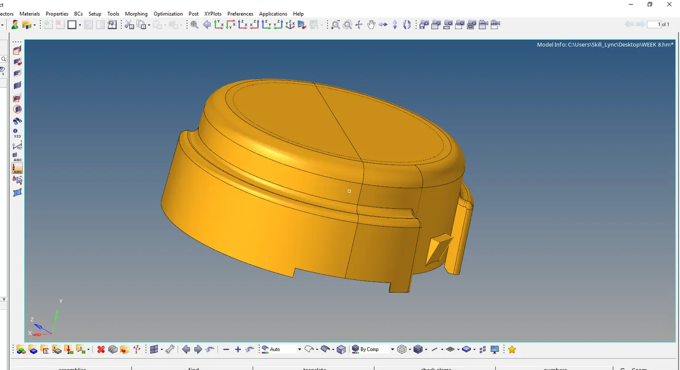
- extract the housing andtoggle the lines to convent for meshuing
- go to 2D panel and click on the automesh and select the surface .and change quards to tria for getting elemts in meshiong
- select surfaces one bye one and mesh properly and after finishing the meshing go to element check and and check the maximum and minimum lenth of the elements.
- some of the failed elemts is there.these failed elements sepereted from the mesh with using mask option
- clear the failed elements and go to the 3d mesh and given parameter values and will do 3d mesh of the hood .inthis scenario will get some failed elements and solved manually
2. creat the 3d mesh of the below component
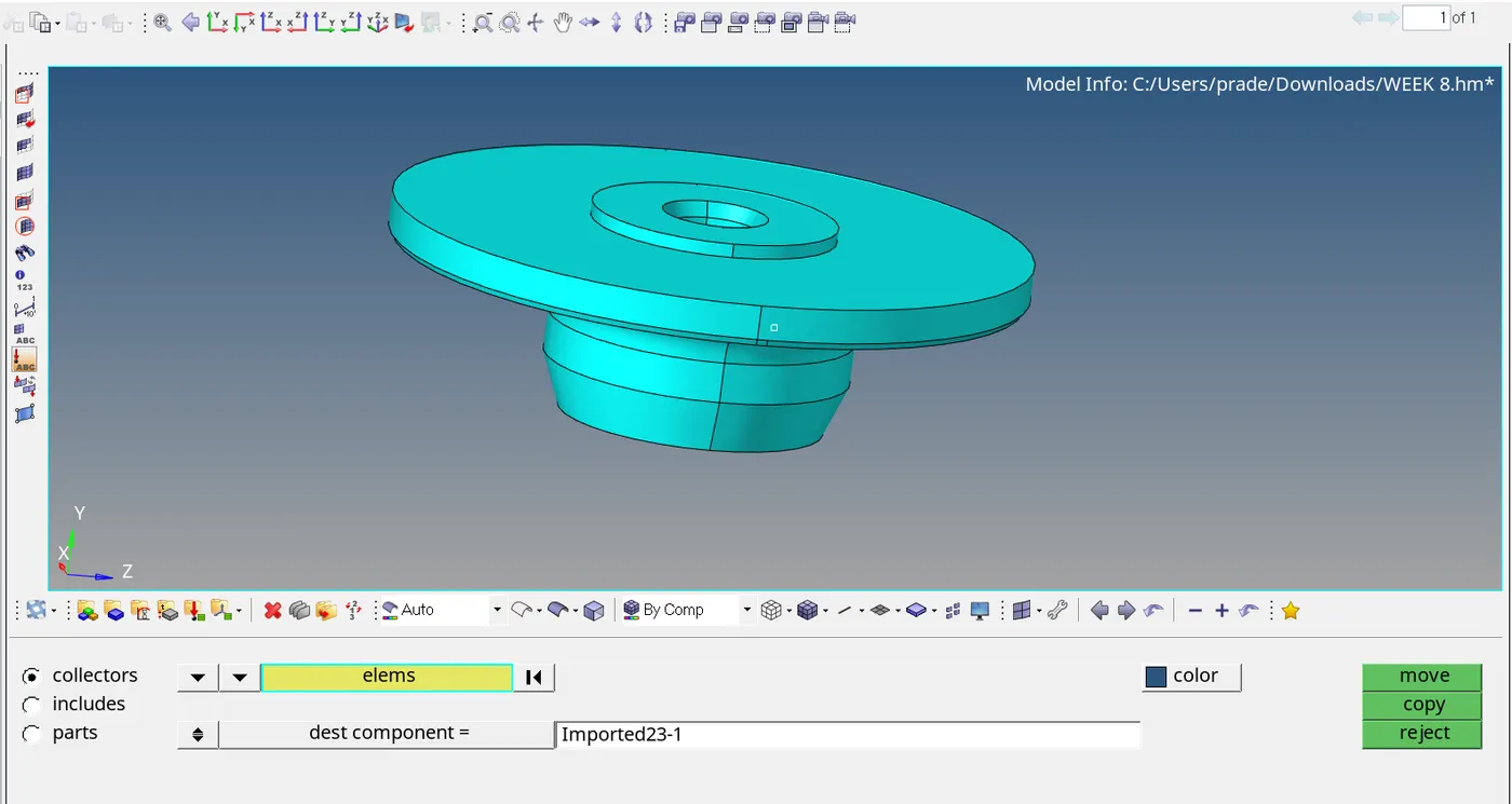
- there component also creat a 3d mesh same as the hosing model
- firs toggle the lines for getting quality mesh. and extract the mid surface of the given model and
- will do mesh properly. after will get some failed elements
- these failed elements are solved manually
- Check the tet collapse

RESULT: COPLETED THE GENARATE TETRA MESH OF THE HOUSING AND HUB COMPONENTS
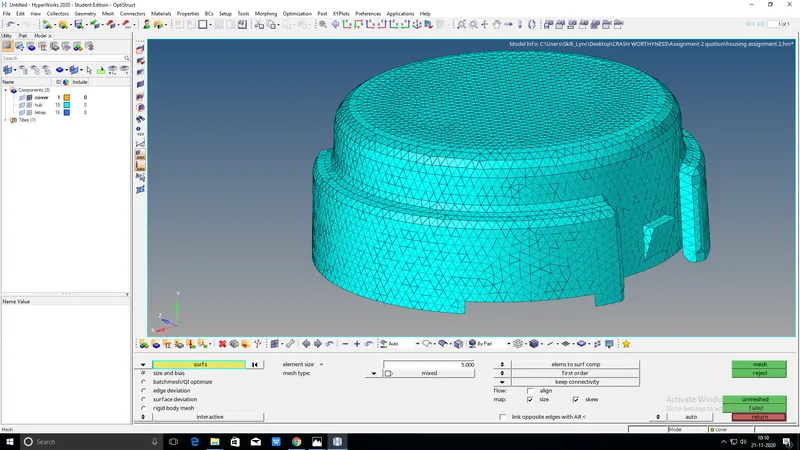
PIC: HOUSING
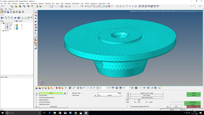
PIC:HUB
3.
AIM:CREATE A RBE 2 AND RBE 3 CONNECTIONS BETWEEN THE GEOMETRYS
PROCEDURE: go to mesdh option on to in tool bar choose create option select 1D element and select rbe 2 or rbe3
than select node on two surfaces hit on create will go to create a connections
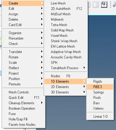
RESULT:CREATED RBE 2 AND RBE 3 CONNECTIONS