Roof challenge
ROOF DESIGN AND OPTIMIZATION
AIM:
creation of a roof ditch area the tool opening angle is only 3 degrees. For the Given Roof styling, Develop the essential flanges and reinforcements, Provide appropriate dimension and check for Draft analysis and also submit your section modulus report on the 0-Y section.
INTRODUCTION:
ROOF:
The roof of an automobile is that commodity that sits above the passenger compartment. The roof houses the vehicle as a shielding part that safeguards the occupants from sunlight, heat, rain, wind, dust, etc.
In the past roof was introduced as a cover for the passenger compartment but later on, it was also used as a luggage carrier, sunroof, and in recent past years with the introduction of the solar-paneled electric vehicle got a major boost in the automotive industry.
Roof has the following functions:
- protects from external damage
- prevents passenger and vehicle from accidents
- luggage carrier
- design of the roof also affects in giving aerodynamic shape to vehicle
Since the roof has numerous functions so the roof has to be stronger enough to withstand the damage experienced by it. To have good strength and stiffness, the roof is made with different components such as front roof rail, rear roof rail, bow roofs, etc.
HEAT DISTORTION CRITERIA:
Bow – roof prediction Formula
W = [1.73 x 10^(-3) x L] + [1.85 x 10^(-8) x (R^2)/t] + [ 1.10x10^(-3) x l] - 2.68
Judgement Condition : OK< 2.7> 3.1
Where
L = Roof Length in X-Direction[mm](Roof dimension in 0-Y)
R = Roof curvature
R = 2(Rx*Ry)/(Rx+Ry)
Rx = X curvature
Ry = Y curvature
t = Roof plate thickness [mm]
l = Bow Roof Span [mm]
Snow load Prediction formula
SNOW LOAD CRITERIA:
Qr = [Iy x t2] / [α x s x [(Rx + Ry)/2]2 x 10-8]
Note: The Qr value given over here is correct. There was a typo error in the formula given in the video.
Where
α = My x Lx2 x 10-12 , My = Y(Ly-Y)
Judgement condition = Qr ≥ 3.1
250 ≤ s ≤ 380
t = Roof plate thickness [mm]
Ly = Distance between the front and rear roof Rails on the Vehicle along with 0Y[mm]
Length of Roof panel with the center point between Roof rail Front /Rear as the reference point of the front and the rear.
Lx = Distance between the Left and Right end of the roof on the Roof BOW [mm]
Width of the roof panel exposed on the surface.
Y = Distance front Front Roof Rail to Roof BOW[mm]
s = Distance for which Roof BOW bears divided load [mm]
s = L1/2 + L2/2
Iy = Geometrical moment of inertia of Roof BOW (Y cross-section )[mm4]
Rx = Lateral direction curvature radius of roof panel Y cross-section on Roof BOW [mm]
Roof panel curvature Radius of the Length Lx in Front view
Ry = Longitudinal Direction curvature radius of the Roof panel X cross-section on Roof BOW [mm]
Roof panel X curvature radius of length s in Side view
SECTION MODULUS:
Section modulus is a geometric property for a given cross-section used in the design of beams or flexural members. Other geometric properties used in the design include an area for tension and shear, the radius of gyration for compression, and moment of inertia, and polar moment of inertia for stiffness. Any relationship between these properties is highly dependent on the shape in question.
calculate the section modulus using the formula S = I/y
There are two types of section moduli, the elastic section modulus, and the plastic section modulus.
For general design, the elastic section modulus is used, applying up to the yield point for most metals and other common materials. The elastic section modulus is defined as S = I / y
The plastic section modulus is used for materials where elastic yielding is acceptable and plastic behavior is assumed to be an acceptable limit. Designs generally strive to ultimately remain below the plastic limit to avoid permanent deformations, often comparing the plastic capacity against amplified forces or stresses.
MOMENT OF INERTIA:
The moment of inertia is defined as the quantity expressed by the body resisting angular acceleration which is the sum of the product of the mass of every particle with its square of a distance from the axis of rotation. The moment of inertia is also known as the angular mass or rotational inertia.
PROCEDURE:
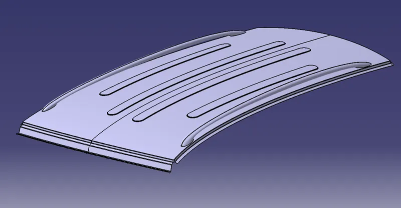
Class –A surface:
- After the file is opened, the roof part is not joined together but as the individual surfaces.
- It is also seen as the surface is perfectly symmetrical in shape which helps us to work on the half of the portion and reflect it which creates the whole roof
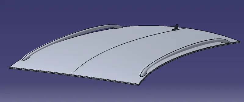
Creating the Flanges for the Roof:
- Extract the upper roof part by selecting it.
- Now, since it is a sharp corner at the end to make it smooth, use the corner option to create a cut on the edges and split it to create the smooth corner.
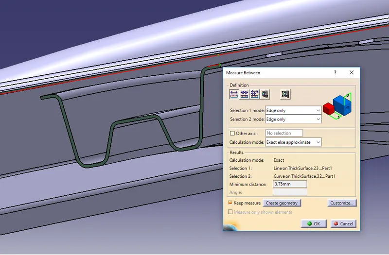
- Now select an edge and sweep it with the 3 degree draft with a length of 15mm.
- From the edge of the sweep take another sweep with the 25 degree draft of length 21.5 mm (as shown in the reference dimensions).
- Follow the same procedure with the other edges.
- Now, create the curved edges by using curves as the guide curves and the multi section surface option.
- Join the Surfaces together and give the fillets.
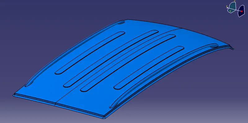
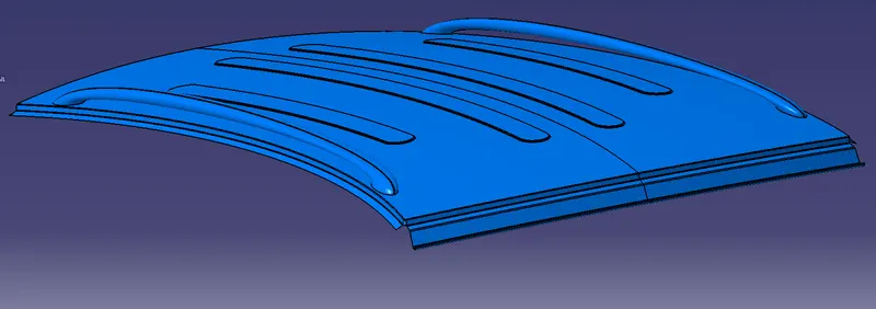
CREATING EMBOSS ON THE ROOF FOPR GIVING EXTRA STRENGTH
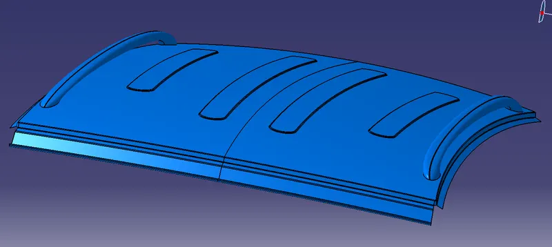
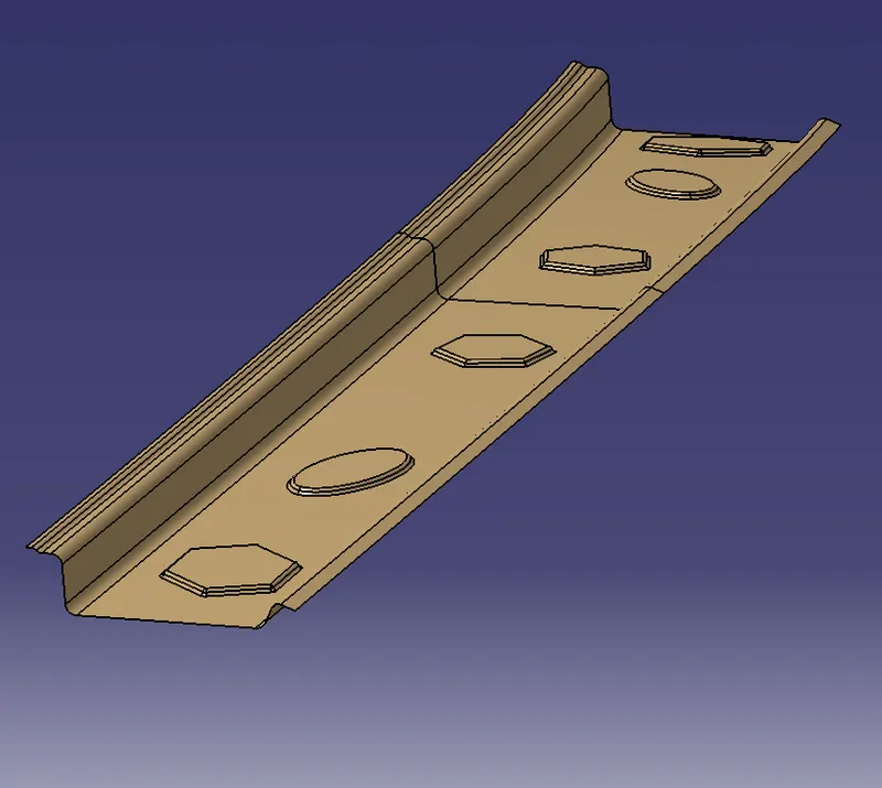
Creating the Front roof Rail:
- Offset the roof to 2.7mm and split it with a distance of 5mm.
- Similarly, create an offset of 4.7mm and cut it.
- Now create a base offset of 32mm from the roof.
- Create the respective sweeps for these offsets and trim them together.
- Give the Edge fillets to it
- Give the embosess for extra streangth
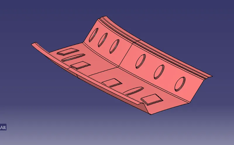
creating rear roof:
- The rear roof rail follows a similar procedure as the front roof and the values for it are given in the diagram.
- Make sure that the Rear roof has a positive draft angle.
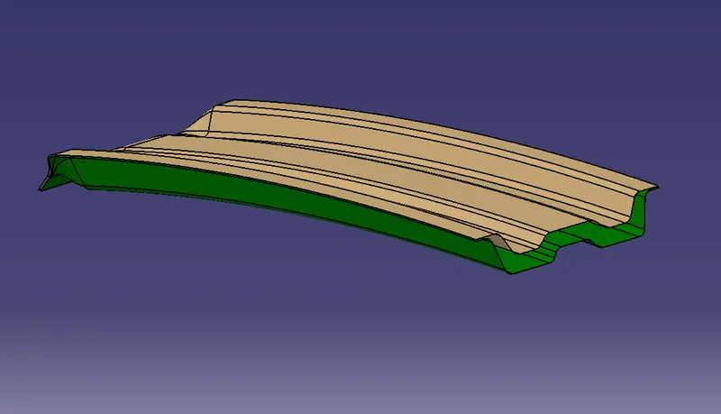
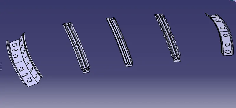
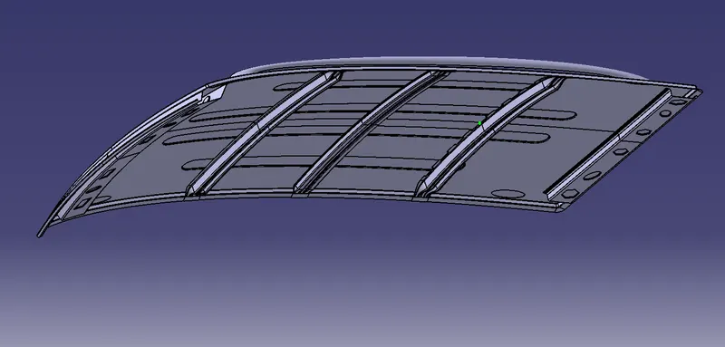
Creating theCenter Reinforcement & center bow roof rail:
- The Center Reinforcement is attached at the center yet below the roof.
- To create the center reinforcement as per the diagram, we use the offset and select the parallel curve option and give an offset value of 50mm on both sides and create a cut on the offset.
- Now create the part as per the design standards and make sure that the offset is given considering the thickness of the component.

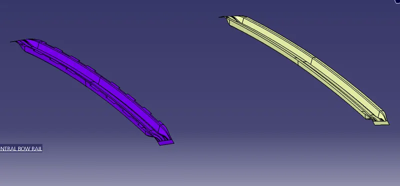
Creating the Bow roofs:
- There are 2 bow roofs that are created to give strength to the roof.
- Follow the same method as with the center reinforcement to create the bow roof.
- Now, after the bow roof is created. The mastic points need to be created.
- Use the parallel curve and connect the outer edge and parallel curve to cut the elements.
- Once created use the split option to create the mastic points.
Creating a Solid:
- After Creating the surfaces, use the thicken option to create the solids with the proper thickness.
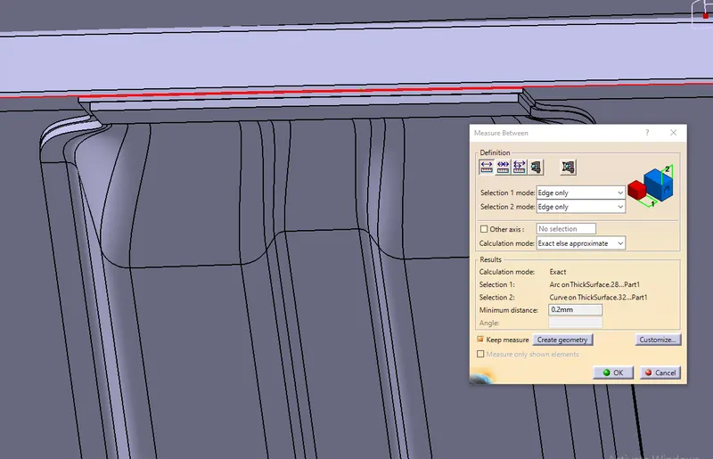
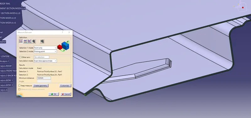
- The thickness for the Roof and front roof rail is 0.75mm, for the rear roof rail is 1.25mm, for the center reinforcement thickness is 1.5mm, and for the bow roof, it is 1.3mm.
Checking the Heat Distortion criteria:
- To calculate the Heat distortion criteria, we have to take note of few values and to note it down.
- To note down, first, we need to create a sketch.
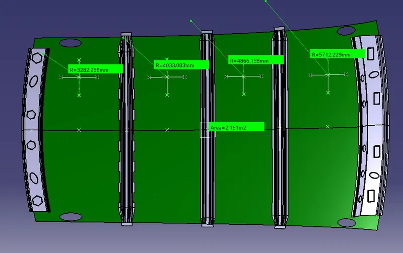
- Create a line at the center of the roof part in the 0-Y axis and then draw another line with a distance of 300mm.
- Now create the line with a distance of 100 on both sides at the line which is at
- Now create the line between the rails in the X direction and create 2 lines with a distance of 100mm on both sides.
- Now create a point coinciding with both lines.
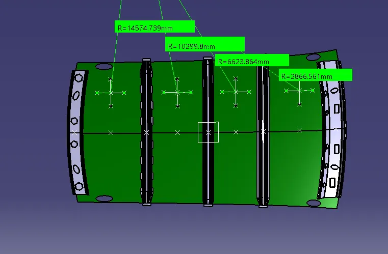
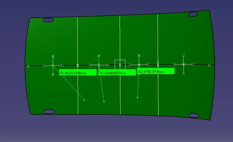
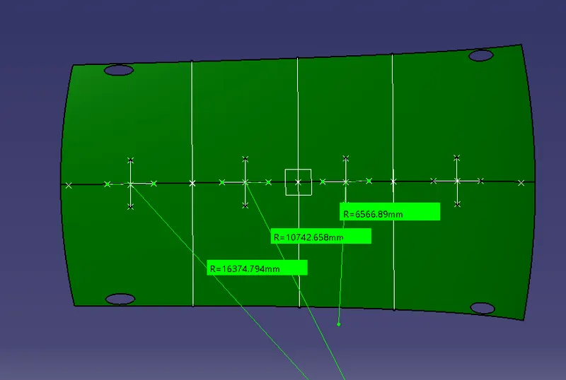
- Extract the points to the roof and create the arc using 3 points by creating two lines intersecting with each other.
- Measure the radius of the arc in the Y direction as R_y and X direction as R_x.
Checking the Snow Load Criteria:
- To calculate the Snow Load criteria, we have to take note of few values and to note it down.
- To note down, first, we need to create a sketch.
- Create a line at the center of the roof part in the 0-Y axis.
- Now create the line with a distance of 100 on both sides.
- Now create the line between the rails in the X direction and create 2 lines with a distance of 100mm on both sides.
- Now create a point coinciding with both lines.
- Extract the points to the roof and create the arc using 3 points by creating two lines intersecting with each other.
- Measure the radius of the arc in the Y direction as R_y and X direction as R_x.
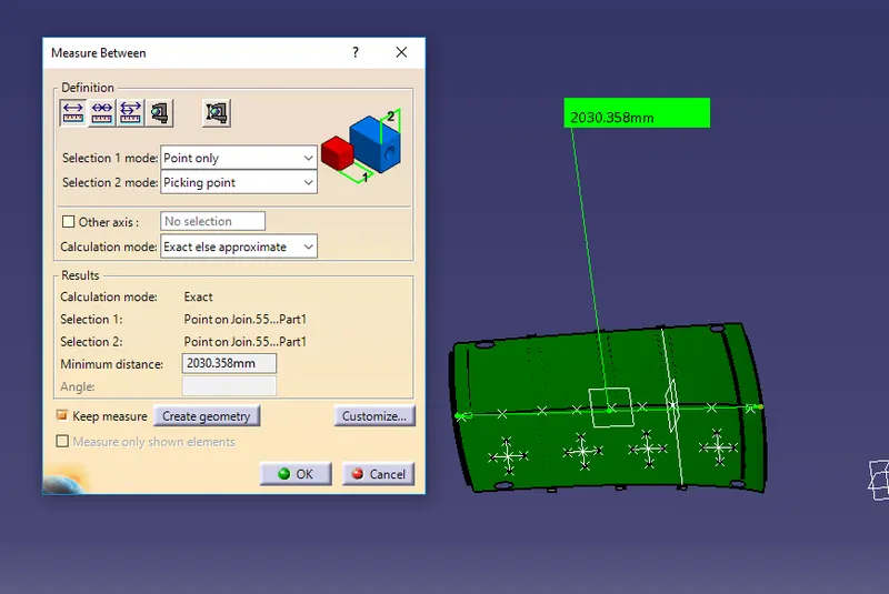
Checking the Section Modulus:
- To check the section modulus, we need to create the intersection in the Y-axis.
- After the intersection is done, fill the surface with the intersection created.
- Select the Measure Inertia option to measure the 2D inertia of the surface created.
- Note down the values.
Calculation:
Heat Distortion Criteria:
We need to find the heat distortion criteria for the following.
Center Reinforcement and second Bow roof rail:
FOR FRONT RAIL TO BOW 1:
W = [1.73 x 10^(-3) x L] + [1.85 x 10^(-8) x (R^2)/t] + [ 1.10x10^(-3) x l] - 2.68
Known values
L= 2030.358 mm
t = 0.75mm
Rx= 3282.239mm (By measuring the arc created)
Ry=14574.739mm (By measuring the arc created)
l = 531.899mm (by measuring the distance between the bow roofs)
R = 2(Rx*Ry)/(Rx+Ry) = 2(3282.239*14574.739)/(3282.239+14574.739) = 5357.88 mm
(R^2)/t = 38275837.459mm
W = 2.126
For first Bow roof to central Bow Roof:
W = [1.73 x 10^(-3) x L] + [1.85 x 10^(-8) x (R^2)/t] + [ 1.10x10^(-3) x l] - 2.68
L= 2033.705 mm
t = 0.75mm
Rx= 4033.083mm (By measuring the arc created)
Ry= 10299.81mm (By measuring the arc created)
l = 455.677mm (by measuring the distance between the bow roofs)
R = 2(Rx*Ry)/(Rx+Ry)= 2(4033.083*10299.81)/(4033.083+10299.81)=5796.004 mm
(R^2)/t = 44791545mm
W = 2.16242
For central Bow Roof Bow 2 Rail:
W = [1.73 x 10^(-3) x L] + [1.85 x 10^(-8) x (R^2)/t] + [ 1.10x10^(-3) x l] - 2.68
Known values
L= 2033.705 mm
t = 0.75mm
Rx= 4866.138mm (By measuring the arc created)
Ry= 6623.864mm (By measuring the arc created)
l = 406.547mm (by measuring the distance between the bow roofs)
R = 2(Rx*Ry)/Rx+Ry= 2(4866.138*6623.864)(4866.138+6623.864)= 5610.55mm
R^2/t= 41971082.98mm
W = 2.056
For bow 2 to rear roof rail:
W = [1.73 x 10^(-3) x L] + [1.85 x 10^(-8) x (R^2)/t] + [ 1.10x10^(-3) x l] - 2.68
Known values
L= 2033.705 mm
t = 0.75mm
Rx= 5712.231mm (By measuring the arc created)
Ry= 2866.561mm (By measuring the arc created)
l = 533.939mm (by measuring the distance between the bow roofs)
R = 2(Rx*Ry)/Rx+Ry= 2(5712.231*2866.561)(5712.231+2866.561)= 3817.42mm
R^2/t=19225268.28mm
W = 1.775
Snow Load Criteria:
For front rail to Bow 1 Roof:
Qr = [Iy x t2] / [α x s x [(Rx + Ry)/2]2 x 10-8]
Known Values:
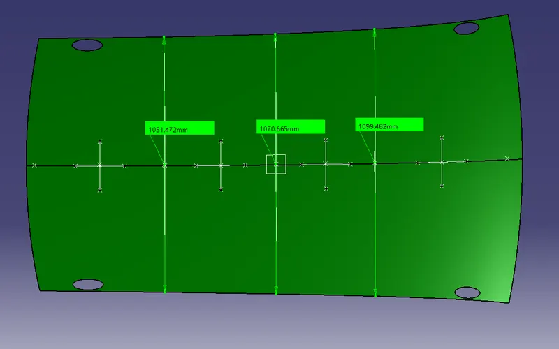
Lx= 1051.472mm
Ly= 2030.359mm
Iy= 6566 mm4
y = 16374 mm
Rx= 4020.008mm
Ry= 16374.794mm
α = My x Lx2 x 10-12 , My = Y(Ly-Y)
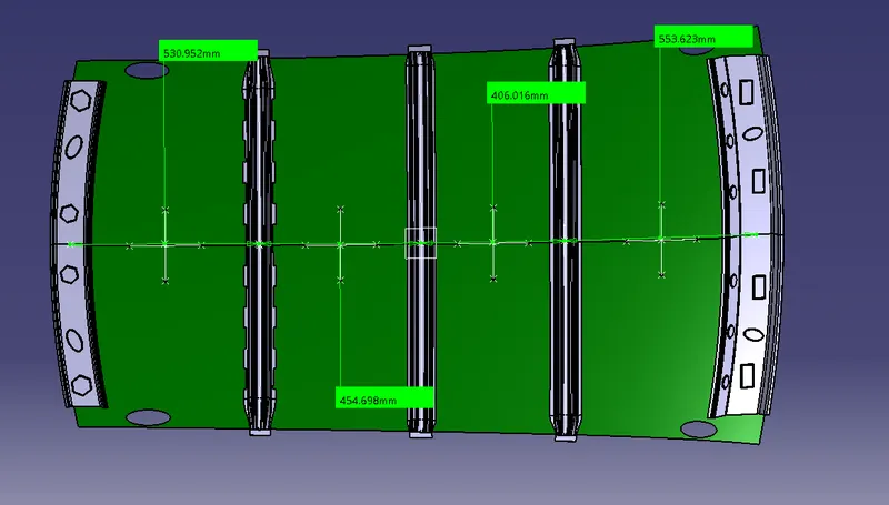
Where My= 530.952 × (2030.359 − 530.952) = 796113.14546
S=L12+L22
Where L1= 530.952 mm and L2= 454.698mm
S=L12+L22= 492.825
α = 0.8801774128
Qr= 8.188
For Bow 1 Roof to CENRTER Bow Roof:
Qr = [Iy x t2] / [α x s x [(Rx + Ry)/2]2 x 10-8]
Known Values:
Lx= 1070.6652mm
Ly= 2030.358 mm
Iy= 16440 mm4
y = 454.698mm
Rx= 4248.837mm
Ry= 10742.658mm
α = My x Lx2 x 10-12 , My = Y(Ly-Y)
Where My= Y(Ly-Y) = 716449.905378
α = 0.821260
S=L12+L22
Where L1= 454.698 mm and L2= 406.015mm
S= 430.3565
Qr = [Iy x t2] / [α x s x [(Rx + Ry)/2]2 x 10-8] = 46.59
For CNTERE Bow Roof to Bow 2 Roof:
Qr = [Iy x t2] / [α x s x [(Rx + Ry)/2]2 x 10-8]
Known Values:
Lx= 1099.482mm
Ly= 2030.358mm
Iy=718.3 mm4
y = 406.015 mm
Rx= 3792.073mm
Ry= 6566.89mm
α = My x Lx2 x 10-12 , My = Y(Ly-Y)
Where My=659508.02916
α =0.821260
Qr = [Iy x t2] / [α x s x [(Rx + Ry)/2]2 x 10-8] = 3.93
Section Modulus:
For Roof:
S = I/y
Where
I = 953800 mm4
y = Total Length /2= 2055.476= 1027.738 mm
S = I/y= 928.057 mm3
For Front Roof Rail:
S = I/y
Where
I = 6566 mm4
y = Total Length /2= 118.207/2= 59.1035 mm
S = I/y= 6566/59.1035= 111.092mm3
S = 111.092 mm3
For Rear Roof Rail:
S = I/y
Where
I = 34060 mm4
y = Total Length/ 2=87.725 mm
Where Total Length = 175.443mm (For Front Roof Rail)
S = I/y=34060/87.7215= 388.258 mm3
S = 388.258 mm3
For Bow Roof Rail 1:
S = I/y
Where
I = 16440 mm4
y = Total Length/2= = 37.9475 mm
S = I/y= 16440/37.9475= 433.230 mm3
S = 433.230 mm3
For Bow Roof Rail 2:
S = I/y
Where
I = 12560 mm4
y = Total Length/ 2= 89.876/2= 44.938 mm
S = I/y= = 279.496 mm3
S = 279.496 mm3
For Center Bow Roof Rail 3:
S = I/y
Where
I = 1390mm4
y = Total Length /2= 79.957/2= 39.97 mm
S = I/y= 1390/39.97= 34.77 mm3
S = 34.77 mm3
For Center Reinforcement:
S = I/y
Where
I = 4672 mm4
y = Total Length /2= 80.112/2= 40.05 mm
S = I/y= 4672/40.05= 116.65mm3
S = 116.65 mm3
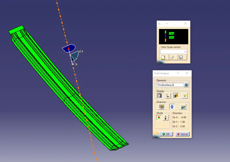
DRAFT ANALYSIS:
1.Open the Draft analysis by Insert > Analysis > Feature Draft Analysis.
2.Select the Compass - Direction in Draft Analysis and align it to the Tooling Axis and then lock it
3.After locking it a cross symbol will occur at the pointer, select the surface and the surface selected turns into green.
4.In Draft Analysis 2 box, select the green column to change the draft angle to 7 degrees.
5.The color should be green in color.
roof:
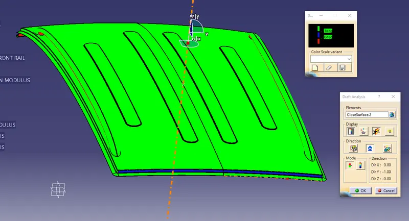
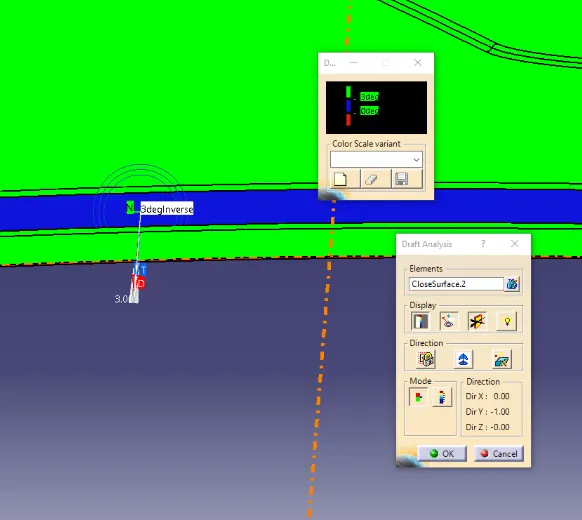
at roof flange angle is 3 degree it can show the blue colour.
FRONT RAIL:
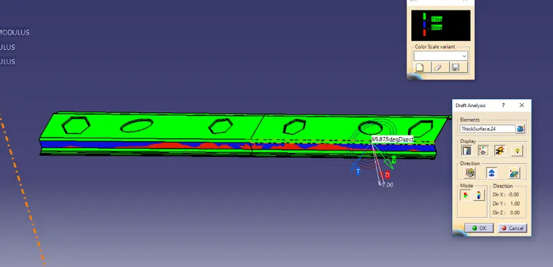
Front roof clear the draft analysis 6.9 degree angle shows in blue colour
rear rail:
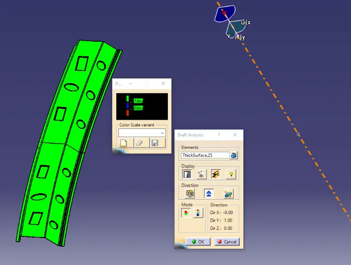
Reinforcement:
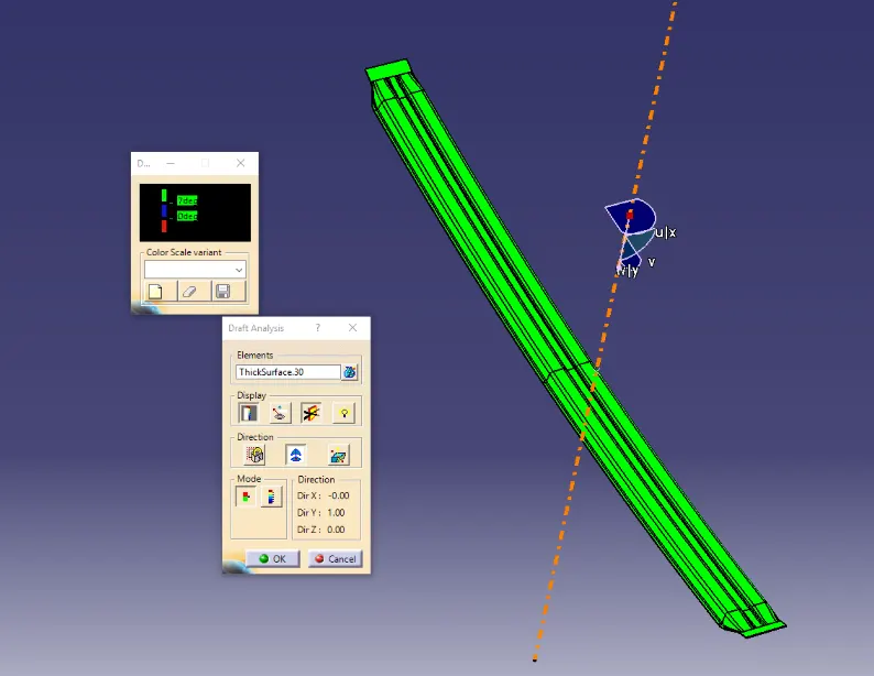
BOW RAIL 2:
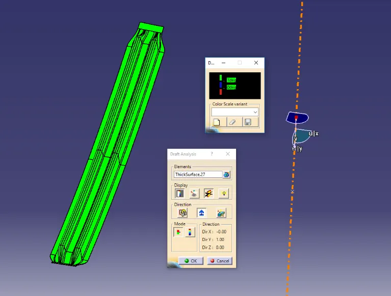
BOW RAIL 1:
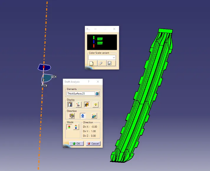
CENTER BOW RAIL:
Result:
The roof is created with the reinforcements and the heat distortion, Snow load Criteria, and Section Modulus are calculated.
Heat Distortion Criteria:
|
S.No |
BOW |
RX |
Ry |
R |
l |
L |
t |
R2t |
W |
OK/NG |
|
1 |
front rail & I Bow |
3282.239 | 14574.739 |
5357.88 |
531.899 |
2030.358 |
0.75 |
38275837.459 | 2.126 |
OK |
|
2 |
I & center Bow |
4033.083 |
10299.8 | 5796.004 |
455.677 |
2030.358 |
0.75 |
44791545 |
2.1624 |
OK |
|
3 |
center bow & bow 2 |
4866.138 |
6623.864 |
5610.55 | 406.547 |
2030.358 |
0.75 |
41971082.98 |
2.056 |
OK |
|
4 |
bow 2 & rear rail |
5712.231 |
2866.561 |
3817.42 |
533.939 |
2030.358 |
0.75 |
19225268.28 |
1.7754 |
OK |
Judging Criteria: OK <2.7mm
Snow Load Criteria:
|
S.No |
BOW |
Iy |
α |
Lx |
Ly |
y |
S |
Rx |
Ry |
t |
Qr |
Determination |
|
1 |
FRONT RAIL & BOW 1 |
6566 |
0.881 |
1051.472 |
2030.358 |
530.952 |
492.825 |
41020.008 |
16374.794 |
0.75 |
8.188 |
OK |
|
2 |
Bow & CENTRAL BOW |
16440 |
0.8212 |
1070.665 |
2030.358 |
454.698 |
430.3565 | 4248.837 |
10742.658 |
0.75 |
46.59 |
OK |
|
3 |
Center Bow & BOW 2 |
718.3 |
0.797253 |
1099.482 |
2030.358 |
406.015 |
479.819 |
3792.073 |
6566.89 |
0.75 |
3.93 |
OK |
Section Modulus:
|
S.No |
Component |
I (mm4) |
y (mm) |
Section Modulus(S) (mm3) |
|
1 |
Roof |
953800 |
1027.738 |
928.057 |
|
2 |
Front Rail |
6566 |
59.1035 |
111.092 |
|
3 |
Rear Rail |
34060 |
87.725 |
388.258 |
|
4 |
Bow Roof 1 |
16440 | 37.9475 | 433.230 |
|
5 |
Bow Roof 2 |
12560 | 44.938 | 279.496 |
|
6 |
center Bow roof |
1390 | 39.97 | 34.77 |
|
7 |
Center Reinforcement |
4672 |
40.05 |
116.65 |