Week 9 - Project 1 - Door Applique Design with Engineering Features
APPLIQUE FIXED TO THE MAIN DOOR COMPONENT
AIM: Create the Base Bracket Plastic component through the given Class-A surface.
PROCEDURE:
APPLIQUE FIXED TO THE MAIN DOOR COMPONENT.
- We have surfaced of the main door. put it in transparent mode.
- Using 3 2 1 principle to fixing these components.
-
For a fixture designer, the major portion of design time is spent deciding how to locate the workpiece in the fixture.
You know that any free body has a total of twelve degrees of freedom as below:
6 translational degrees of freedom**: +X, -X, +Y, -Y, +Z, -Z**
And 6 rotational degrees of freedom:
- Clockwise around X-axis (CROT-X)
- Anticlockwise around X-axis (ACROT-X)
- Clockwise around Y axis (CROT-Y)
- Anticlockwise around Y axis (ACROT-Y)
- Clockwise around Z-axis (CROT-Z)
- Anticlockwise around Z-axis (ACROT-Z)
You must fix all the 12 degrees of freedom except the three transitional degrees of freedom (-X, -Y, and -Z) in order to locate the workpiece in the fixture. So, 9 degrees of freedom of the workpiece need to be fixed.
But, how? By using the 3-2-1 method as shown below:
-
Rest the workpiece on three non-collinear points of the bottom surface (XY), and you will be able to fix the +Z, CROT-X, ACROT-X, CROT-Y and ACROT-Y degrees of freedom**.**
Now, rest the workpiece at two points of the side surface (XZ), and you will be able to fix the +Y and ACROT-Z degrees of freedom.
Now, rest the workpiece at one point of the adjacent surface (YZ), and you will be able to fix the +X and CROT-Z degrees of freedom.
So, you can successfully fixate 9 required degrees of freedom by using the 3-2-1 principle of fixture design.
- The jig and fixture are tools used for holding the workpiece in a correct location for mass production. Various types of fixtures are used in the industry. The 3-2-1 method is the fundamental principle for all types of fixture design.
CREATING 4 WAY AND 2 WAY LOCATORS:
- Create two 4 way locators and one 2 way locators tringle shape on the component 4-way locators creates at end positions 2-way locator create below between these two locators.
- Create portion sketch and design create two lines with intersection each other at the end.
- then give the dimensioned 15mm each line to construct the sketch.
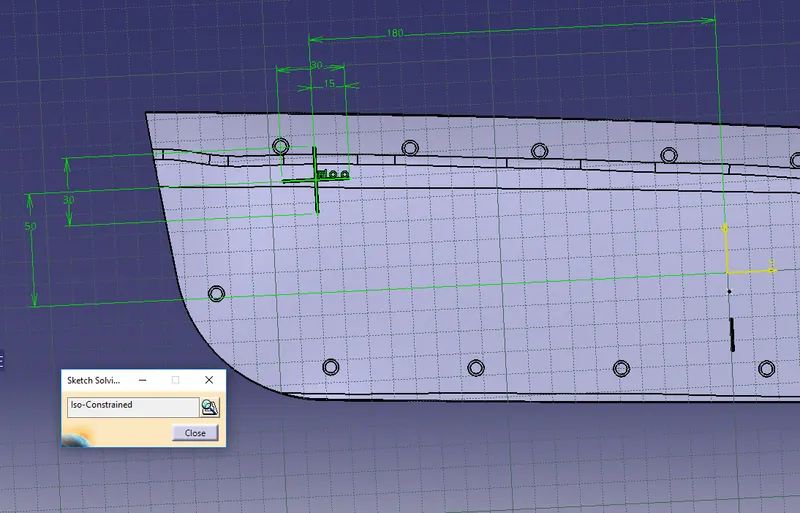
- Pad the given sketch and give the rib thickness is 1.3mm because the component thickness is 2.5 consider the design rules.
- gives the draft angle is 0.5.
- We need entry chamfer for the four rib of the locator
- all the faces make the fillet with o.3 mm
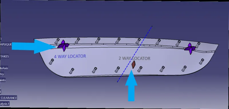
- Copy and paste the locator for moving to another location.
- IN part design using the translate option gives coordinate values to move the locator at another end.
CREATING 2 WAY LOCATOR:
- Creating 2-way locator same as the 4-way locator but it arrested only 2 directions.
- create a line with 15 mm below the surface between the 2 locators. than construct it.
- Pad the given sketch and give the rib thickness is 1.3mm because the component thickness is 2.5 consider the design rules.
- gives the draft angle is 0.5.
- We need entry chamfer for the four rib of the locator all the faces make the fillet with o.3 mm
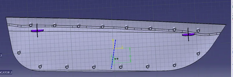
-
After creating locators check the height from the surface 1mm deviation is negligible.
-
Adjust the height of ribs to 23mm.
- Define the part body and union trim of locators click on keeping faces.
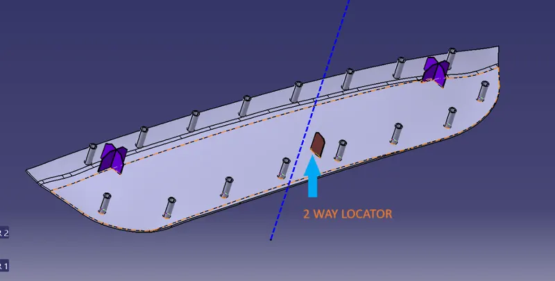
ARRESTED THE ALL DEGREES OF FREEDOM EXCEPT ROTATIONAL DEGREE OF FREEDOM FOR ARRESTED THIS CREATES A HEATSTICKS.
CREATING HEAT STAKES:
- Create boundary on applique and click on the parallel curve to move boundary 15mm inner side of the component
- creating points on the boundary.
- create one heat stake on point and then replicate it to all other points.
- using portion sketch select one point and create circles 5mm diameter as hole and heat stake diameter is 7mm. Wall thickness is 1.5.
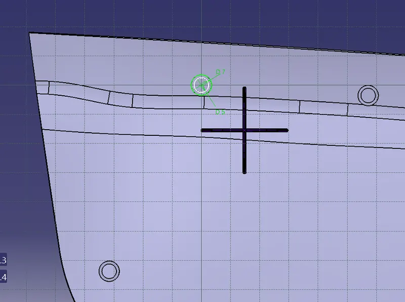
- these diameters have purely depended on the manufacturing tool.
- then insert the body name it as heat stake and pad it.
- AND copy ..paste special with a link.
- Translate point to point to all the points on the applique.
- After translation selects all her stake and assembles.
- Then define part body union trim heat sticks keep faces select.
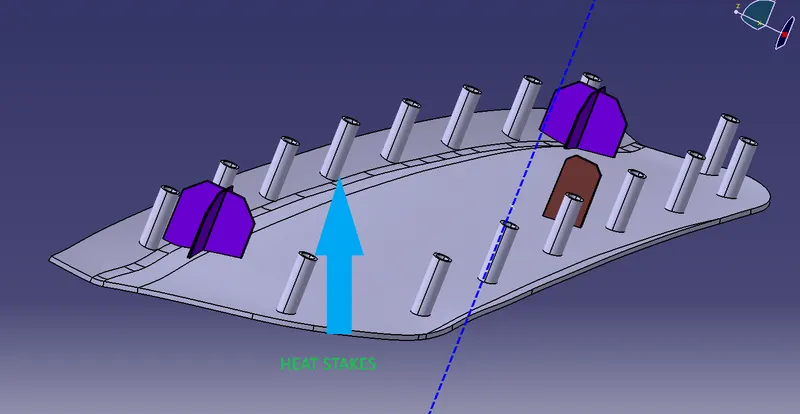
Let's start the clearance of the 4&2 way locator and heat stakes
- let's take a sketch and create a circle with using the middle point on the locator and give a radius is 15.1mm
- insert the body and pad it and define the door component and remove the clearance.
- Now we have a hole. and make holes for another two locators with 0.1 mm clearance.
- insert the geometrical set name it as clearance heats.
- create sketch pad it. and define the door component remove from it with 0.5mm clearance.
- replicate the same for all heat stakes.
DRAFT ANALYSIS:
1.Open the Draft analysis by Insert > Analysis > Feature Draft Analysis.
2.Select the Compass - Direction in Draft Analysis and align it to the Tooling Axis and then lock it
3.After locking it a cross symbol will occur at the pointer, select the surface and the surface selected turns into green.
4.In Draft Analysis 2 box, select the green column to change the draft angle to 3 degrees.
5.The color should be green in color.
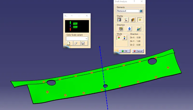
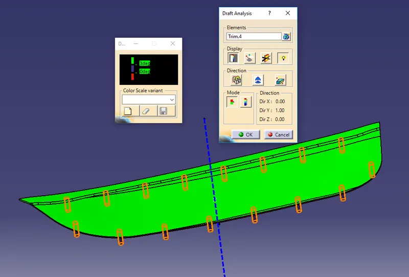
RESULT:
Created the Base Bracket Plastic component through the given Class-A surface. To begin with, the tooling axis for the given Class-A Surface should be created meeting the requirements of the draft angle and at the end perform the Draft analysis on the model.
Created the Heat Stakes and the locators considering the design rules for the door applique.
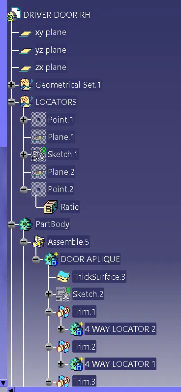
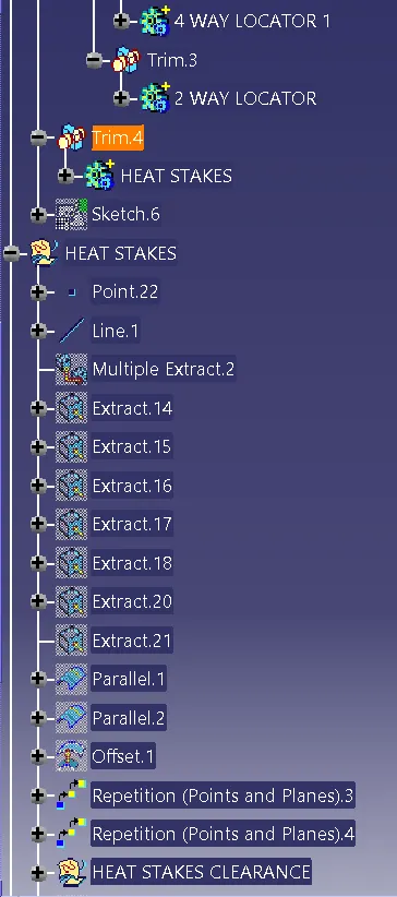
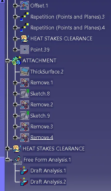
CONSTRUCTION TREE: