Week 9 Tension and Torsion test challenge
OBJECTIVE:Perform a Explicit dynamics analysis on metal bar to illustrate tension and torsion in ANSYS Workbench.
TASK
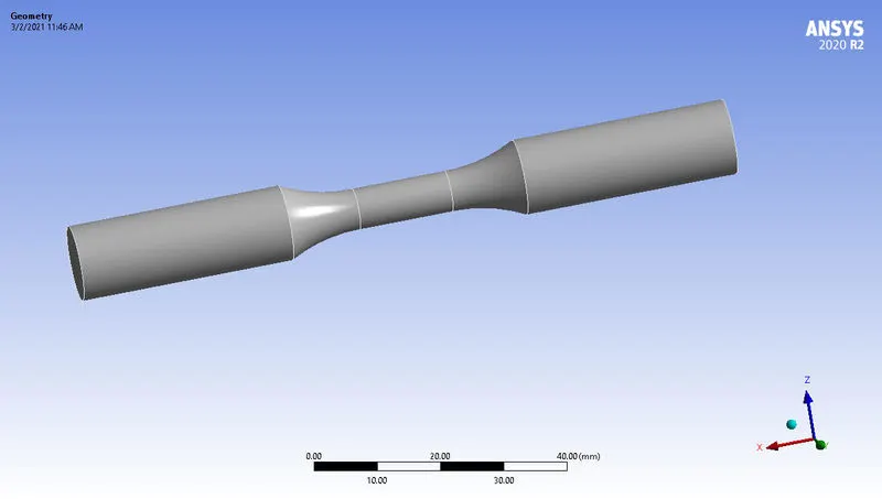
For this challenge, I would have to perform the tension and torsion test on the specimen
- For the tension test, one end of the specimen is displaced to 18mm while keeping the other fixed. I would need to find out the total deformation, equivalent stress and temperature of the specimen and attach appropriate images to show your results.
- For the torsion test, I would have to displace one end of the specimen to an angle of 1200 degree. Find out the total deformation, equivalent stress and temperature of the specimen and attach images to show your results.
CONNECTIONS
- No contacts are defined in explicit analysis.
- We just assign frictionless contact to all bodies in Body Interactions.
MATERIAL
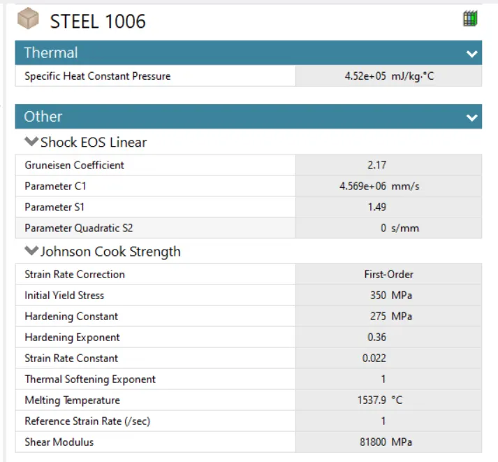
Material used is the explicit steel 1006
COORDINATE SYSTEM
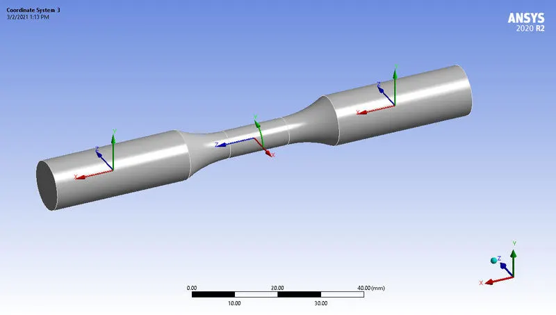
A few cordinates systems are custom made to act as position markers.
- The first is placed on the right part of the bar by selecting the face. This is made with the X-axis corresponding with the global axis.
- The second is placed on the left part of the bar by selecting the face. This is made with the X-axis corresponding with the global axis.
- The third is placed in the centre of the tube with the Z-axis corresponding with global X axis. A cylindrical cordinate is defined here
MESHING
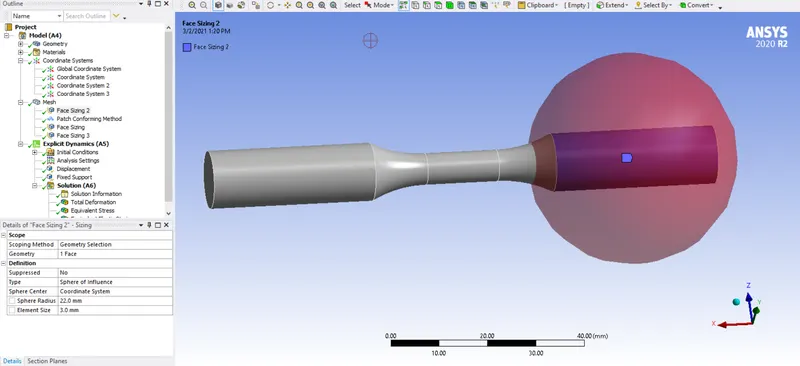
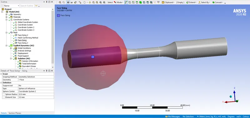
- A face sizing woth sphere of influence is defined with the coordinate systems at both ends and centre of the bar. The images below shows the meshing of the bar.
- A tetrahedron method is defined with the whole body of the bar.
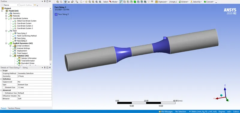
- The final sizing is specified for the middle surfaces and the various mesh sizes can be seen in the pictures below.
ANALYSIS SETTING
- End time : 0.001s
- Maximum number of cycles :100000000
- Energy error limit : 0.1
BOUNDARY CONDITIONS
TENSION
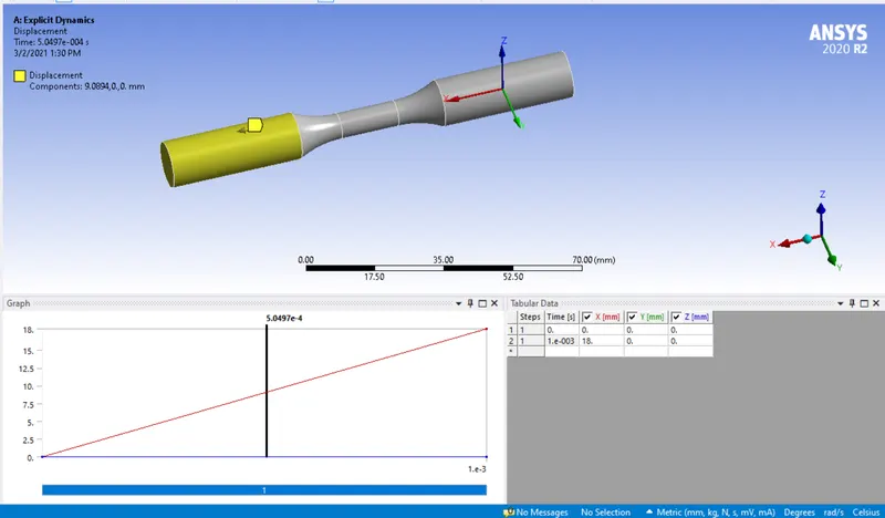
- Displacement of 18mm is assigned to the left side in the X -direction.
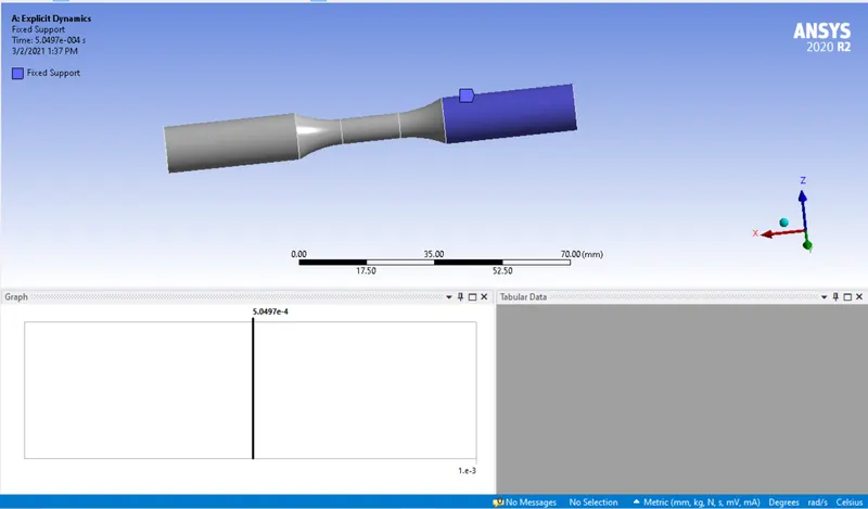
- A fixed support is defined at the right side of the bar.
TORSION
- Displacement of 1200 degrees is assigned to the left side with the last cylindrical coordinate specified previously
- A fixed support is defined at the right side of the bar.
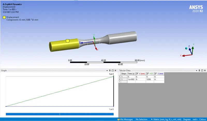
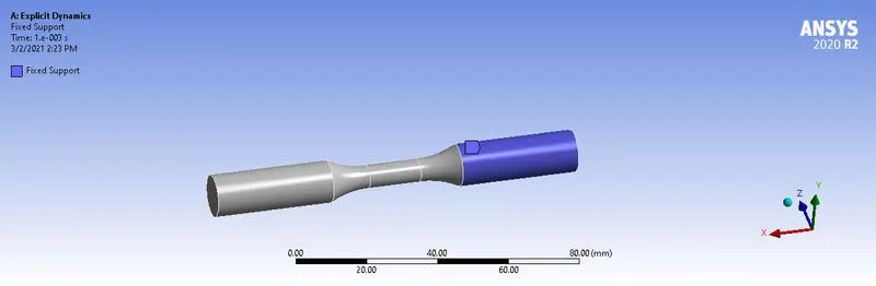
OUTPUT REQUEST
TENSION
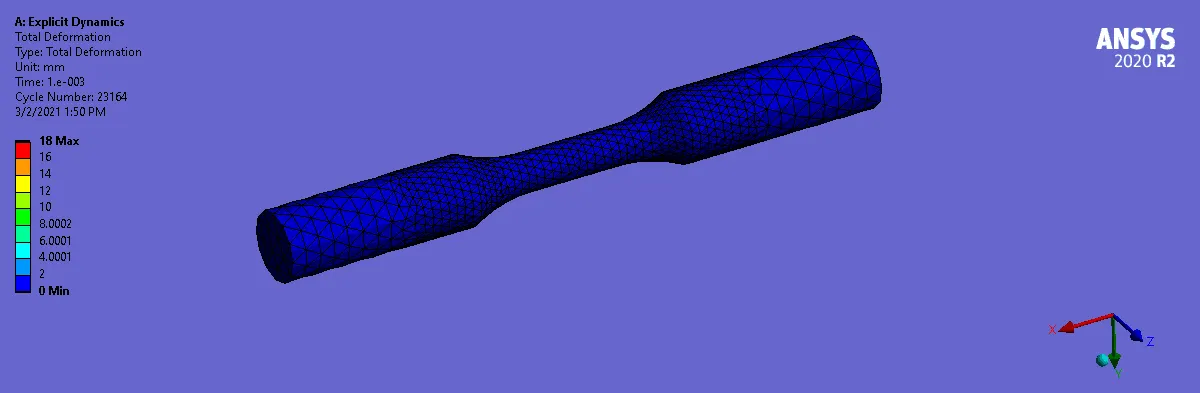
- Total Deformation (mm)
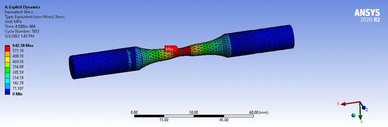
- Equivalent Stress (642.58 Mpa)
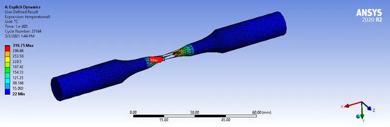
- User defined temperature (319.75 )celsius
TORSION
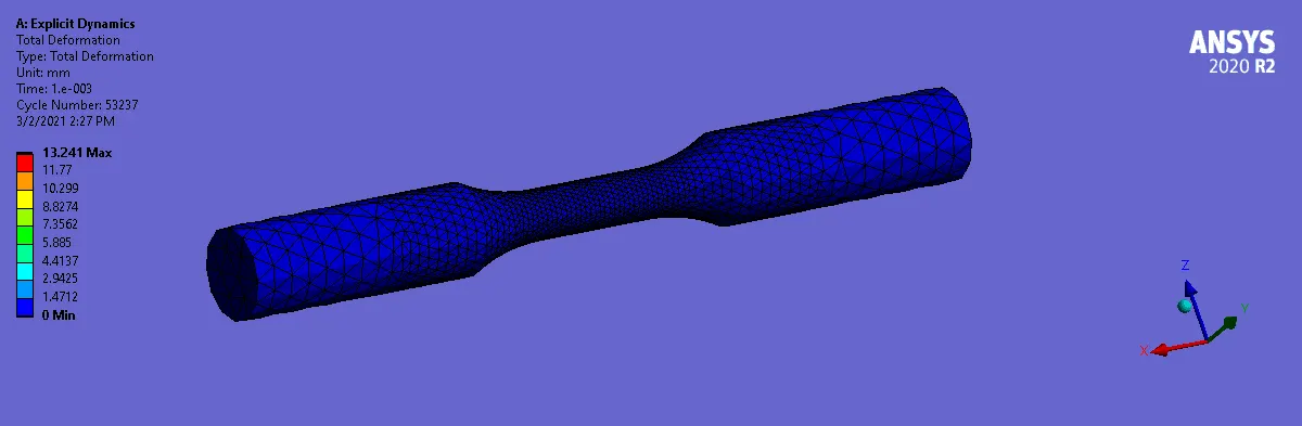
- Total Deformation (13.24 mm)
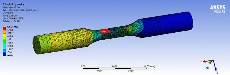
- Equivalent Stress (644.75 Mpa)
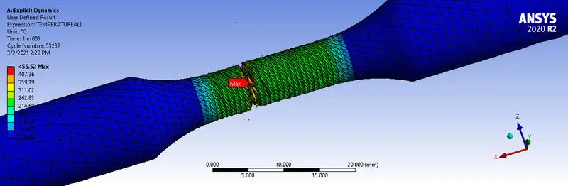
- User defined temperature (455)
DISCUSSION
| CASE | DEFORMATION(mm) | STRESS (Mpa) | TEMPERATURE(CELSIUS) |
| TENSION | 18.00 | 642.58 | 367.77 |
| TORSION | 13.24 | 644.75 | 455.00 |
The rod under tension deformed according to the specified displacement which is very much expected. Material removal and fracturing was observed in both cases as the material was strained beyound its durability limit. More stresses were developed in torsion as it requires more energy to twist a rod than to pull. The temperatures developed in bth cases was maximum in the middle portio of the rod where most of the force applied to the rod was released in a form of deformation and heat.
CONCLUSION
This task was simulated succesfully and the effect of tension and torsion was analysed and deduced.