Design & Analysis Of A Composite Pallet
ASTRACT
In this project, a composite pallet is designed to replace the common steel pallet of a cement machine in order to enhance ease of translation of the blocks on the production line. The material is chosen using general performance index and the bending of the plate is analyzed using Ansys and Matlab. Theoretical calculations are made in matlab and validated for the experimental bending simulation in Ansys. The stacking angles and layer numbers is varied to develop the best performance of the composite pallet.
PROBLEM STATEMENT
A cement block manufacturing company uses a steel pallet to enhance translation of the building blocks along a line from the cement making machine. These steel pallets are durable and strong, but they began to rust over time and their heavy weight reduces cycling time on the production line. There is a need to solve this problem to enable higher production of the cement blocks and reduce maintenance cost on the pallets.
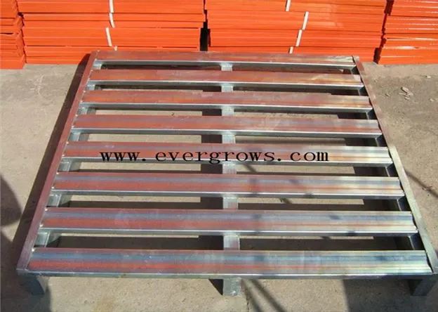
Figure 1 steel pallet for concrete manufacturing (1)
AIM
I aim to solve this problem using finite element theory. A new pallet is going to be designed with the most optimum materials used by considering elimination of rust, low weight, and high durability to reduce maintenance cost.
METHOD
First, a material which fits the above requirements should be selected. Material index equation for selecting the best performing material is used to select the best materials for this simulation.
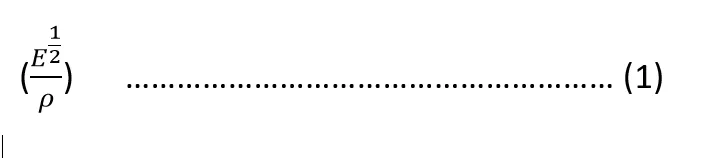
Performance index should be minimized to achieve high strength and stiffness while keeping weight minimum. The table below shows a rough estimate of performance index of materials and their cost.
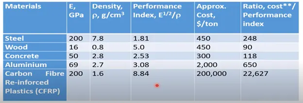
Table 1 Performance Index
From the above image, composites which has the highest performance index is selected.
ANALYSIS
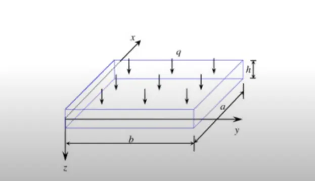
- The pallet is to be made from a laminate composite. The composite plate is designed with ACE Pre. The plate is simulated as a shell 2D element.
- Using ANSYS workbench, a laminate composite plate is designed to represent the pallet.
- The bending deformation of the pallet is simulated. The maximum deflection of the pallet should be determined.
- The design variable of layers has the following range 4 to 8. Optimization is done to increase the strength of the composite plate.
- The finite element solution is validated with analytical calculations from MATLAB.
- Advantages of the new pallet is evaluated.
METHOD
A composite laminate is two or more laminae bonded together in the direction of lamina thickness to act as an integral structural element. Laminae principal material directions are oriented to produce a structural element capable of resisting load in several directions. Each lamina can be spot by its location in the laminate, its material, and its orientation with reference axis.
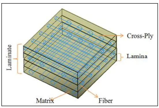
Diagram of [0/90/0/90] cross-ply laminate
Classical laminate theory (CLT) has been used to calculate deformation of composite plate. For CLT, due to simplicity over energy and vibrational principles, Newtonian approach has been used in which summing up forces and moments on the plate is often used to develop the governing differential equations. The governing equations consisting the behavior of the boundary conditions. In the present analysis,
Assumptions
- No thickness
- Neglect Transverse deformation force
- No and terms
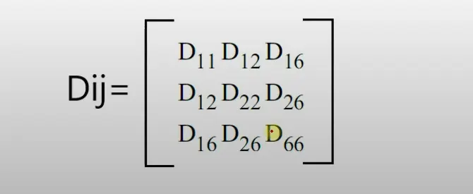
E= Elastic Modulus
V=Poisson Ratio
G=Shear Modulus
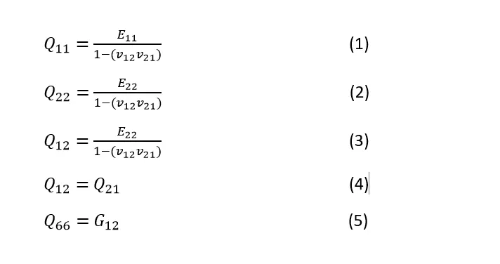
Transformed global stiffness matrix is expressed below
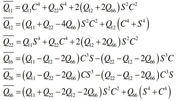
Where S =sin θ , C =cos θ
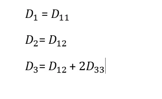
Flexural stiffness (D-Value)
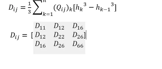

h values taken from 0 at the bottom through the thickness with the middle plate being 0
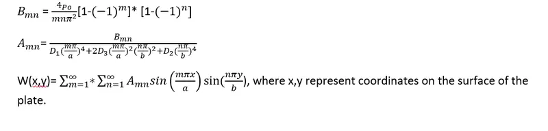
Naiver Solution for Simply Supported Composite Plates (Bending)
Finite Element Modelling
The analysis of the laminate composite plate is done with ANSYS. Using ACE Pre-Design Modeler, the pallet is designed in 2D with the following dimensions.
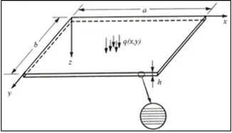
For the analysis, there are going to be two cases,
CASE_1
- Stacking Ply of [0,90,90,0]
- Lamina stacking of 4
- Thickness of 100mm
- Length of 2000mm
- Width of 1000mm
- Applied force of 18k Pa
- Ply thickness of 25mm
CASE_2
- Stacking Ply of [0,90,0,90,90,0,90,0]
- Lamina stacking of 8
- Thickness of 100mm
- Length of 2000mm
- Width of 1000mm
- Applied force of 18k Pa
- Ply thickness of 12.5mm
Material Properties
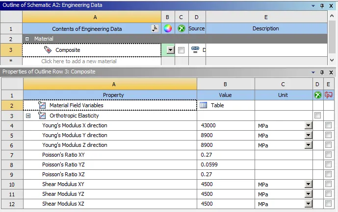
A new material data is created and all values of elastic modulus and poisson ratio is specified.
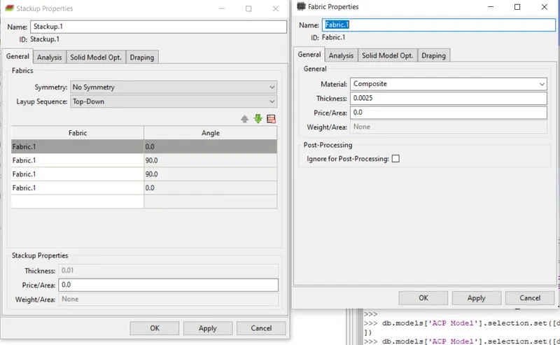
Using ACP setup, the fabric and stackups is specified as seen in the picture below
A rosette coordinate is specified to indicate the direction of the angle ply.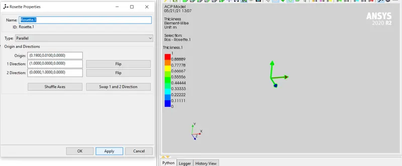
Static Structural
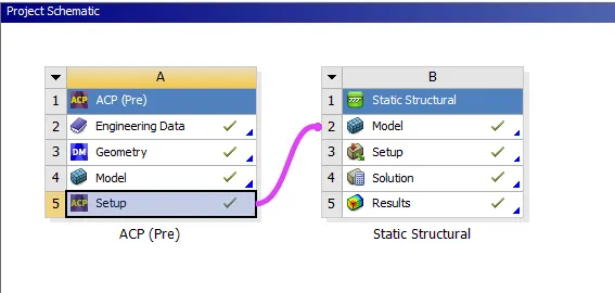
- Static structural mode is added to the ACP setup in order to initiate the bending test to analyze the composite pallet.
- A fine quad mesh of 1mm is created
- Simple supported edges are defined manually by using created node sets and defining their boundary conditions.
Nodal displacement (free, free, 0), Nodal displacement (free, free, 0) Nodal Rotation (free, fixed,free)
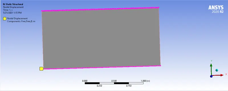
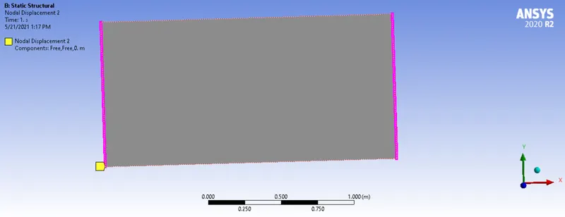
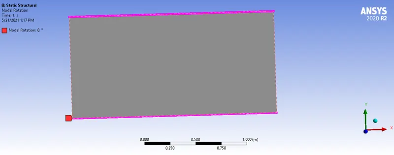
Nodal Rotation (fixed, free, free) ,Nodal displacement (fixed, fixed, free), Nodal displacement (fixed, free, fixed)
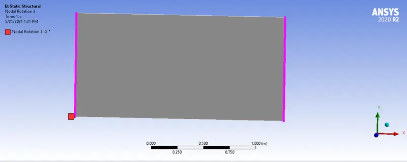
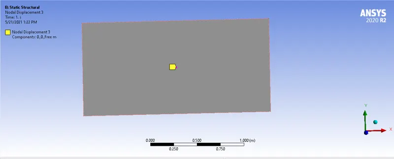
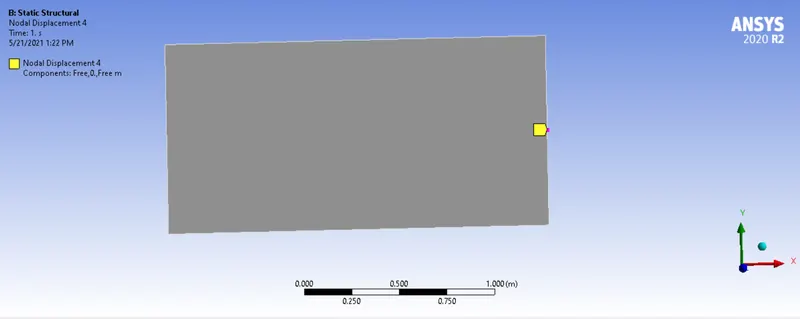
PRESSURE
The pressure to be applied should correlate with the realistic pressure which would be applied on the pallet on daily basis. The average mass of one block is 40kg. With the dimension of the pallet, 24 blocks would fit on one pallet at a time.
Total mass = 40 x 24 = 960kg
Force = 960kg x 9.8= 9408 kg/
Pressure = = 4704 Pa
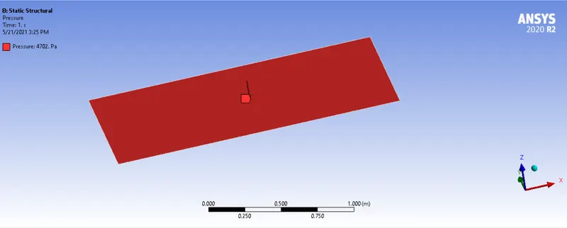
OUTPUT REQUEST
- Maximum deformation
- Equivalent Stress
RESULTS
CASE_1
- Maximum deformation (0.044mm)
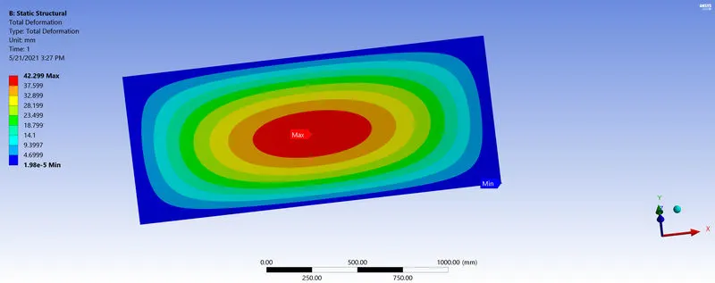
- Equivalent Stress (0.218 Mpa )
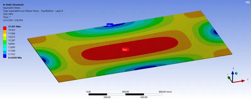
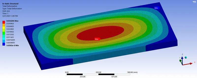
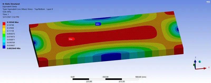
CASE_2 (8Ply)
- Maximum deformation (0.03 mm)
- Equivalent Stress (0.165 Mpa )
Validation of Results
In order to validate the results given by ANSYS, the experiment is run in Mat lab and the results are compared.
Code and results for case_1
% Material properties
E1=43*(10^9)
E2=8.9*(10^9)
v12=0.27
v21=(E2*v12)/E1
G12=4.5*10^9
%Q values calculation
Q11=E1/(1-(v12*v21))
Q12=(v21*E1)/(1-(v12*v21))
Q21=Q12;
Q22=E2/ (1-(v12*v21))
Q66=G12
% D values calculations
% 0 degrees
Q11=E1/(1-(v12*v21))
Q12=(v21*E1)/(1-(v12*v21))
Q21=Q12;
Q22=E2/ (1-(v12*v21))
Q66=G12
m=1
n=0
Qbar110=(Q11*m^4)+(2*(Q12*(2*Q66))*(m^2)*(n^2))+(Q22*n^4)
Qbar120=((Q11+Q22-(4*Q66))*(m^2)*(n^2))+(Q12*((m^4)+(n^4)))
Qbar210=Qbar120
Qbar220=(Q11*(n^4))+(2*(m^2)*(n^2)*(Q12+(2*Q66)))+(Q22*m^4)
Qbar660=(Q11+Q22-(2*Q12))*(m^2)*(n^2)+(Q66*(m^2-n^2)^2)
%90 degrees
y=0
z=1
Qbar11=(Q11*y^4)+(2*(Q12*(2*Q66))*(y^2)*(z^2))+(Q22*z^4)
Qbar12=((Q11+Q22-(4*Q66))*(y^2)*(z^2))+(Q12*((y^4)+(z^4)))
Qbar21=Qbar12
Qbar22=(Q11*(z^4))+(2*(y^2)*(z^2)*(Q12+(2*Q66)))+(Q22*y^4)
Qbar66=(Q11+Q22-(2*Q12))*(z^2)*(y^2)+(Q66*(z^2-y^2)^2)
% Dvalue
D11=(1/3*(Qbar110*((-0.025^3)-(-0.05^3))))+(1/3*(Qbar11*((0.0^3)-(-0.025^3))))+(1/3*(Qbar11*((0.025^3)-(-0.0^3))))+(1/3*(Qbar110*((0.05^3)-(0.025^3))))
D12=(1/3*(Qbar120*((-0.025^3)-(-0.05^3))))+(1/3*(Qbar12*((0.0^3)-(-0.025^3))))+(1/3*(Qbar12*((0.025^3)-(-0.0^3))))+(1/3*(Qbar120*((0.05^3)-(0.025^3))))
D21=D12
D22=(1/3*(Qbar220*((-0.025^3)-(-0.05^3))))+(1/3*(Qbar22*((0.0^3)-(-0.025^3))))+(1/3*(Qbar22*((0.025^3)-(-0.0^3))))+(1/3*(Qbar220*((0.05^3)-(0.025^3))))
D66=(1/3*(Qbar660*((-0.025^3)-(-0.05^3)))+(1/3*(Qbar66*((0.0^3)-(-0.025^3))))+(1/3*(Qbar66*((0.025^3)-(-0.0^3))))+(1/3*(Qbar660*((0.05^3)-(0.025^3)))))
D1=D11 %Nm
D2=D22 %Nm
D3=D12+(2*D66) %Nm
% Bending Calculation
a=2 %dimension in meters
b=1
m1=1 %these are not modes
n1=1
P = 4704 %in pascal
Wstorage =0
x=1 %for the middle point
y=0.5
for m1=1:20
for n1=1:20
Bmn=(4*P/(m1*n1*pi^2))*(1-(-1)^m1)*(1-(-1)^n1)
Amn=Bmn/((D1*(m1*pi/a)^4)+(2*D3*((m1*pi/a)^2)*(n1*pi/b)^2)+(D2*(n1*pi/b)^4))
w= Amn*sin(m1*pi*x/a)*sin(n1*pi*y/b) %deflection for displacement
wstorage=wstorage+w
n1=n+1
end
end
wxy=wstorage*1000 %in mm
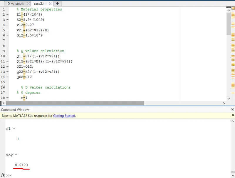
Final displacement for case_1 = 0.0423m
Code and results for case_2
% Material properties
E1=43*(10^9)
E2=8.9*(10^9)
v12=0.27
v21=(E2*v12)/E1
G12=4.5*10^9
thickness = 12.5*(10^-3) % in meters
% Q values calculation
Q11=E1/(1-(v12*v21))
Q12=(v21*E1)/(1-(v12*v21))
Q21=Q12;
Q22=E2/(1-(v12*v21))
Q66=G12
% D values calculations
% 0 degeres
m=1
n=0
Qbar110=(Q11*m^4)+(2*(Q12*(2*Q66))*(m^2)*(n^2))+(Q22*n^4)
Qbar120=((Q11+Q22-(4*Q66))*(m^2)*(n^2))+(Q12*((m^4)+(n^4)))
Qbar210=Qbar120
Qbar220=(Q11*(n^4))+(2*(m^2)*(n^2)*(Q12+(2*Q66)))+(Q22*m^4)
Qbar660=(Q11+Q22-(2*Q12))*(m^2)*(n^2)+(Q66*(m^2-n^2)^2)
% 90 degrees
y=0
z=1
Qbar11=(Q11*y^4)+(2*(Q12*(2*Q66))*(y^2)*(z^2))+(Q22*z^4)
Qbar12=((Q11+Q22(4*Q66))*(y^2)*(z^2))+(Q12*((y^4)+(z^4)))
Qbar21=Qbar12
Qbar22=(Q11*(z^4))+(2*(y^2)*(z^2)*(Q12+(2*Q66)))+(Q22*y^4)
Qbar66=(Q11+Q22-(2*Q12))*(z^2)*(y^2)+(Q66*(z^2-y^2)^2)
% D value
D11=(1/3*(Qbar110*((-0.0375^3)-(-0.05^3))))+(1/3*(Qbar11*((-0.025^3)-(-0.0375^3))))+(1/3*(Qbar110*((-0.0125^3)-(-0.025^3))))+(1/3*(Qbar11*((0.0^3)-(0.0125^3))))+(1/3*(Qbar11*((0.0125^3)-(0^3))))+(1/3*(Qbar110*((0.025^3)-(0.0125^3))))+(1/3*(Qbar11*((0.0375^3)-(0.025^3))))+(1/3*(Qbar110*((0.05^3)-(0.037^3))))
D12=(1/3*(Qbar120*((-0.0375^3)-(-0.05^3))))+(1/3*(Qbar12*((-0.025^3)-(-0.0375^3))))+(1/3*(Qbar120*((-0.0125^3)-(-0.025^3))))+(1/3*(Qbar12*((0.0^3)-(0.0125^3))))+(1/3*(Qbar12*((0.0125^3)-(0^3))))+(1/3*(Qbar120*((0.025^3)-(0.0125^3))))+(1/3*(Qbar12*((0.0375^3)-(0.025^3))))+(1/3*(Qbar120*((0.05^3)-(0.037^3))))
D21=D12
D22=(1/3*(Qbar220*((-0.0375^3)-(-0.05^3))))+(1/3*(Qbar22*((-0.025^3)-(-0.0375^3))))+(1/3*(Qbar220*((-0.0125^3)-(-0.025^3))))+(1/3*(Qbar22*((0.0^3)-(0.0125^3))))+(1/3*(Qbar22*((0.0125^3)-(0^3))))+(1/3*(Qbar220*((0.025^3)-(0.0125^3))))+(1/3*(Qbar22*((0.0375^3)-(0.025^3))))+(1/3*(Qbar220*((0.05^3)-(0.037^3))))
D1=D11 %Nm
D2=D22 %Nm
D3=D12+(2*D66) %Nm
% Bending Calculation
a=2 %dimension in meters
b=1
m1=1 %these are not modes
n1=1
P=4702 %in pascal
wstorage=0
x=1 %for the middle point
y=0.5
for m1=1:20
for n1=1:20
Bmn=(4*P/(m1*n1*pi^2))*(1-(-1)^m1)*(1-(-1)^n1)
Amn=Bmn/((D1*(m1*pi/a)^4)+(2*D3*((m1*pi/a)^2)*(n1*pi/b)^2)+(D2*(n1*pi/b)^4))
w= Amn*sin(m1*pi*x/a)*sin(n1*pi*y/b) %deflection for displacement
wstorage =wstorage+w
n1=n+1
end
end
wxy=wstorage*1000 %in mm
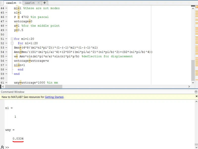
Final displacement for case_2 = 0.0323mm
DISCUSSION
Below is a summary of results collected
|
CASE |
PLY |
THICKNESS (mm) |
DEFORMATION(mm) ANSYS |
DEFORMATION(mm) MATLAB |
STRESS (Mpa) |
|
1 |
4 |
25 |
0.044 |
0.042 |
0.0165 |
|
2 |
8 |
12.5 |
0.033 |
0.032 |
0.0218 |
The deformation of the pallet decreased by some amount when the ply number was increased from 4 to eighth. The strength of the pallet increased as the ply thickness decreased with less stresses developed on the surface.
The greater the number of ply, the stronger the composite laminate. The pallet is designed with an 8 ply after this examination.
CONCLUSION
This experiment was conducted mainly to improve the steel pallet of a cement manufacturing company by creating a lighter product while retaining some optimum amount of strength. This was achieved using a composite laminate material with an 8 Ply layer and an angle configuration of [0 90 0 90 90 0 90 0]. Some advantages of this pallet is listed below
The concrete block pallet has the ability to withstand high impacts, way higher than that of a PVC or solid wood board. These impacts are inevitable in a concrete block factory; and are helpful in extending the working life of the pallet.
Since it is manufactured with fiberglass mat reinforced thermoplastics, pallets for concrete blocks are highly water-resistant surfaces. It does not need any additional coatings to be water or impact resistant.
The pallet for Concrete Blocks is an ecological alternative to other materials as the pallet can be further recycled after its use.
Due to its strength and high impact resistance, the pallets are incredibly difficult to damage and thus result in an increase in the number of cycles it can be used in a concrete block machine.
REFERENCES
https://www.alibaba.com/product-detail/Steel-Containment-Metal-Pallet-For-Concrete_60699898242.html