(ANSYS_P5) Sheet metal Bending challenge
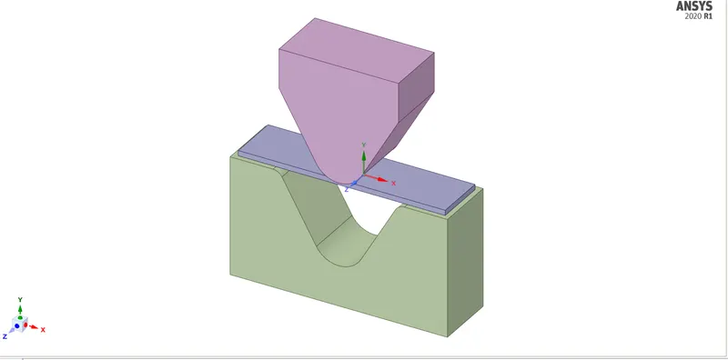
OBJECTIVE:Sheet metal bending is to be performed for 3 different materials mentioned below. Variation of certain settings is also to be performed and analysed.
TASK
Run the analysis for the material :
- Case 1:Aluminium Alloy 1199( mentioned in the course video),Copper Alloy NL and Magnesium Alloy NL. Find out the Equivalent stress, Equivalent elastic strain and Total Deformation in Y direction and compare the results for the three materials.
- Case 2:With the material as Aluminium Alloy, change the friction coefficient to 0.19 and run the analysis as mentioned in Case 1. Compare the results with that in case 1.
- Case 3: Refining the mesh on the plate such that it doesn't cross the academic limit. With Aluminium alloy as material, run the analysis as in Case 1 and compare the results.
PROCEDURE
Using Ansys workbench static structural mode is selected.
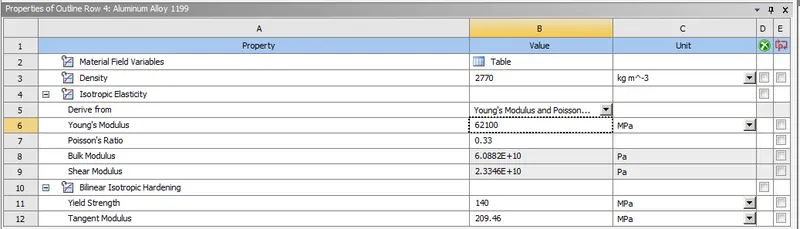
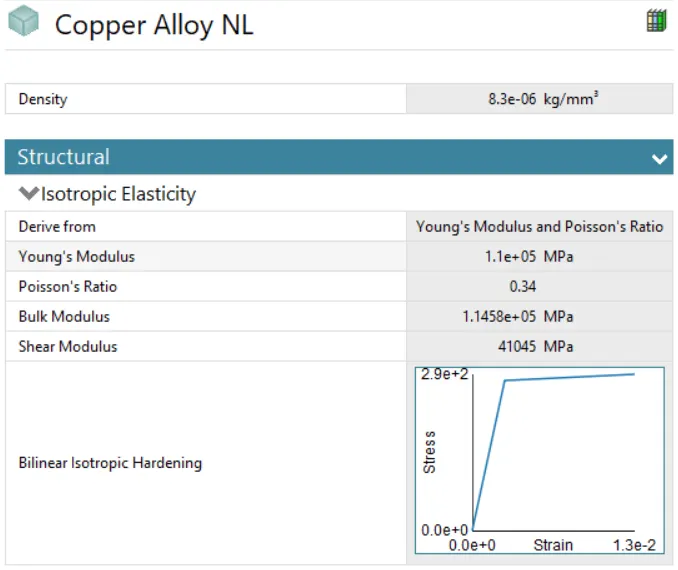
The three materials are assigned from engineering data and Aluminium NL 1199 is custom set using user defined data.
- Aluminium Non-linear 1199
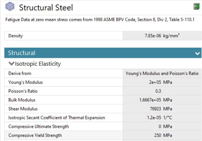
- Structural steel
Copper Alloy NL
Magnesium alloy NL
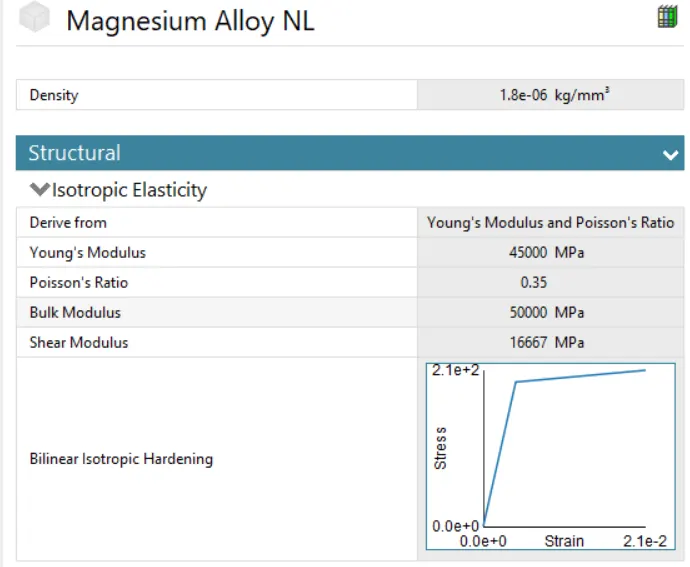
For the first case , the die and punch is assigned to structural steel and the sheet is assigned to Aluminium 1199.
CONNECTIONS
In relation to connections , the default connections are deleted as they dont represent what is in reality. A connection contact and target is assigned for the punch and sheet has can be seen below.The second connection is made between the sheet and die. The positions are seen below.
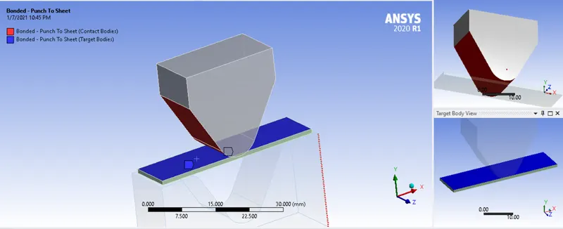
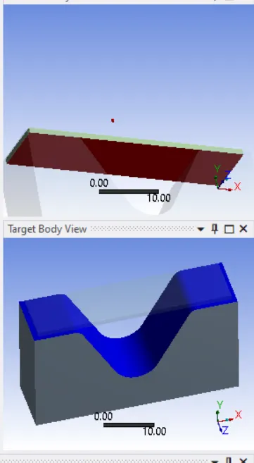
For the settings,
- For nonlinear solid body contact of faces, Pure Penalty or Augmented Lagrange formulations can be used:
-
–Both of these are penalty-based contact formulations:Here, for a finite contact force Fnormal, there is a concept of contact stiffness knormal. The higher the contact stiffness, the lower the penetration xpenetration, as shown in the figure below
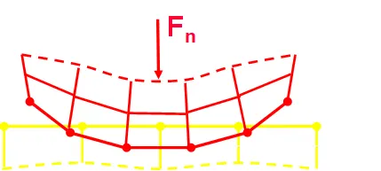
-
- Ideally, for an infinite knormal, one would get zero penetration. This is not numerically possible with penalty-based methods, but as long as xpenetration is small or negligible, the solution results will be accurate.

- The main difference between Pure Penalty and Augmented Lagrange methods is that the latter augments the contact force (pressure) calculations:

- Because of the extra term l, the augmented Lagrange method is less sensitive to the magnitude of the contact stiffness knormal
- Augumented lagrange is therefore used in this simulation because contact penetration is controlled and less sensitive to the selection of normal stiffness
- Frictional is set with a coeffiecience of 0.1
- Auto-symmetry
- Normal stiffness of 0.1 which is recommended for bending operations
- Interface of add offset and ramped effects.
MESHING
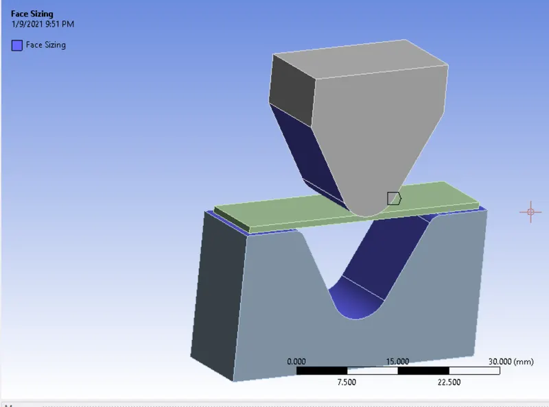
A sizing mesh for punch and die is set to 4mm
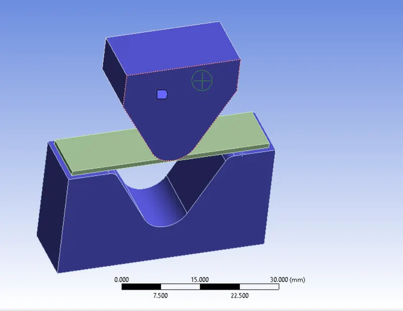
A sizing of 1mm is set for the sheet and the areas of contact which can be seen below
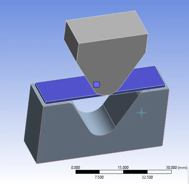
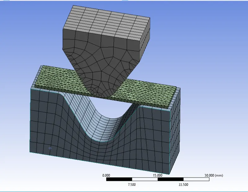
A final method is applyed to the sheet metal and the mesh is changed to tetrahedon.The final mesh is seen below.
ANALYSIS SETTINGS
A number of 10 steps is selected for this simulation and a direct solver type is used. Large deflection is turned on together with stabilization. The energy dissipation is set to 0.1
BOUNDARY CONDITIONS
Displacement of the punch is specified in the negative Y-axis and the sheet metal is fixed with displacement set to 0 in the Z axis.
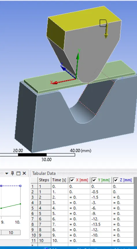
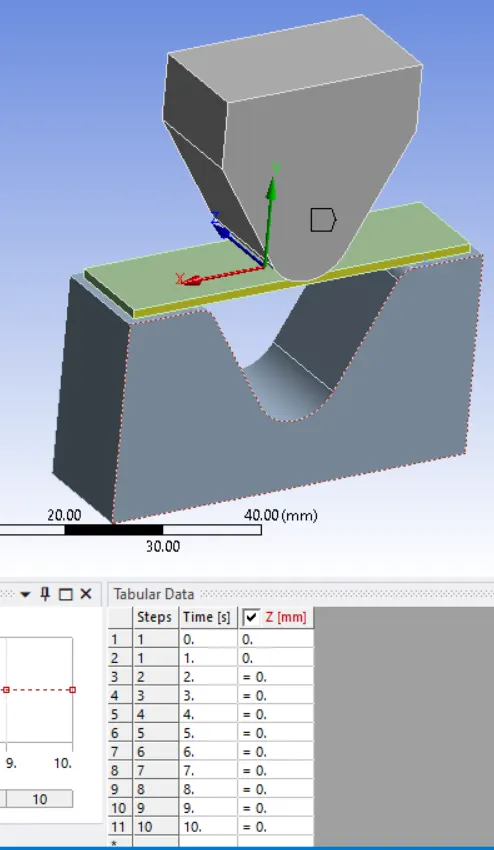
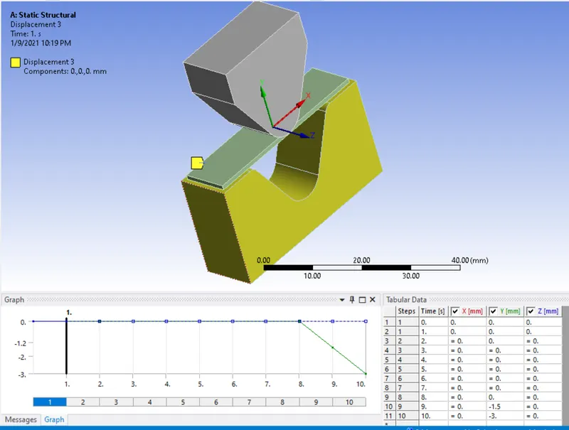
The final displacement is set by specifying the die body to be fixed at the X and Z direction but allow a -1.5 to -3 downward movement when the punch is leaving the sheet at the final times of the simulation
OUTPUT RESULTS
The output results specified for this simulation would be the equivalent stress ,strain and the displacement in the Y direction.
RESULTS AND DISCUSSION
For the first case ,Aluminium Alloy 1199,Copper Alloy NL and Magnesium Alloy NL, equivalent stress, equivalent elastic strain and Total Deformation in Y direction are compared together.
ALUMINIUM ALLOY 1199
Y-axis deformation
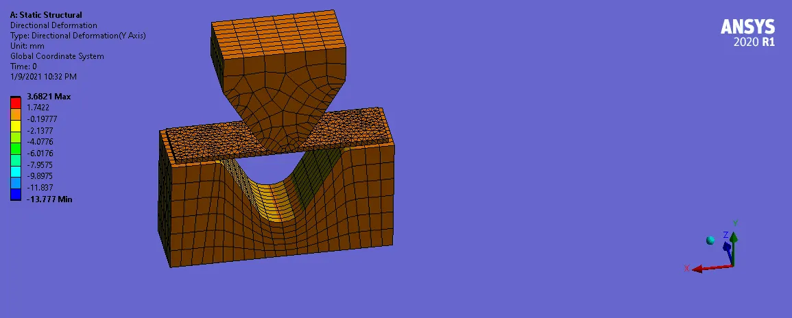
Max= 12.44mm
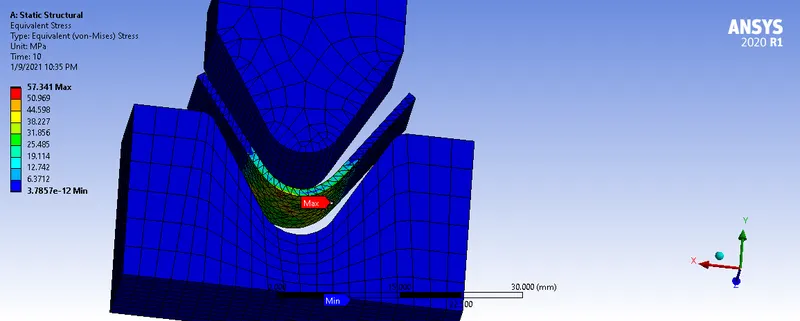
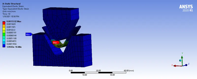
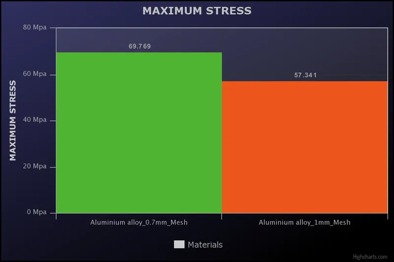
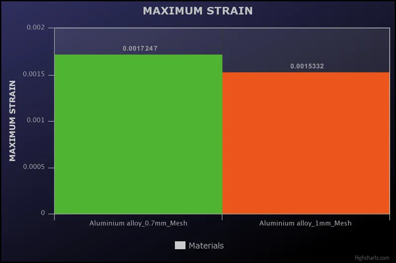
Maximum Stress and strain positions can be seen at the middle area of the sheet during deformation. Max Stress= 57.341 MPa ,Max Strain = 1.5332e-003 mm/mm
COPPER ALLOY NL
Y-axis deformation
Max = 11.66 mm
Maximum Stress and strain positions can be seen at the middle area of the sheet during deformation. Max Stress= 114.87 MPa , Max Strain = 1.7138e-003 mm/mm
MAGNESIUM ALLOY NL
Y-axis deformation
Max =11.33 mm
Maximum Stress and strain positions can be seen at the middle area of the sheet during deformation. Max Stress= 75.032 MPa , Max Strain = 2.8286e-003 mm/mm
MAXIMUM STRESS
| MATERIAL | YIELD STRENGTH | DEFORMATION Y-AXIS | MAXIMUM STRESS |
| Copper | 280 | 11.66 | 114.8 |
| Magnesium | 193 | 11.33 | 75 |
| Aluminium | 140 | 12.44 | 57 |
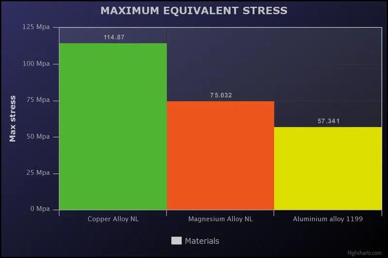
- Copper alloy developed the maximum stresses comapred to the three with aluminium the least among them. Copper which has the highest yield strength is the hardest among them as hardness is directly proportional to the yield strength. Copper also deformed the least showing its high stiffness and this leads to more stress developing on the surface as more resistance was present to the Y-axis directional deformation.Aluminium with the least strength deforms the most as less stiffness is present to resist deformation . This is evidence of very low stress developed on the surface.
MAXIMUM STRAIN
| MATERIAL | POISSON RATIO |
| Magnesium | 0.35 |
| Copper | 0.34 |
| Aluminium | 0.33 |
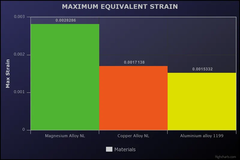
Strain is the measurement of the change in length to the original length during stress applied on the materials are analysed below.
It can be seen that magnesium had greater change in length comapred to aluminium during stress application. This can be due to the evidence of their poisson ratio has the is a direct relation to strain. Poisson ration is directly proportional to the transverse strain (tension or compression) and inversely proportional to the axial strain which is in the direction of the applied force.
Therefore the greater the poisson ratio the greater strain is expected . This is the reason for magnesium with a ratio of 0.35 having the highest strain and aluminium the least strain with ratio of 0.33
MAXIMUM DEFORMATION
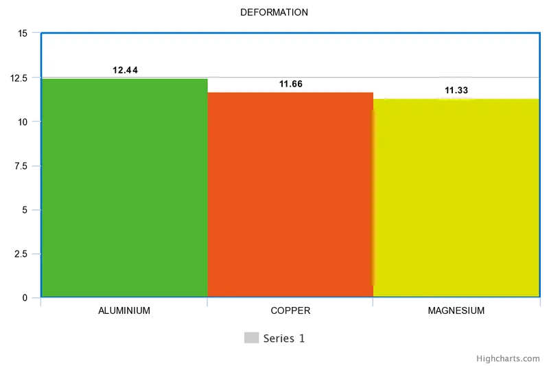
Deformation in the Y axis was maximum with aluminium. Since the maximum stress developed in all three is below their respective yield strength this deformation is elastic and therefore the total displacement relates directly to their stifness . Therefore aluminium has the least stifness of the three.
CASE_2
Case 2:With the material as Aluminium Alloy, change the friction coefficient to 0.19 and run the analysis as mentioned in Case 1. Compare the results with that in case 1.
STRESS
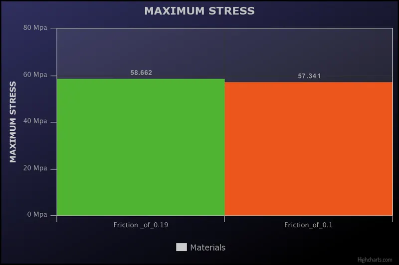
By increasing the friction on the contact surface, greater force is required to make the two surface slide or more resistance to contact movement is seen therefore more stress is produced for the same application . This is the reason for the simulation with 0,19 friction having more stress developed.
STRAIN
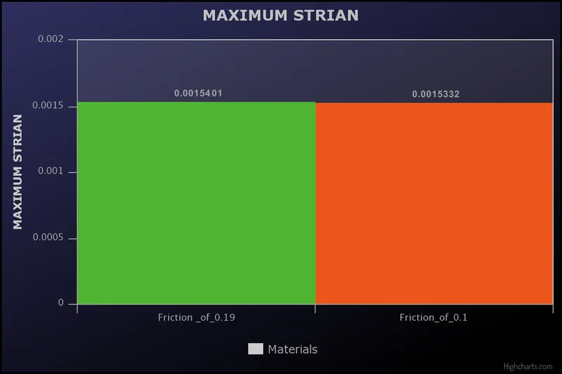
Has explained above same applies to strain effect as stress is directly proportional to strain. The greater the applied stress the greater the contraction or extension of the material.
DEFORMATION Y-AXIS
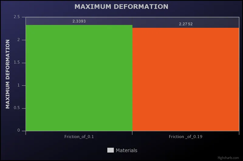
The deformation fall in direct relation to te above analysis .The greater resistance provided the material the greater the develped stresses the lesser the deformation. In this case the resistance is in a form of increased friction leading to less tendency for slipping so lesser vertical deformation is developed. This is the reason aluminium alloy 1199 with o.19 added friction deformed lesser than its counterpact with 0.1 friction.
CASE_3
Refine the mesh on the plate such that it doesn't cross the academic limit. With Aluminium alloy as material, run the analysis as in Case 1 and compare the results
The mesh size of the plate is refined to 0.7mm.
STRESS
STRAIN
Y-AXIS DEFORMATION
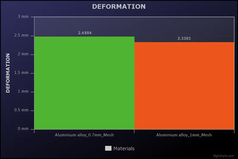
By applying grid dependency on the material aluminium, we can observe a better representation of the simulation which bring the results closer to what it is to be in real-life experiments. All parameter increased with reductio of mesh size . The solution increased in accuracy.
CONCLUSION
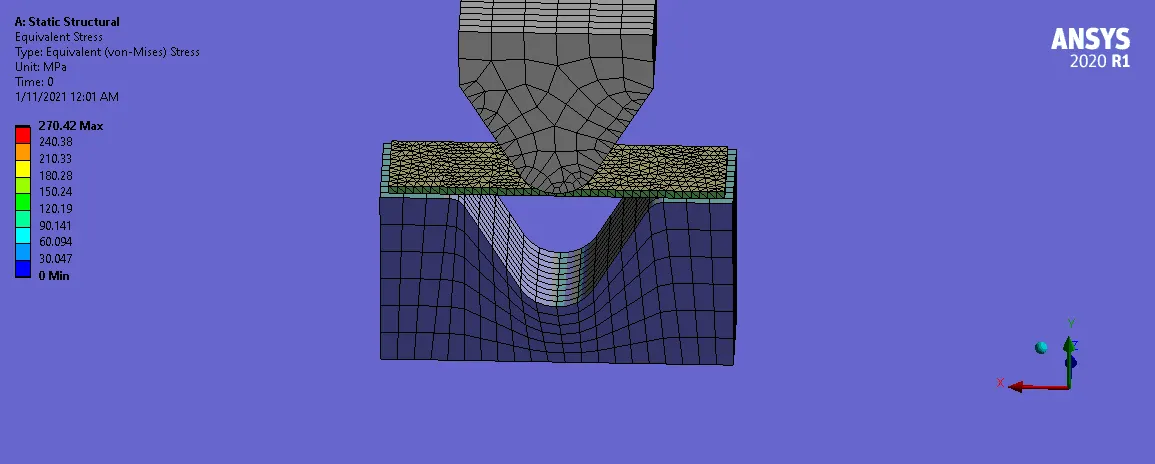
This simulation was succesful as i was able to determine the behaviour of materials with relation to stiffness, hardness, strength and strain contraction.