QUASI-STATIC ROOF CRUSH SIMULATION OF A REDUCED DODGE NEON BIW
AIM : The aim of this experiment is to determine the roof-crush resistance to an impactor by plotting the force vs displacement graph and comparing to the FMVSS 216 standard requirement.
Roof crush is the failure and displacement of an automobile roof into the passenger compartment during a rollover accident.
Every year approximately 10,000 Americans are killed in rollover accidents, accounting for about 30% of all light vehicle occupant fatalities. The number of occupant injuries is significantly higher. The relationship between injury levels and intrusion or roof crush has been statistically established, but the mechanism has been thought sometimes to be somewhat obscure. Theories advocating the idea that rollover injuries are caused by the occupants "falling" or "diving" into the vehicles interior have been advanced, but the severity of these events, and thus their potential for causing injury, has been questioned.
Observations from school bus and heavy truck rollovers also suggests that the fall and dive theories are incorrect and that another theory of the mechanism of injury in rollover accidents is required, one that relates injury to the intrusion of the roof structure into the occupant compartment or more simply to "roof crush". Today it is generally realized that the primary injury mechanism in light vehicle rollover accidents is not crushing. Rather, it is widely acknowledged that the principal injury process for contained, i.e., non-ejected, occupants involves the impact between the occupant and the vehicle interior. Since the severity of an impact depends to a large extent on the relative velocity between the impacting objects; the impact theory of injury causation in rollovers has sought to explain the increase in injuries associated with increased roof crush with an increase in the relative velocity between the occupant and the vehicle's interior which is generated by the roof crush. In the simplest terms, when the occupants hits a collapsing roof, they hit harder because the roof is moving in on them. If the roof was not collapsing, and thus moving towards the occupants, their velocity relative to the roof would be lower and the impact less severe.
Roof crush has also been identified as a cause of both full and partial ejection in rollover accidents because of ejection portals created by the collapsing roof structure. These chiefly involve broken windows but occasionally also involve the body structure. The current Federal regulation involving roof strength - 49 CFR 571.216 (FMVSS 216) - has been found to offer little benefit and is currently being reviewed. Many European manufacturers provide stronger roofs than do U.S. or Asian manufacturers despite the fact that there is no European (EEC) roof strength regulation for light vehicles.
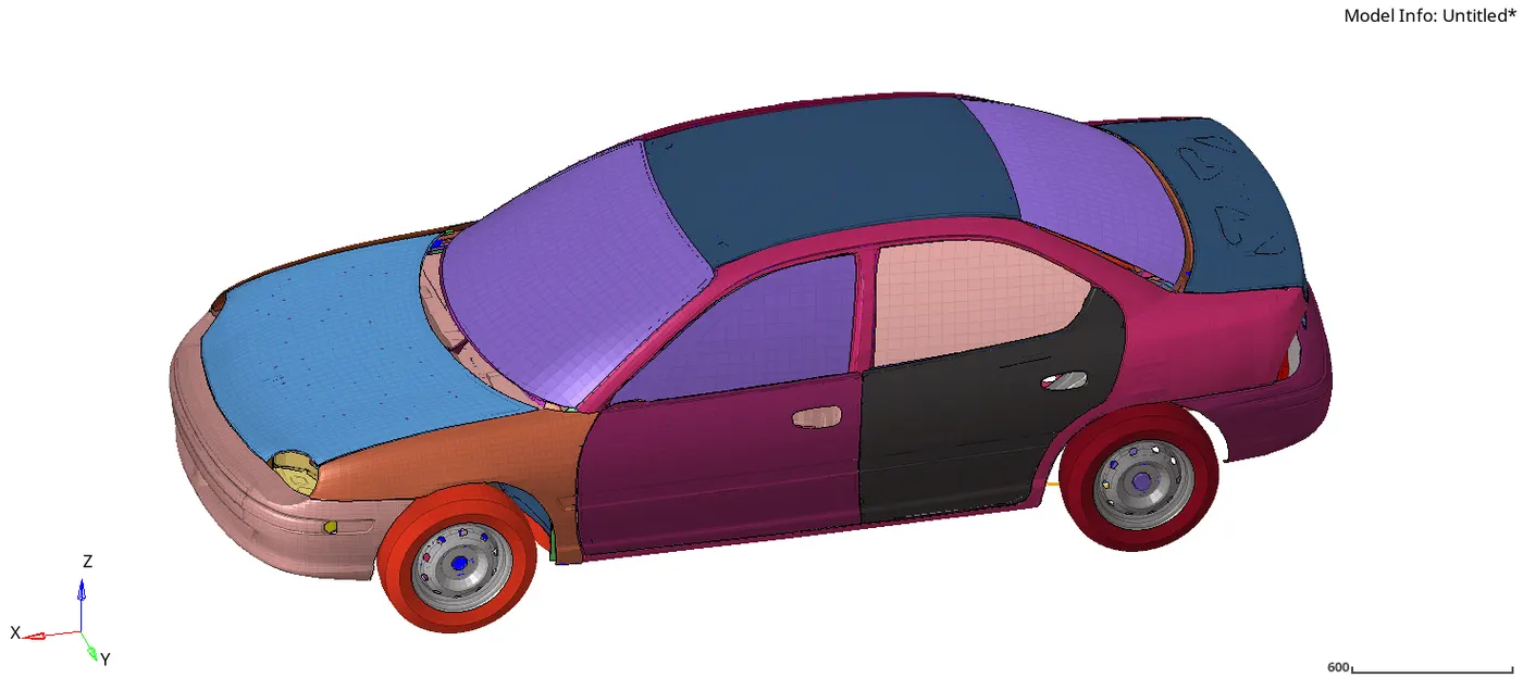
Full Car Model
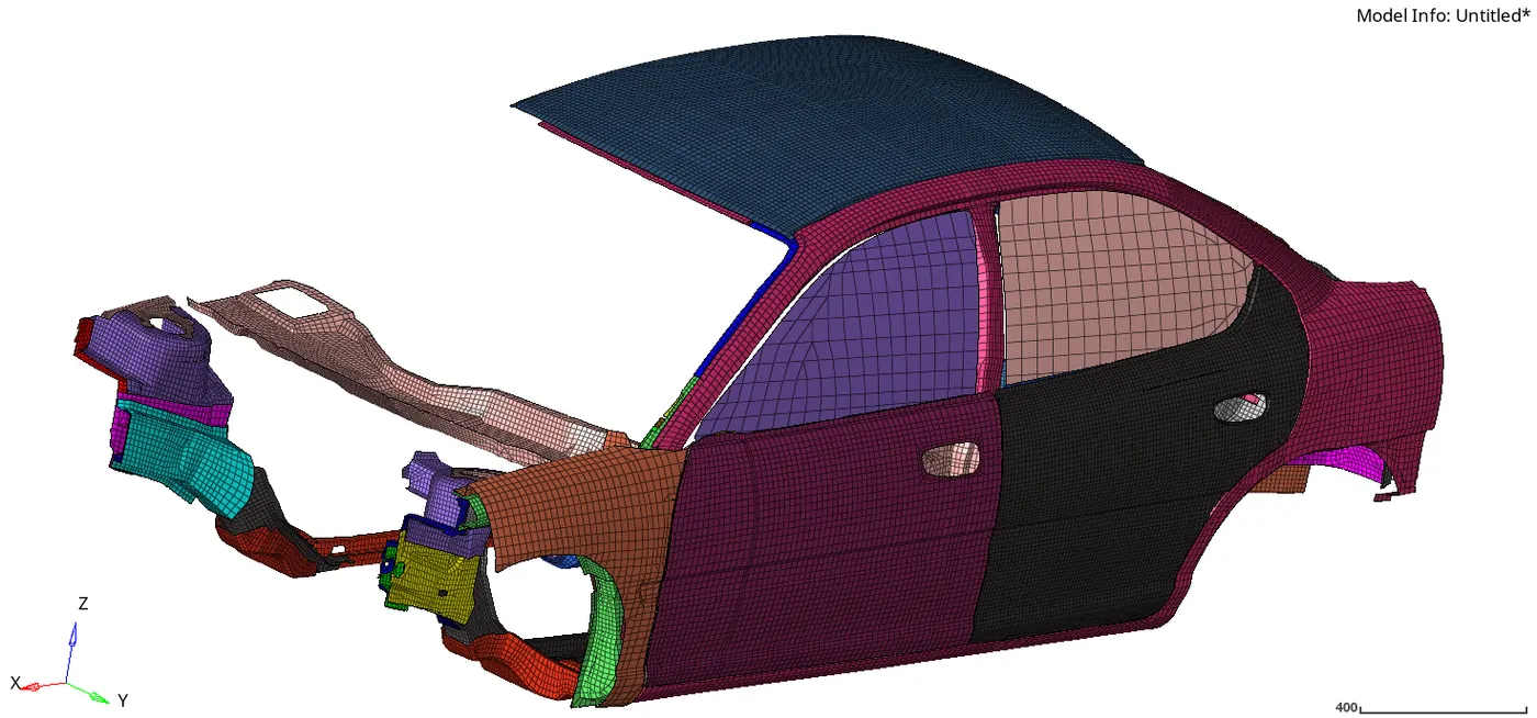
Reduced Car
UNIT SYSTEM
The unit system which was used in this model was kg ms mm
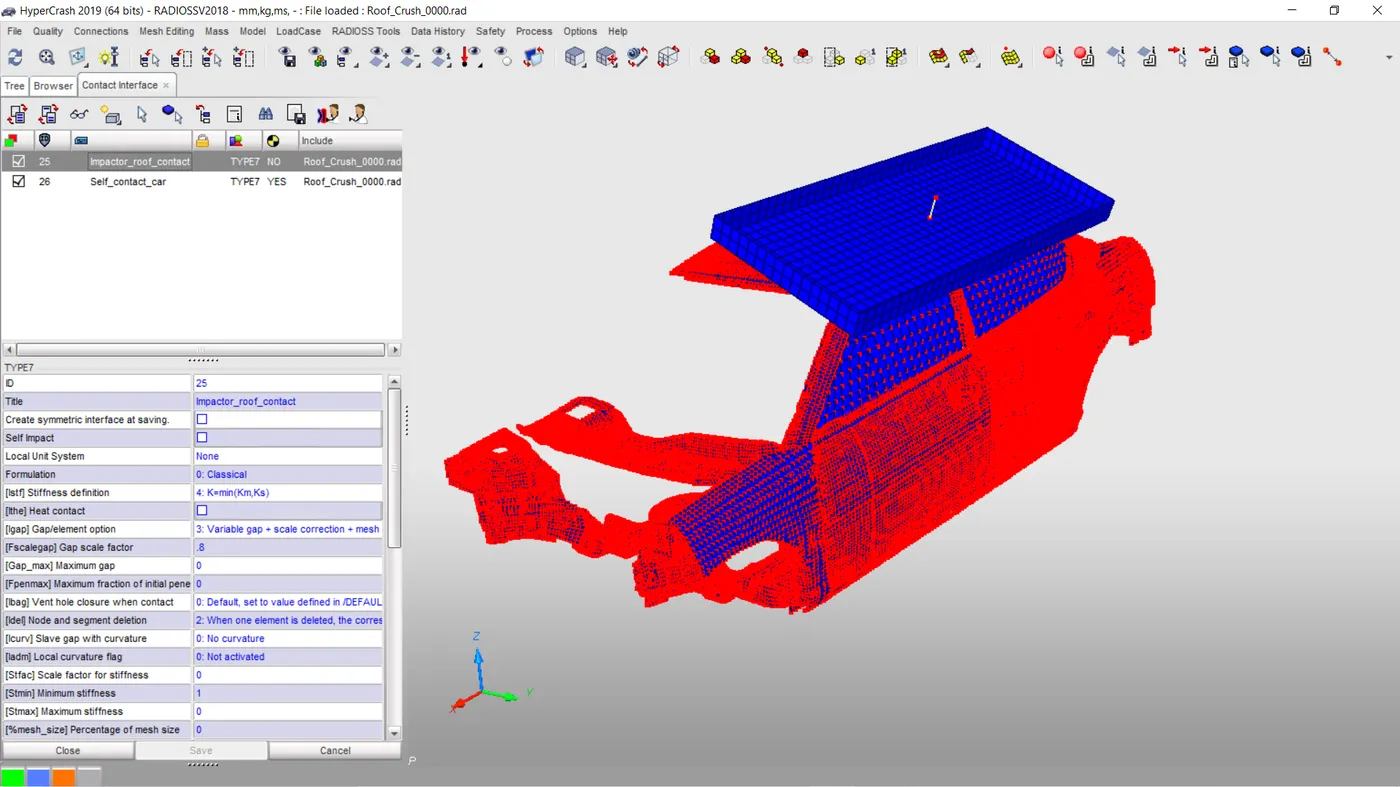
- Create an a contact interface to model how the parts interact when they come into contact with each other
- Check for element penetrations
- Check for connectivity of all parts
- Creation of rigid elements
- Positioning of impactor
- Boundary conditions
- Imposed velocity
- Creating time history output request
- Creation of animation output request
- Applying custom time step
- Model Check Quality
- Post processing results of animation (Plastic strain , displacement, Vonmises stress)
- Time step, enegy error and mass error debugging
- Plotting time history data of energy ,force v displacement graph
- Conclusion
CONTACT INTERFACE
A self contact is created for the car using the Type 7. Another type 7 is defined with the impactor as the master and the car as the slave
Parameters which control type 7 card
- Igap - determines how the size of the gap is calculated
-
Gapmin Minimum gap for impact activation - Inacti - Action to be taken if initial penetration exist
- Istif - affect how stiffness of the interface is calculated
- Iform - Friction formulation is of two types( Viscous and stiffness type) . The laer is used normally for structural analysis.
- Istif - The minimum stiffness is controled here
- Idel - If elements are attached to a deleted slave node this option specifies what is to be done to control it
Recommended properties for tpe ( 7&11)
- Igap - 2: This option sets a variable gap parameter to provide the gap between the components
-
Gapmin >0.5mm : Half of the thinnest part is mostly used - Inacti - 6 -Gap is variable with time, but initial gap is adjusted as (the node is slightly depenetrated):
gap0=Gap–P0–5%⋅(Gap–P0)">gap0=Gap–P0–5%⋅(Gap–P0). Also reduce penetrations to less than 30% of the gap
- Istif - 4 - the softest stiffnes between the slave and the master is used.
- Iform - 2- Stiffness friction Formulation. Not specified in type 11
- Istif - 1000N/mm -The minimum stiffness is controled here to avoid very low stiffness
- Idel - 2- Slave nodes are removed because of element deletion
PENETRATION AND CONNECTIVITY CHECK
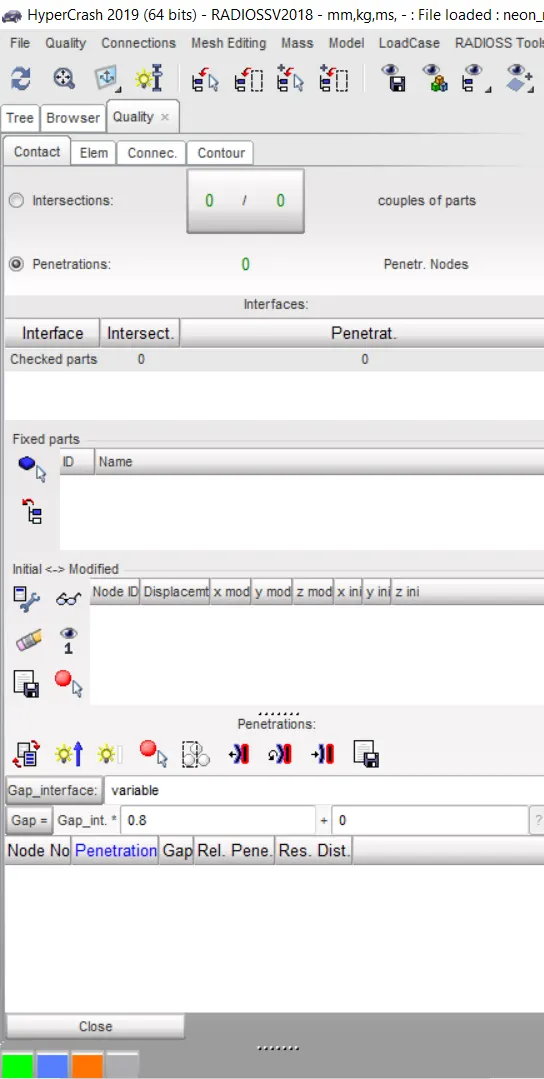
it is very important to check for element which have penetrated into the gap because this can affect the simulations results and drops to negative. The simulation becomes unstable. Below is an image of the penetration check in hypercrush. As it can be seen there where no penetration found in the model.Also checked below is the connectivity of all parts. The parts are connected together to prevent them from flying around during simulation.
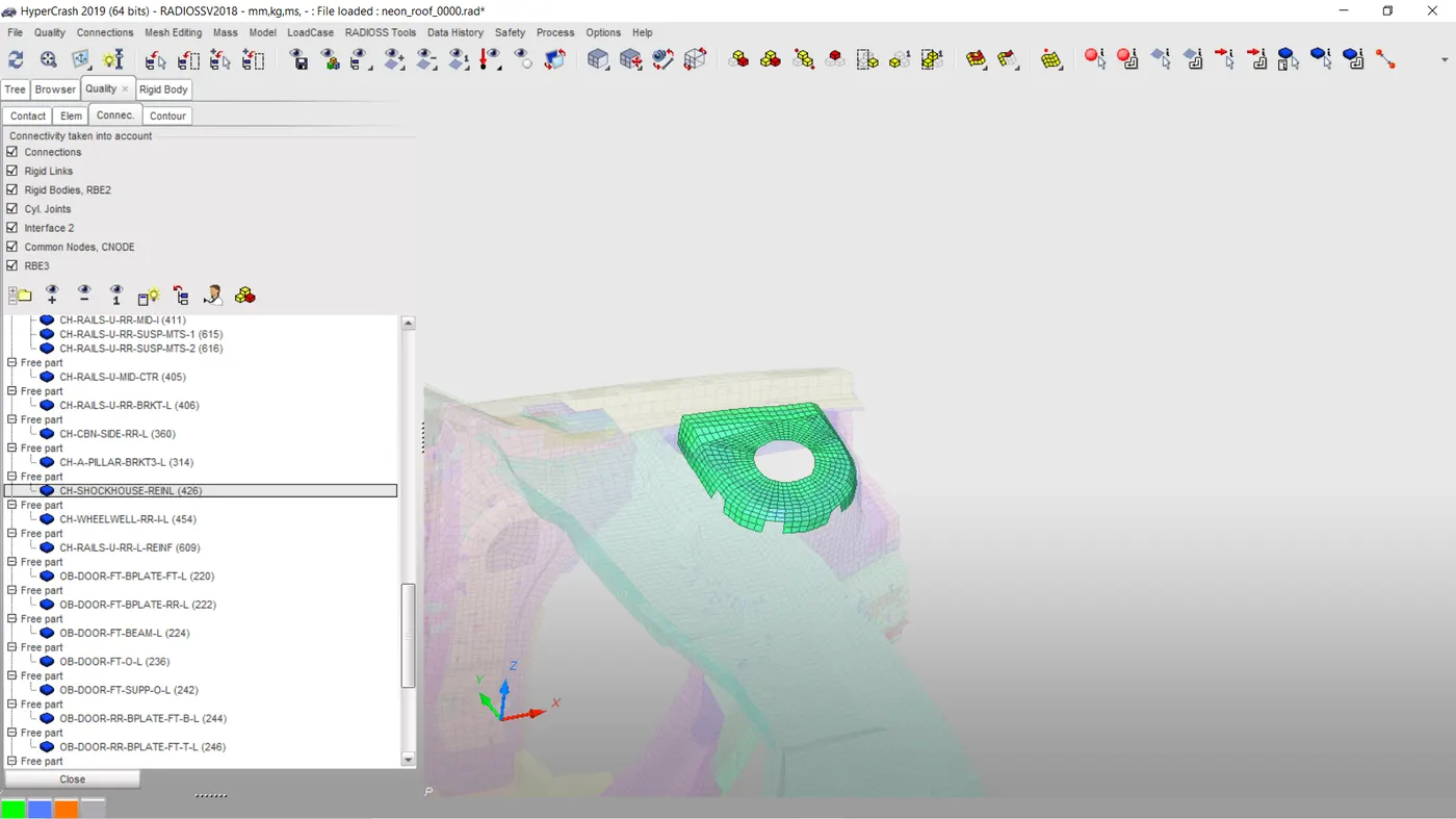
Image of free part above Image connected parts
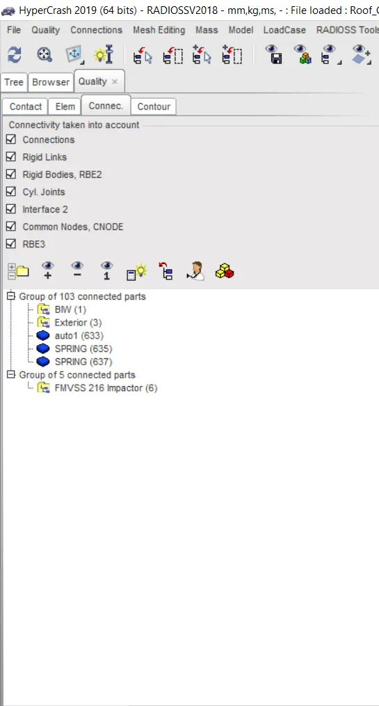
Parts where connected using iD element springs.
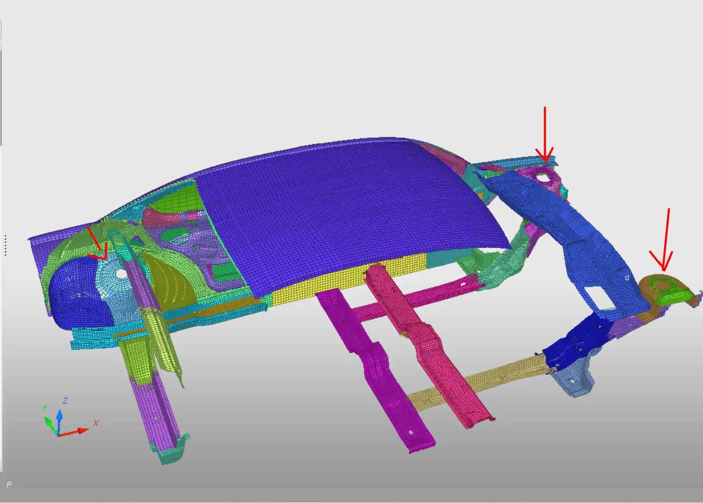
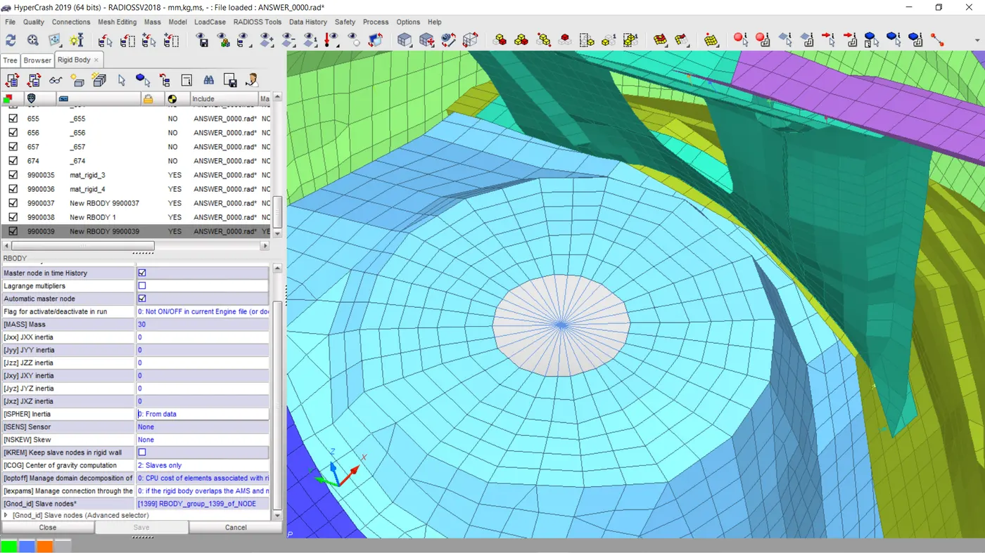
CREATION OF RIGID BODY
Rigid bodies are created at three shock tower locations to account for the tyre and shock absorbers
POSITIONING OF THE IMPACTOR
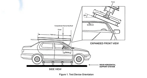
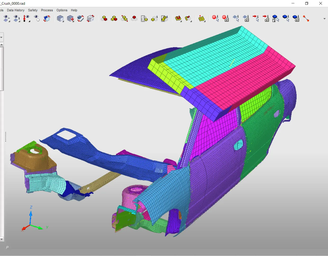
An impactor is to be place according to the FMVSS 216 standard. Using hypermesh the impactor is placed accordingly using translate and rotation tab. Below is the actual location
• This will require (in order)
• A 180° rotation about the global z-axis
• A 5° rotation about the axis through axis AB
• A 25° rotation about the axis through axis AC
• A translation to put point A at global ( -3500.00, 584.822, 1343.06)
BOUNDARY CONDITIONS
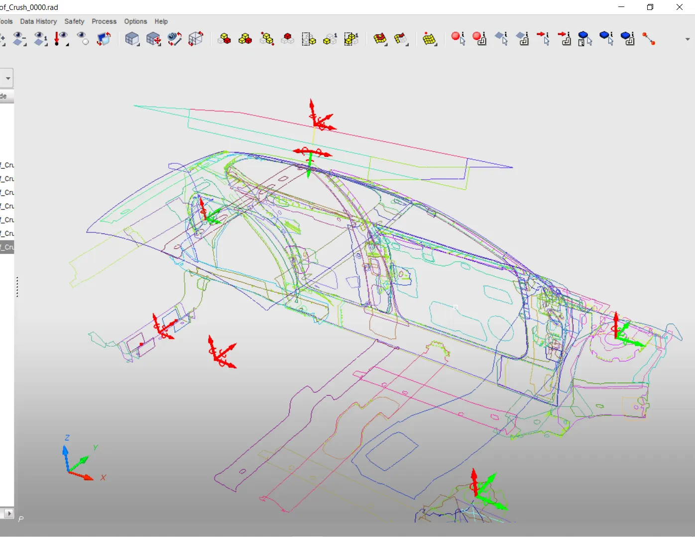
Some boundary conditions are applied at specific points to control the movements of these parts.They are as follows
- Shock Towers: The motions are opened in all translation and rotational motion except for normal z-direction.
- Rigid body at the right hand side: The motions are locked in all translation and rotational motion.This controls the motion of the right hand side of the car.
- Spring: The spring connected to the impactor by a rigid body is also locked in all directions to keep the end fixed.
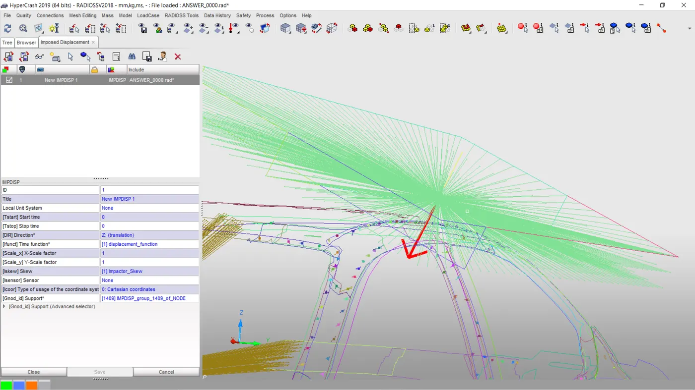
- Impactor_Skew: A skew is created for the impactor to control the axis which the displacement is going to be definrd with.The motions are locked in all translation and rotational motion except for normal z-translational direction.
IMPOSED VELOCITY
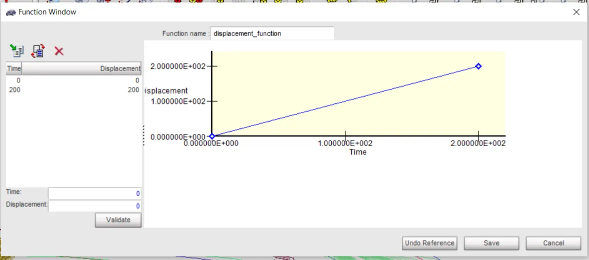
An imposed displacement is added to the impactor to control its motion. This displacement is defined using the prior created skew for only z_translational movement. A function is defined for 0mm/ms to 0mm/ms and 200mm/ms to 200mm/ms.This velocity applied t the impactor.
TIMESTEP CONTROL
Engine File
• Use a constant nodal time step of 0.0005ms with CST
• Print time history every 0.0001 seconds
• Solve for 200 ms
• Create an animation file every 0.005 seconds
CREATING TH OUTPUT REQUEST
In order to post proccese the results of the simulation , the required data must be rquested. It can be seen below the requested uotput file ad the variables selected is left at default (DEF). All the sections are requested together. Intrusions at certain locations with a reference skew
- Impactor spring
- Contact Interface
ANIMATION FILE REQUEST
Elemental Energy
• Elemental equivalent plastic strain
• Elemental hourglass energy
• Elemental von Mises stress
• Nodal added mass
• Turn on parallel arithmetic
MODEL QUALITY CHECK
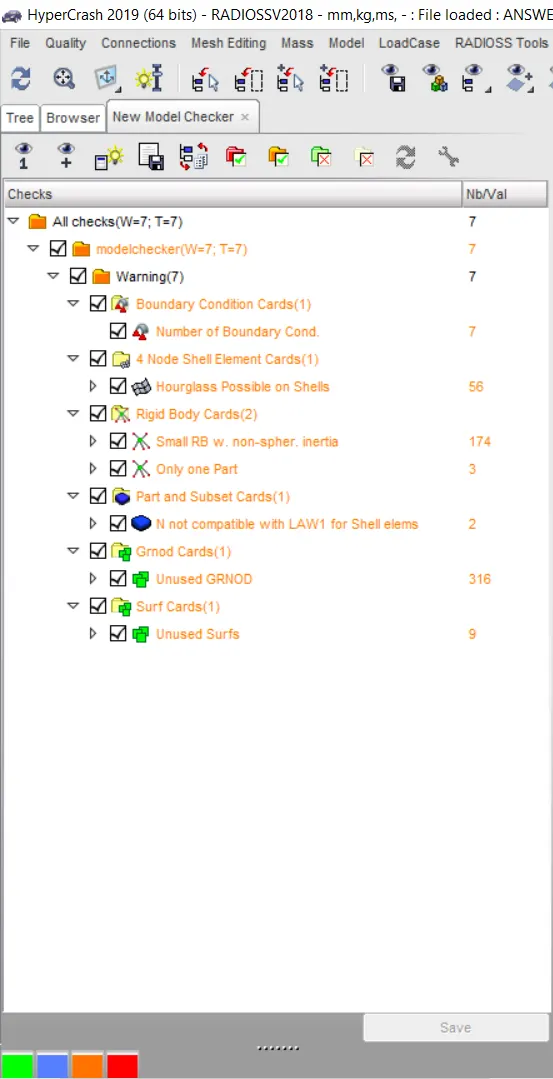
It is important to check for possible errors that may occur during simulation and model checker shows all the errors together with warnings. Below it can be seen that no errors was seen during this check.
TIMESTEP AND ENERGY ERROR DEBUGGING
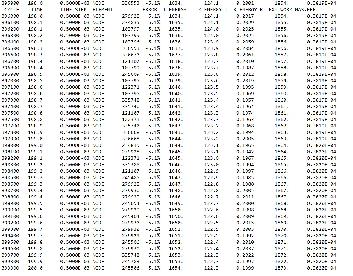
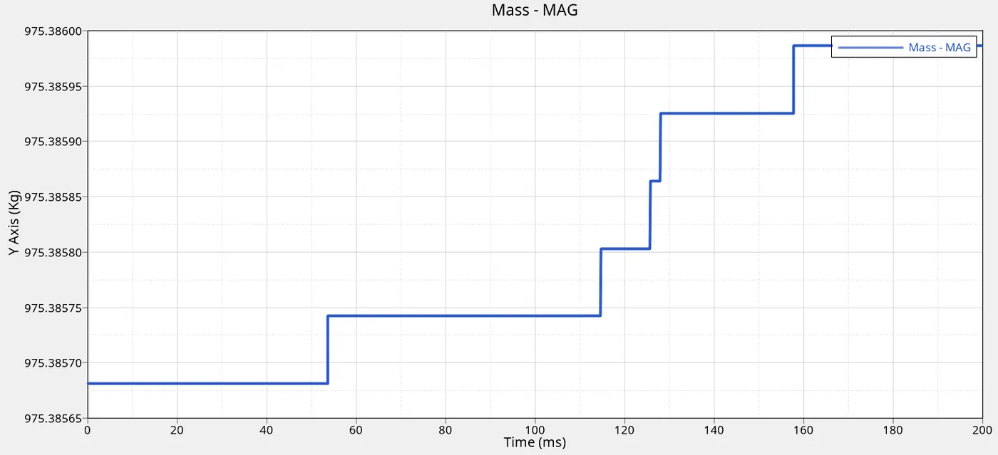
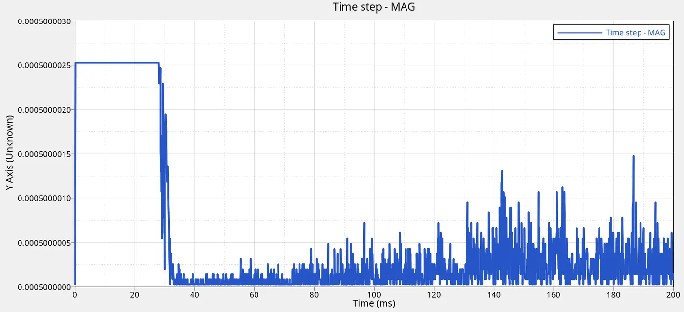
The time step through the simulation was as expected with the minimum time step not less than 0.0005ms and the energy error was well below 15%. Overall the mass change with a percentage of 0.038% .Mass change is well below 1% .
RESULTS
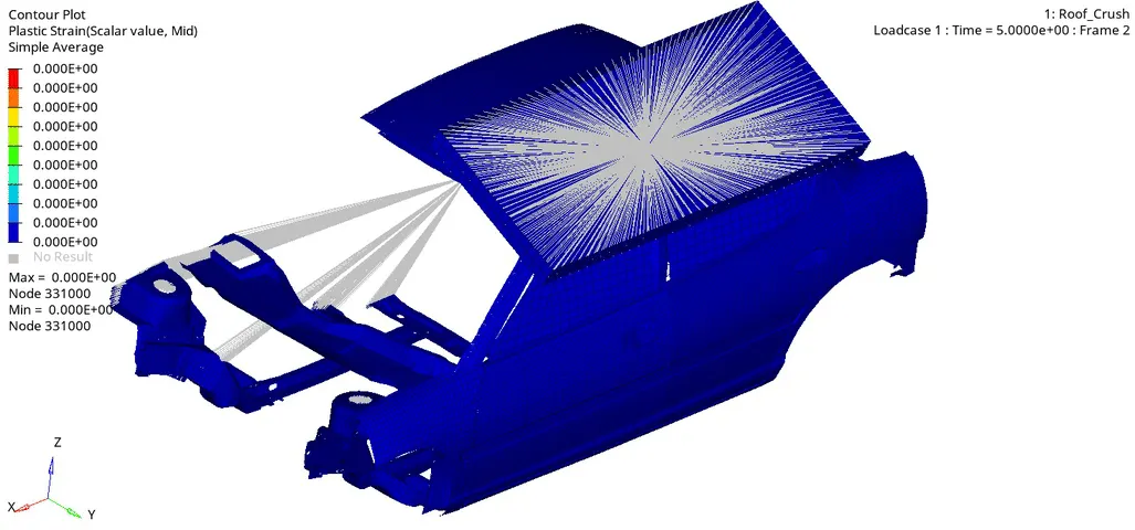
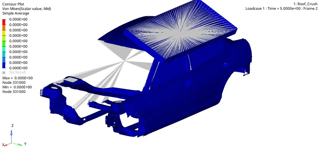
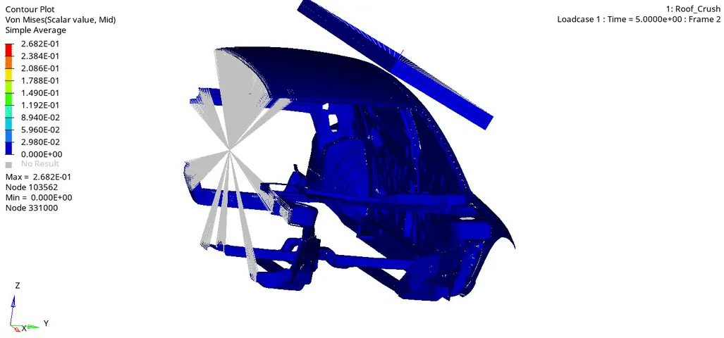
Equivalent plastic strain
Von-misses stress
ENERGY TIME DATA
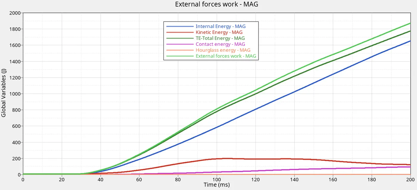
Note that for quasi static loads
Kinetic Energy/Total Energy ≤ 1
110/1790 = 0.06
KINETIC ENERGY = 110 joules
CONTACT ENERGY = 80 joules
INTERNAL ENERGY = 1650 joules
HOURGLASS ENERGY = ZERO
TOTAL ENERGY = 1790 joules
The flow of energy through the simulation was fairly as expected . The kinetic energy was gradually increasing and peaked half way through the simulation and began decreasing with significant increase in internal energy with time.
The contact energy which is the energy spent in moving penetrations out of the gap zone is almost constant with a slight increase. This is good as its supposed to be less than 0 to 5% of the total energy (89 joules).The contact energy is close but can be reuce by decreasing the gap value to reduce the penetrations.
Stabilization of hourglass is present
MASS CHANGE
It can be seen that the some mass was added during the simulation to account for the stabilization of the timstep. By specifying /DT/NODA/CST mass is added to the nodes with timestep decreasing in order to increase the timestep and keep it above minimum critical value. The total mass change is = 0.03%. This is way below 1% and can be acceptable whwn considering conservation of momentum.
TIME-STEP
Time-step right from the beginning maintained at 0.0005
FORCE VS DISPLACEMENT
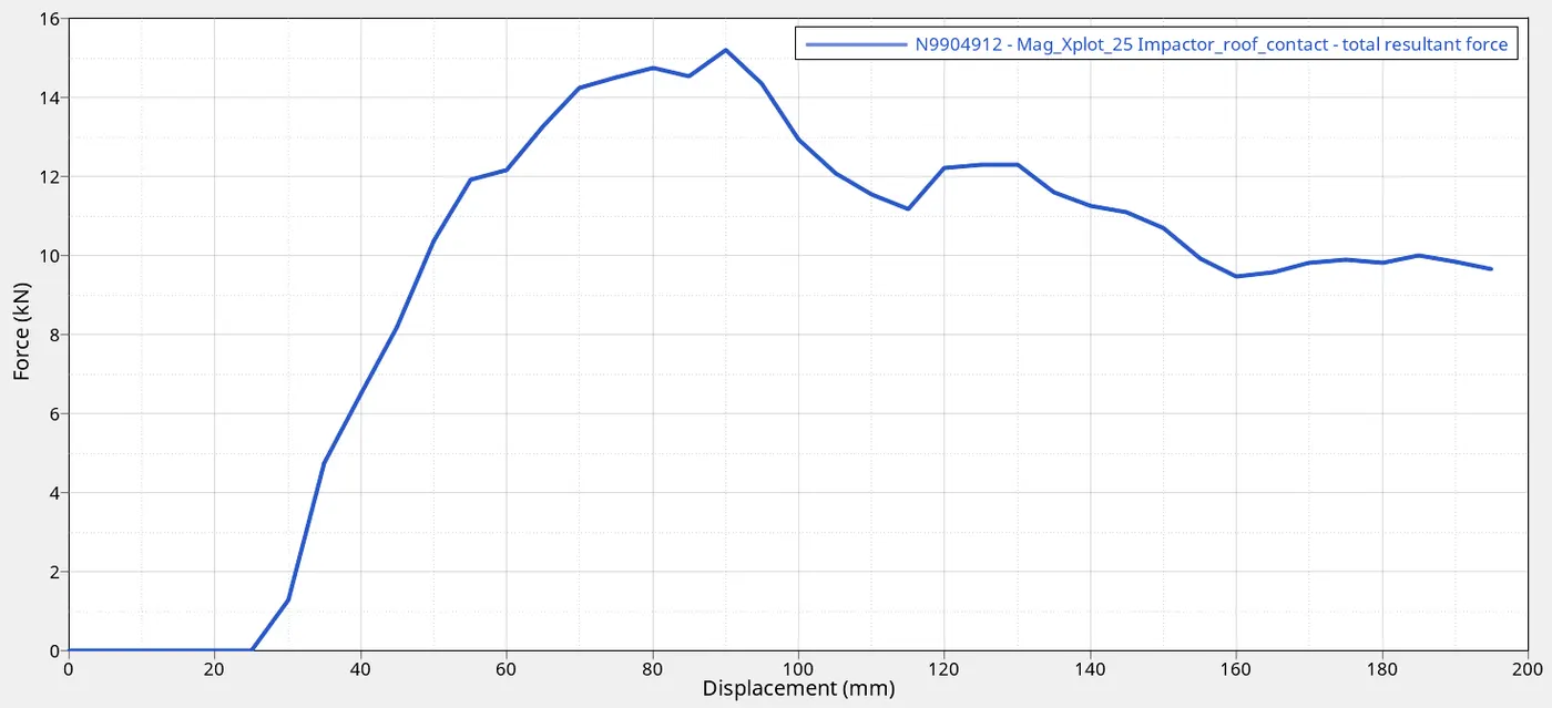
A cross plot is ploted to determine the force developed between the car and impacter and the displacement of the spring during the crush. As per the FMVSS 216 standard , the vehicle has to withstand a load higher than three times its weight. The weight of the vehicle 9557.94, 3 x 9557.94 =28.7 kN
Resisted forces from graph = 15kN
CONCLUSION
The simulation was succesfull withouit any major errors. It was determined that the vehicle was not able to resist more than 28.7kN. and does not pass the required vehicle safety standard.(FMVSS 216).
- The results can be improve by ensuring that all parts are connected properly to enable smooth transfer of forces
- The lack of strenght could be due to the absence of certain parts and poor reinforcement structures
- We can combine alloys of high strength and low weight alloys to strenghthen the A-pillar, Roof rails and B-pillar.