Week-6 Calculate the Stretch Ratio by comparing the ELFORM (-2,-1,1,2) with Ogden_Material Model.
LS DYNA – Ogden Material Modeling
By Enos Leslie
Mechanical Engineer
28th August 2021
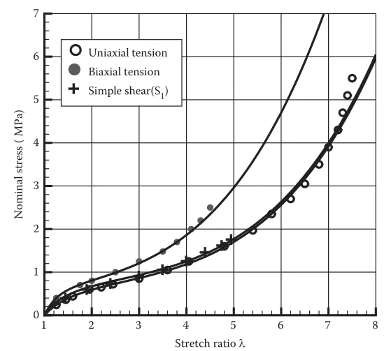
OBJECTIVE: Model a tensile test in the implicit deck with material Ogden and compare with the graph below. The Elform (1,-1, 2,-2) is varied and compared to the curve.
TASK:
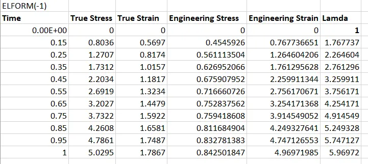
- An excel sheet with proper conversion and calculation of Stress/Strain and the Stretch Ratio for all the ELFORM.
- A proper image of the plot comparison of various ELFORMS against the Uniaxial Plot given in the challenge.
HINT
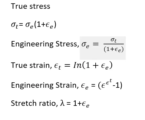
- LS-DYNA the output of stress and strains from Post Fringe Comp Stress/Strain is given as true stress and strains.
- Stretch ratio is defined as the ratio between the final length L and the initial length L0 of a component i.e. it is equal to (1 + engineering strain)
- My boundary condition should be relatable with the real-time boundary condition.
- I need to add *Database_Extend_Binary card and activate the STRFLG to get the strain data.
INTRODUCTION
The Ogden material model is a hyper elastic material model used to describe the non-linear stress–strain behavior of complex materials such as rubbers, polymers, and biological tissue. The model was developed by Raymond Ogden in 1972. The Ogden model, like other hyper elastic material models, assumes that the material behavior can be described by means of a strain energy density function, from which the stress–strain relationships can be derived.
PROCEDUE
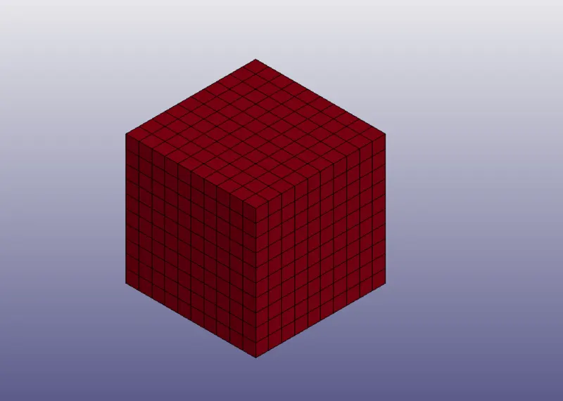
A new keyword is created in the deck. The material hyper elastic material is imported into the deck and a cube solid of dimension 10mm x 10mm x 10mm is created using shape mesher.
SECTION
A section card is defined for using SECTION_SOLID card.
- ELFORM: Element formulation options = 1 constant stress solid element (default)
- -1, fully integrated S/R solid intended for elements with poor aspect ratio efficient formulation.
- -2, fully integrated S/R solid intended for elements with poor aspect ratio accurate formulation
- 2, fully integrated S/R solid
MATERIAL
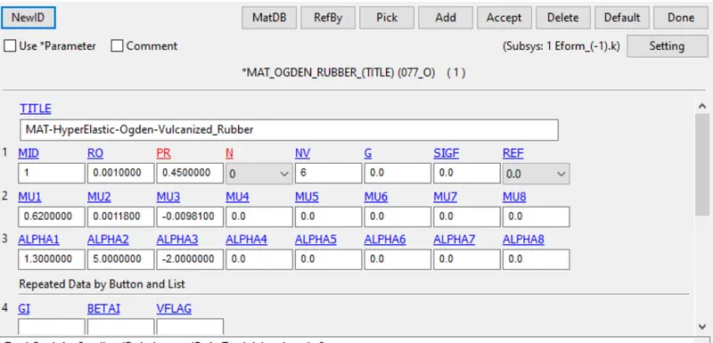
Material used in this is the Ogden hypereleastic model and it is imported into the deck. The variation and modeling of the constants and alpha values are not considered in this project.
BOUNDARY CONDITION
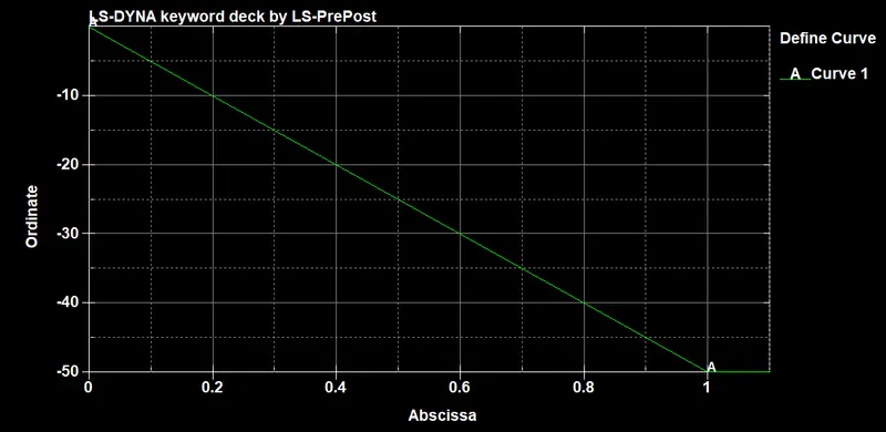
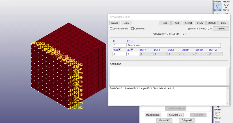
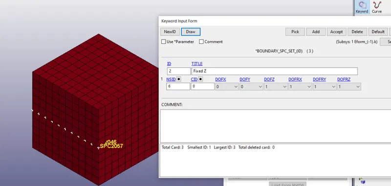
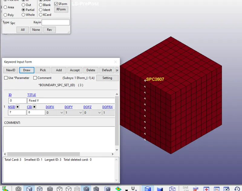
- PRESCRIBED MOTION SET is made to define the displacement boundary in the - X direction., a prescribed motion displacement of rigid body is selected. A load curve is defined below
FIXED NODES IN THE X AXIS
FIXED Z-AXIS
FIXED Y-AXIS
CONTROL IMPLICIT CARDS
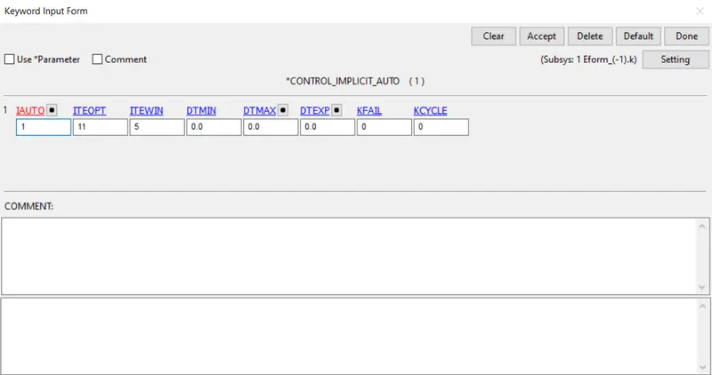
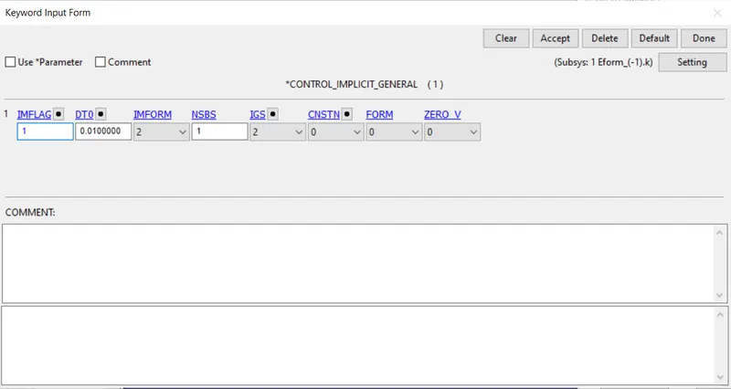
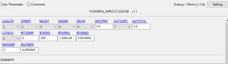
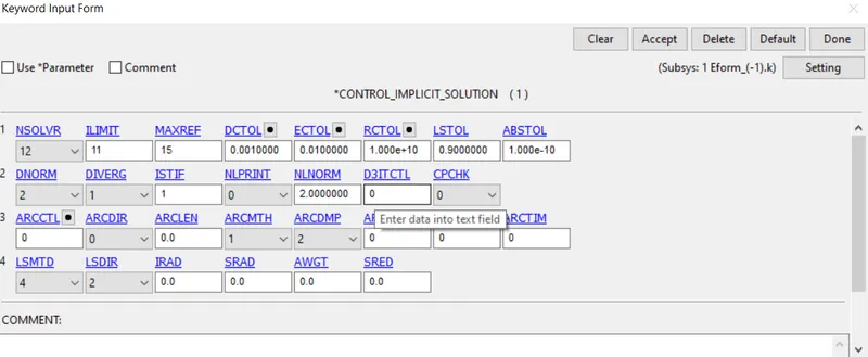
Termination time for the simulation is made for 1ms
OUTPUT RESULTS
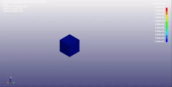
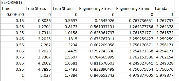
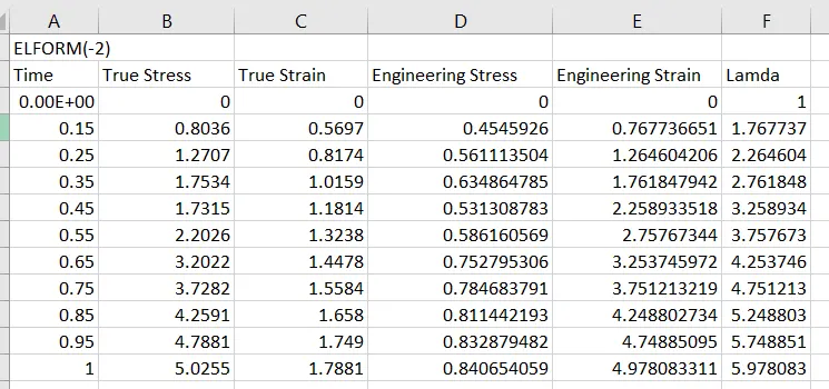
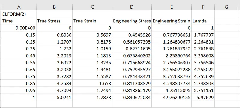
Data of true stress and strain values of all the different elforms were collected and the stretch ratio is calculated and plotted on a graph using excel. The output of stress and strains from Post Fringe Comp Stress/strain
PLOTS
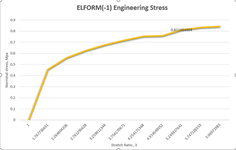
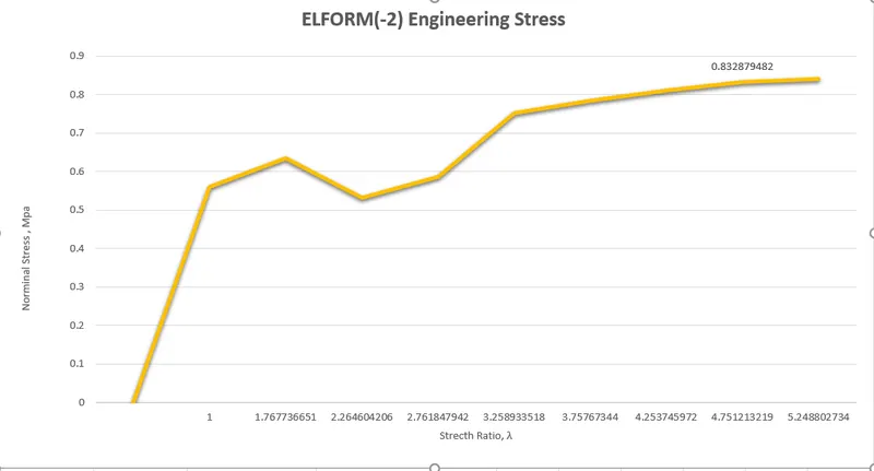
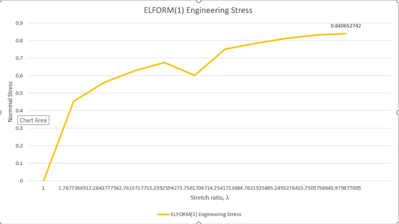
Below are plots of different element formulations stretch ration with nominal stress. This is to be compared to the main plot of the hyper elastic material.
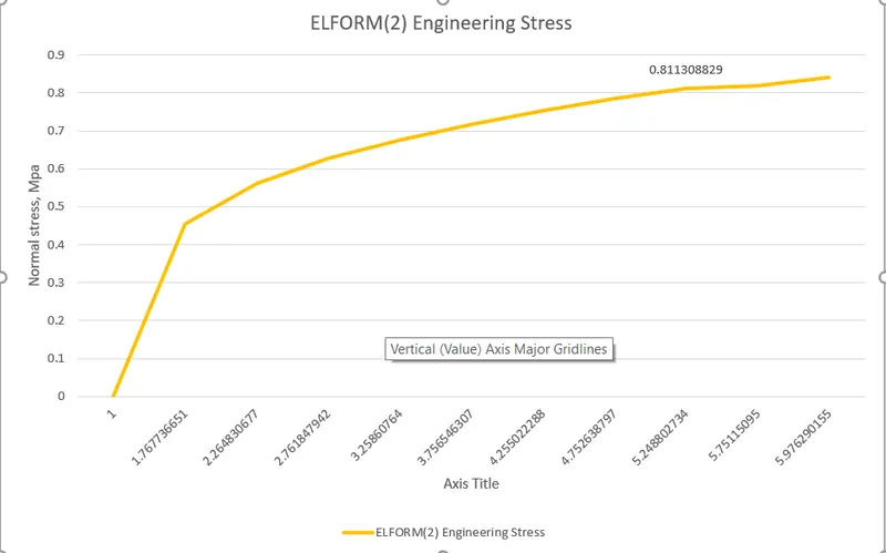
RESULTS AND CONCLUSION
From the results above all stresses for elform (1,-1, 2,-2) is computed and plotted. From the plots the highest nominal stress developed for a stretch ratio of 5 was seen in the elform (1) with a value of 0.84 Mpa. Comparing this to the plot, this is 1 Mpa lesser than the uniaxial stretch ration value of the Ogden material. Variation is seen because of the non-linearity of the materialThe stretch ratio values were successfully compared with the implicit solver results.