(ANSYS_P15) Machining with Planer Challenge
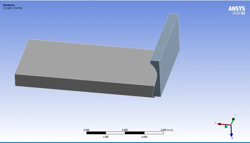
OBJECTIVE:Perform a Explicit dynamics analysis on machining planar model assembly in ANSYS Workbench.
- The Cutter is assigned a material of structural steel with a rigid stiffness.
- The workpiece is assigned an explicit material of steel 1060 with a flexible stiffness.
TASK
I would have to perform an explicit dynamics simulation to find out the Equivalent Stress, Total Deformation and also insert a User defined result to calculate the temperature of the body. I need to perform this for 2 cases. One will be with a cutting velocity of 20000mm/s and the other will be with a cutting velocity of 15000mm/s.
CONNECTIONS
- No contacts are defined in explicit analysis.
- We just assign frictionless contact to all bodies in Body Interactions.
MESHING
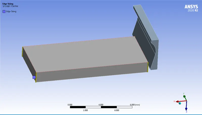
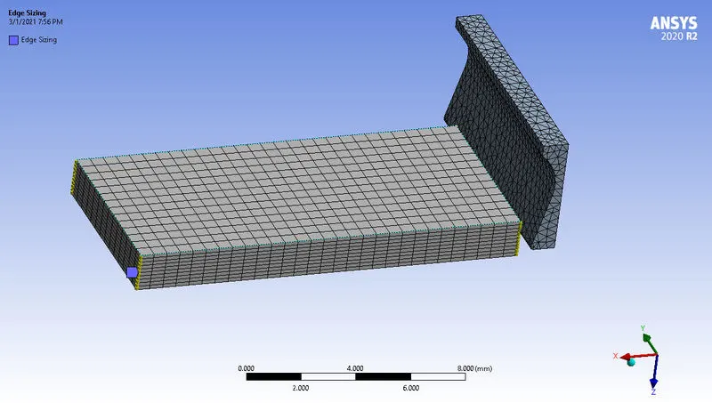
- A meshing method is assigned to the cutter with element method tetrahedron.
- An edge sizing of 10 divisions is specified in the workpiece.
ANALYSIS SETTING
- End time : 0.00075s
- Maximum number of cycles :100000000
- Energy error limit : 0.1
BOUNDARY CONDITIONS
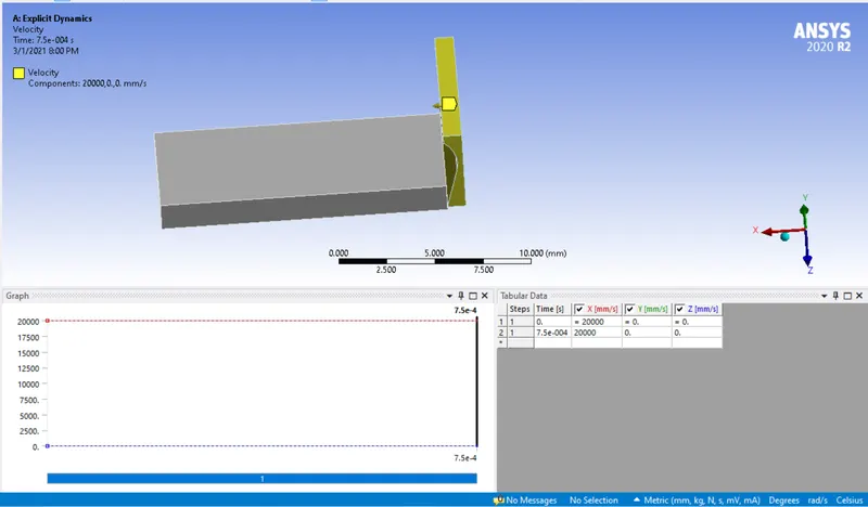
- A velocity is assigned to the tool
- A bottom surface of workpiece is fixed
- Case_1 : 20000mm/s
- Case_2 : 15000mm/s
OUTPUT REQUEST
CASE_1
- Total Deformation
- Equivalent Stress
- User defined temperature
CASE_2
- Total Deformation
- Equivalent Stress
- User defined temperature
RESULTS
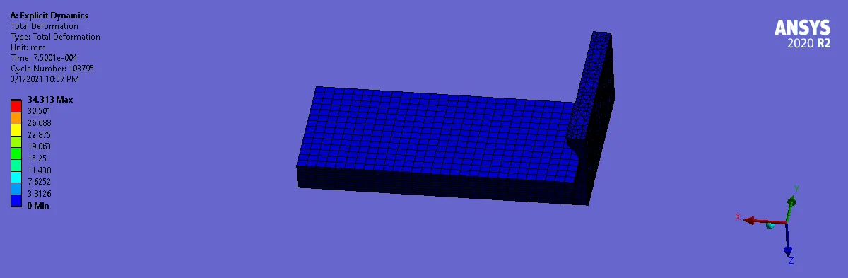
- Total Deformation (34.31mm)
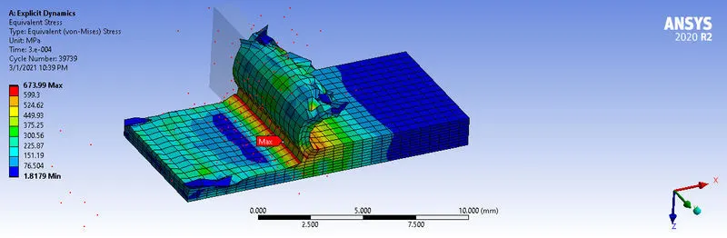
- Equivalent Stress (673.99 Mpa)
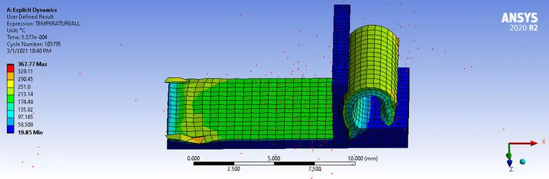
- User defined temperature (367.77 Celsius)
CASE_2
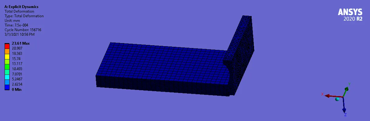
- Total Deformation (23.6mm)
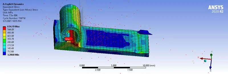
- Equivalent Stress (634.19 Mpa)
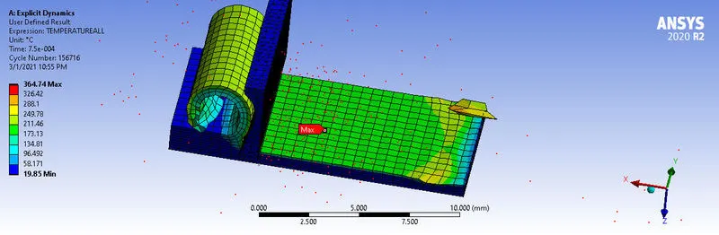
- User defined temperature (364.74)
DISCUSSION
| CASE | DEFORMATION(mm) | STRESS (Mpa) | TEMPERATURE(CELSIUS) |
| 1 | 34.31 | 673.99 | 367.77 |
| 2 | 23.60 | 634.19 | 364.74 |
The following was observed between both cases
- The deformation of the second case was lower than that of the first. This is due to the set reduction velocity of 15000mm/s. The tool moved slower than the first case and could not complete the full cut for an end time of 0.00075s
- The stresses developed was maximum in both case around the tool cutting contact which is most stresssed during the operation. The second case developed slightely lower stresses due to the change in speed of the cutting tool.
- The temperatur also varied slightely on the workpiece with the lesser being on the case 2 workpiece. The reduction of speed caused a reduction in temperature , stresses and deformation.
CONCLUSION
This task was simulated succesfully and the effect of cutting tool speed was analysed and deduced.