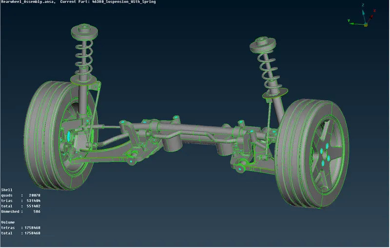
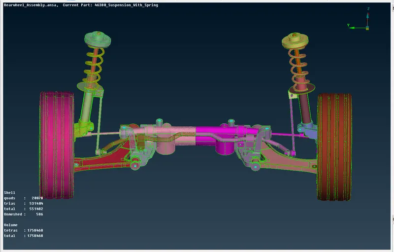
(ANSA_PROJECT_2) MESHING AND CREATING CONNECTIONS FOR VEHICLE REAR SUSPENSION
OBJECTIVE : Meshing and assigning neccessory connecttions to a vehicle rear suspension
PROCEDURE
- Importing of the model into Ansa
- Making geometry checks and assigning PID's to each component
- Generating volume mesh on geometries with large thickness
- Generating midsurface and mesh for parts with uniform and small thickness
- Give connections on the geometry for NVH analysis using nastran deck.
IMPORTING MODEL
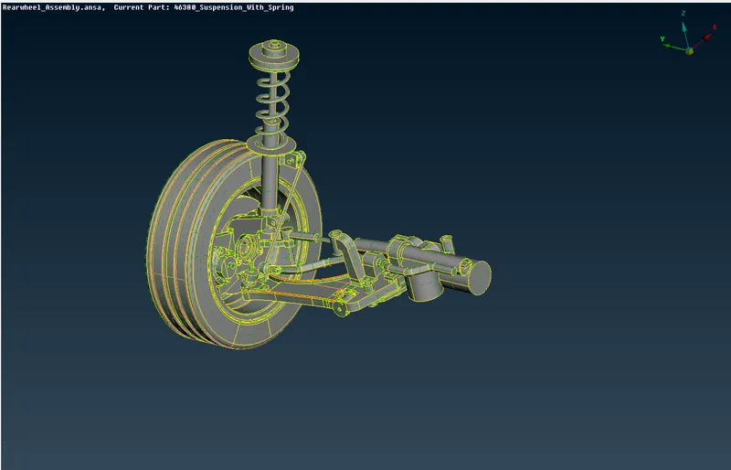
The model is imported into the ansa GUI.
- When the geometry is first opened in Ansa, it can be seen as a single entity from the image below
GEOMETRY CHECKS
- The whole 3D componenent is fixed by applying Topo
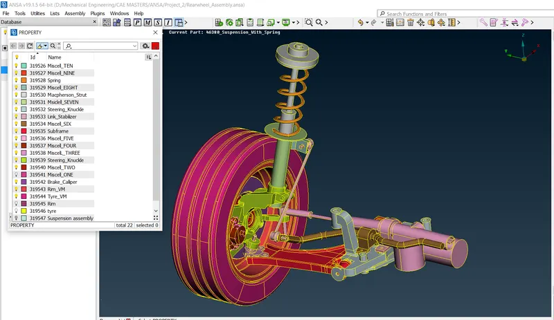
- PID's are assigned to every part to differenciate with property
- An automatic geometry check is made on all of these lock screens to check for errors in geometry surfaces by specifying, ( single,triple and double cons , cracks, collapse cons etc). It can be seen below the results.
- Some of the components are not suitable enough for extraction of midsurface so it is meshed with 3D Tetra element instead .
- But first the surface cons are controlled in order for the surface to pass element lenght criteria.
VOLUME MESHING
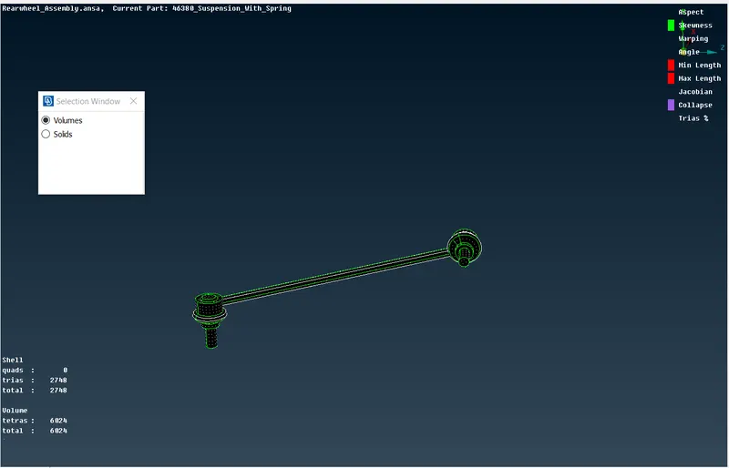
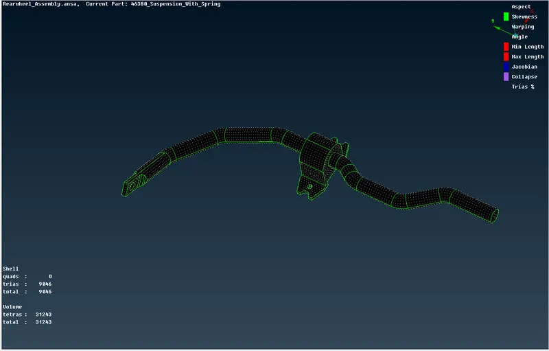
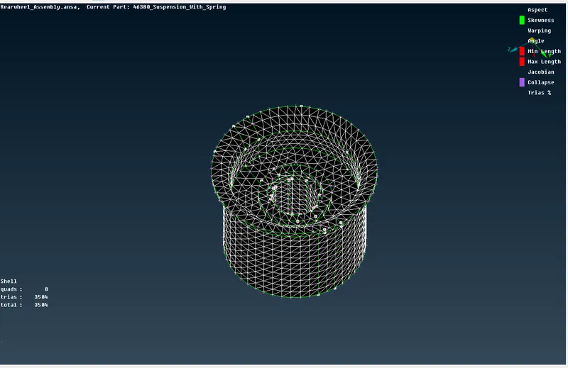
- Some of the components are to be meshed with tetra elements
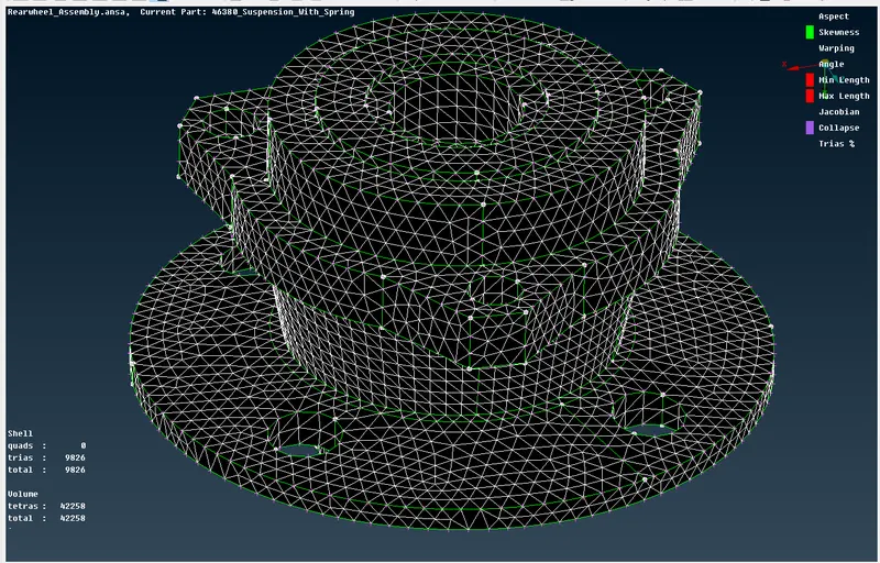
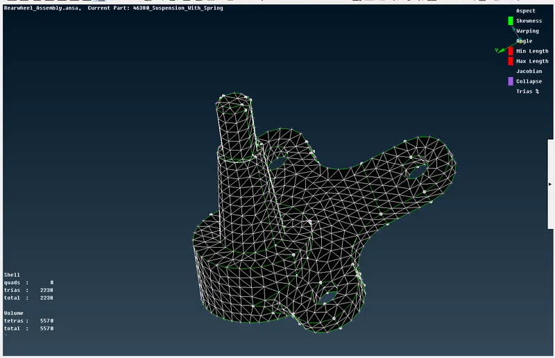
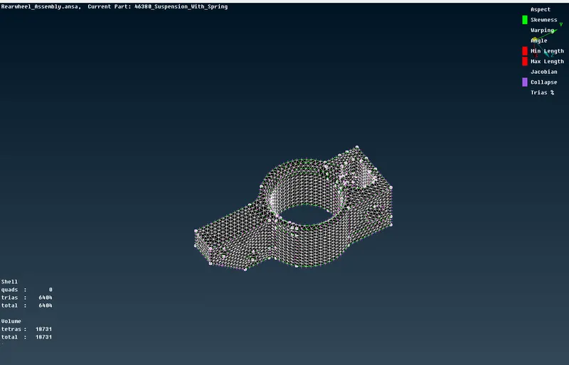
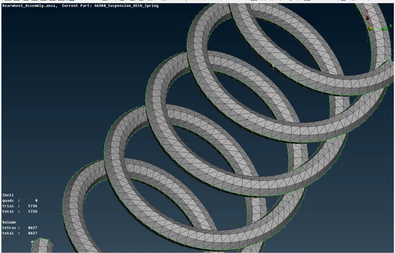
- First the surface is meshed with Tria elements and then later transformed to a volume mesh
- Tetra rapid is used to convert the meshed 2d to 3d after a volume is defined.
- There are four components in total each is meshed separatly and defined
- Otho trias where used at surface with greater bends whiles tria where used of straight faces.
Quality required for volume mesh is listed below
Quality Criteria for Tria Elements (Tyre and Rim):
|
S.No |
Quality Criteria |
Value |
|
1 |
Target/Average length |
6.5 |
|
2 |
Minimum Length |
5 |
|
3 |
Maximum Length |
10 |
|
4 |
Skewness |
45 |
TYRE
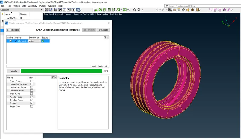
Geometry checks on the tyre before meshing
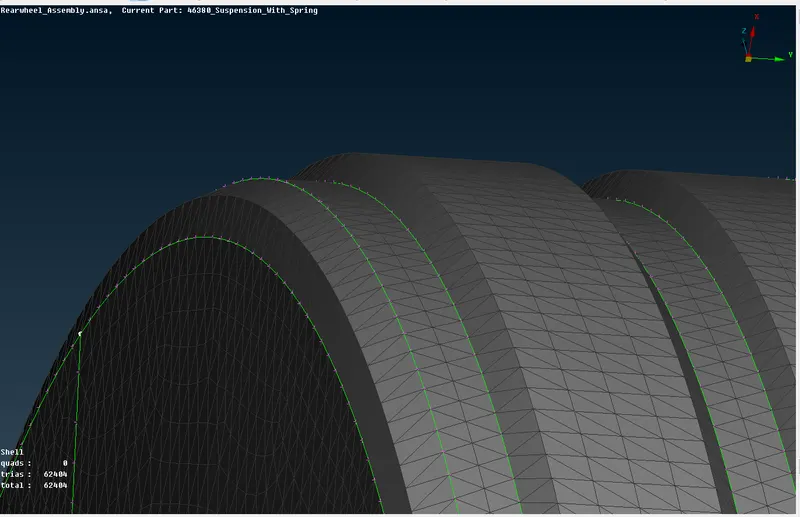
Meshing the tye with tria and ortho tria shell elements
- The meshed 2D surface before conversion is made with a quality of minimum and maximum length of 5 and 10 respectively.
- The 3D tetra elements must be void of any kinks and un even surfaces.
Also the 3D volume meshed needs to be checked for tet collapse of 0.2. All the elements which failled the test were manualy fixed by moving the nodes in a manner not to distort the mesh pattern on the component surface.
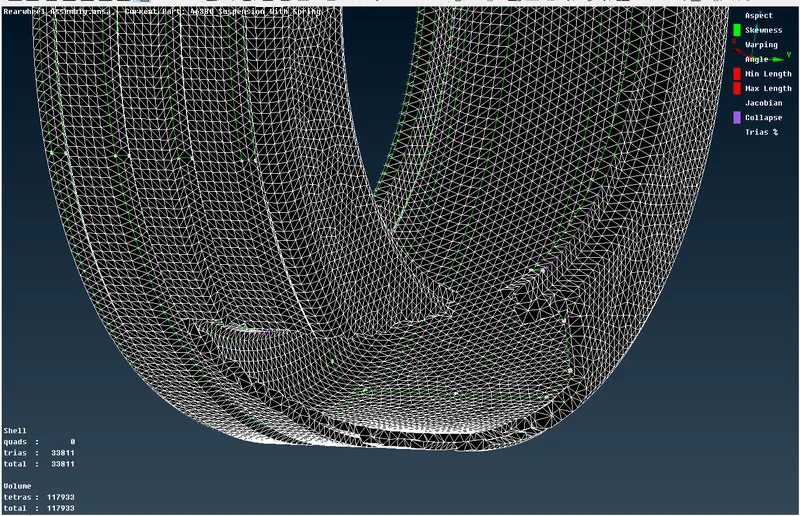
Volume meshed Tyre with zero tet collapse
RIM
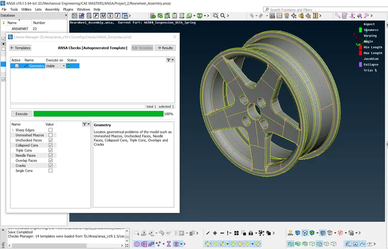
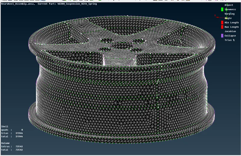 Geometry checks on the rim before meshing
OTHER VOLUME MESH COMPONENTS
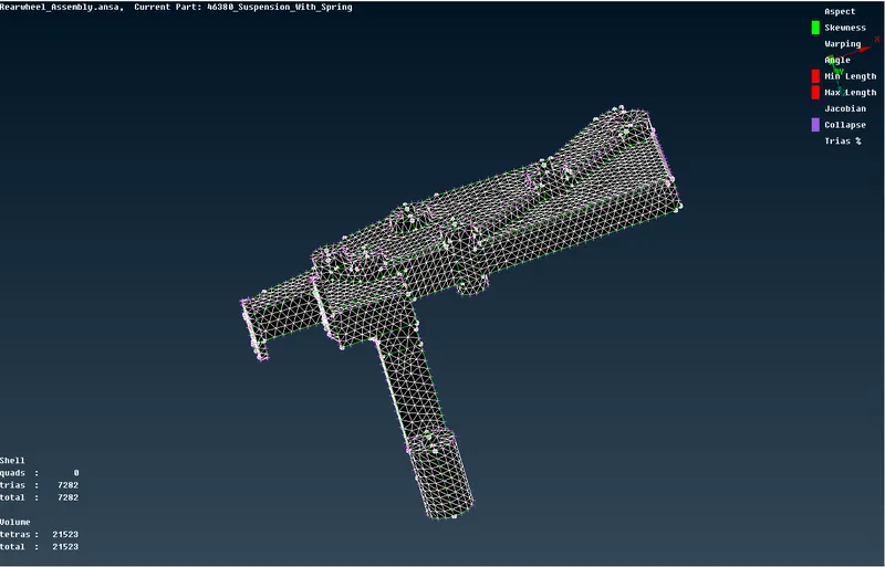
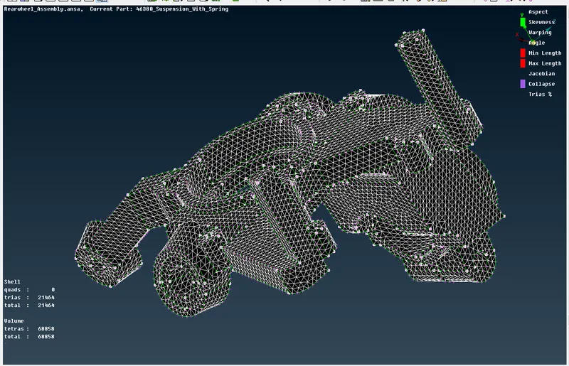
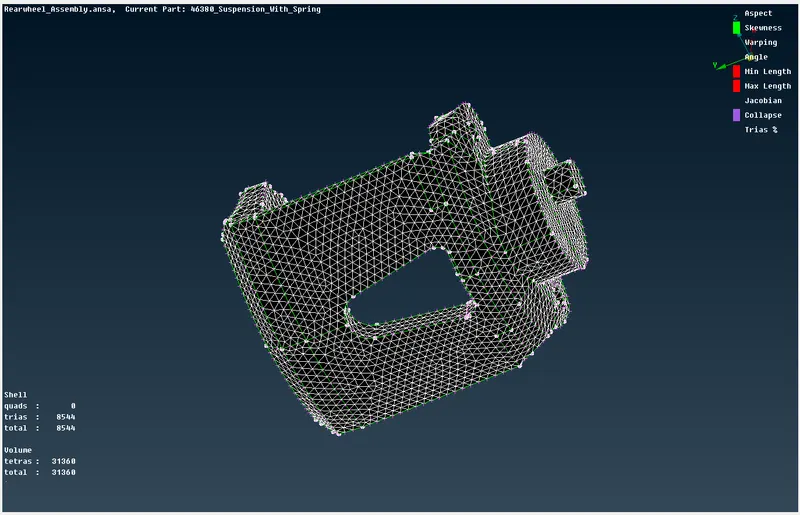
Some other components which was meshed using tria elements are shown below
Quality criteria for Tria (For other components):
|
S.No |
Quality Criteria |
Value |
|
1 |
Target/Average length |
4 |
|
2 |
Minimum Length |
2 |
|
3 |
Maximum Length |
6 |
|
4 |
Skewness |
45 |
Common Quality Criteria for Tetra elements are:
|
S.No |
Quality Criteria |
Value |
|
1 |
Tet-collapse |
0.2 |
Steering Knuckle
Generation of midsurface
EXTRACTION OF MIDSURFACE
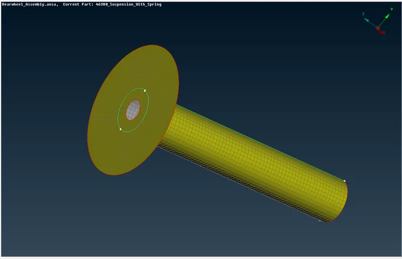
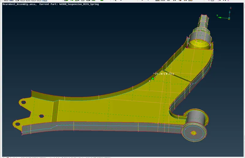
- Midsurface of the components are created in order to make a shell mesh on the components.This is because it is more efficient and time saving than using 3D meshing.
- The midsurface can be generated automatically and manually.This task, i chose to use the manual option. The "offset" function is used to offset the surfaces of all the components by a distance which is equall to half the thickness of the components. After offsetting, the surfaces are all joined together using "topo".
- The midsurface of all components are generated separately and saved with specific PID's.
- The final geometry check is done to make sure there are no errors in the midsurface generated.
MESHING OF COMPONENTS
- Before meshing is done, all geometries must be cleaned up in order to control the rquired mesh sizes.
- For a mesh of target element size of 4, all cons and lines which form spaces with length below 2mm must be controlled. In a sense that, we must re-edit these cons to increase their sizes to 2mm and above.
- This can be done by using the perimeter length of 4mm across all components and carefuly checking for cons and edges lesser than 2mm to be editted.
- Editting is done by using the "cut" function to create cons and remove cons.
- All circles should be captured with even number of elements and they should be rotated and maked to position them parallel.
- After clean up, meshing can be started
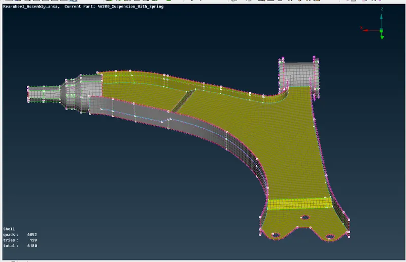
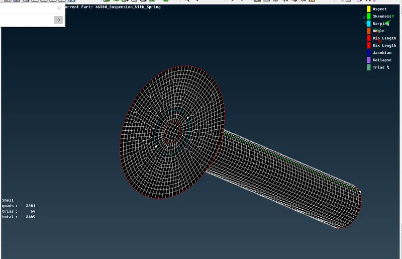
- The element mesh size is set to 4mm and mixed element type is chosen
- All components are meshed using this mesh type and considering the following criterias for optimum mesh flow
- All rotating quads should be eliminated from the mesh
- Minimum tria elements should be present
- All opposite tria elements should be combined to form quads
- No tria elements should be in contact with any feature lines
- Tria elements should be well spaced from each other and should not be in contact with each other.
- No tria elements should be present at the edges of the components
Quality criteria for Mixed elements (For Midsurface only):
|
S.No |
Quality Criteria |
Value |
|
1 |
Target/Average length |
4 |
|
2 |
Minimum Length |
2 |
|
3 |
Maximum Length |
6 |
|
4 |
Aspect |
3 |
|
5 |
Warpage |
15 |
|
6 |
Skewness |
45 |
|
7 |
Jacobian |
0.7 |
|
8 |
Minimum Quad Angle |
45 |
|
9 |
Maximum Quad Angle |
135 |
|
10 |
Minimum Tria Angle |
30 |
|
11 |
Maximum Tria Angle |
120 |
ASSIGNING OF CONNECTIONS
- Depending on the mechanisim and its fnction these connections are used in this model (Spot weld, Bolt,Rbe2 , Rbe3-cbush-rbe3)
BOLT
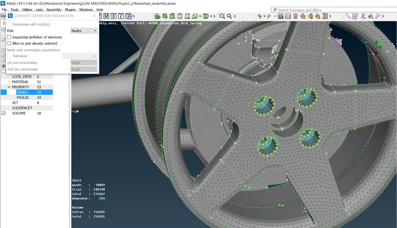
- Bolt connection is created automatilcally using a coveted 3D point to a bolt and setting the necessory parameters.
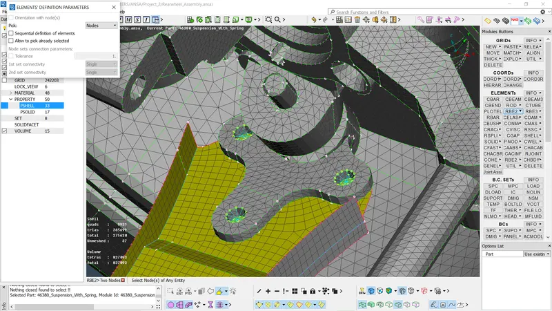
- In this model manual bolts was created using two many nodes rbe2 selection on two holes and connecting both master with Rbe2 two node selection
RBE2
- This one dimension links are created to connect opposite holes together
SEAM WELD
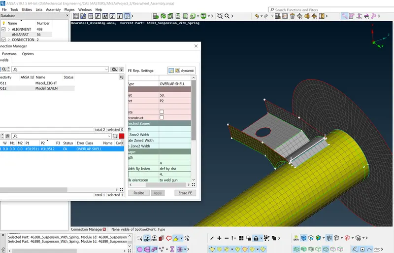
Overlap seam weld is used to connect two overlapping shell components by creating a seam line and defining the weld properties
Mirror Components
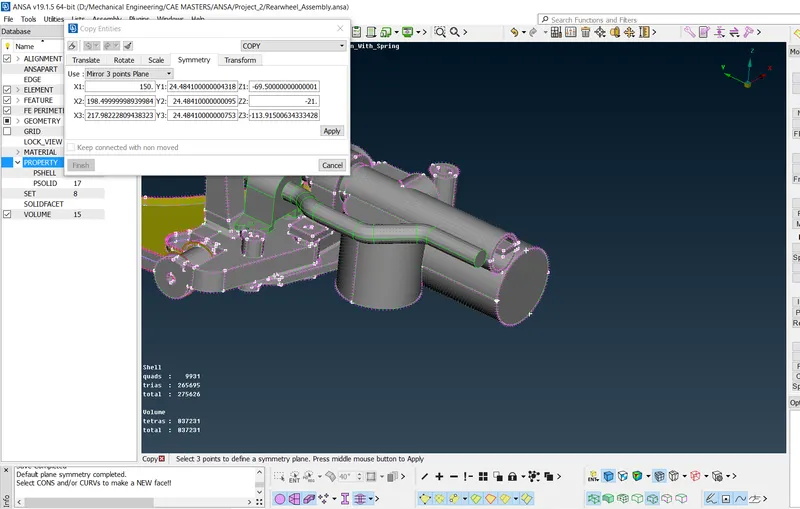
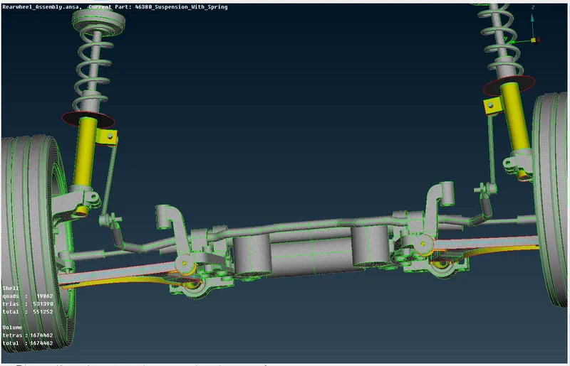
All components are mirrored by selecting thre points to define the plane
CONCLUSION
The rear vehicle suspension is succesfully meshed with neccessory connections. This model is ready to be used in the nastran deck for vibration analysis.