ANALYSIS OF A FAILURE ALUMINIUM PLATE USING MATERIAL MODELS (LAW_1,LAW_2,LAW_27,LAW_36) AND JOHNSON FAILURE CARD IN RADIOSS
OBJECTIVE: It is very important to define properly the plasticity of material and failure accurately when modeling FEA. This project involves the experimental analysis and comparison of certain material laws and failure to analyse their differences and how accurate their failure and results are in terms of certain engineering quantities. Their failures Below are the material laws and failures to be compared
- LAW_1 (ELASTIC)
- LAW_2 (ELASTO-PLASTIC)
- LAW_27 (BRITTLE)
- LAW_36 (ELASTO-PLASTIC WITH USER DEFINED FUNCTION)
PROCEDURE
Unit : mm g ms
A plate is impacted by a rigid ball with a velocity of 10mm/ms. An aluminium plate is used with shell and material properties below
MATERIAL (ELASTO-PLASTIC )
- Card image = M2_PLAS_JOHNS_ZERIL
- Initial density (rho) = 0.0028g/mm3
- Young Modulus (E) = 71000Mpa
- Poisson ratio (u) = 0.3
- True yield stress (a) = 290Mpa
- Hardening Modulus (UTS) (b) = 562.3
- Hardening Exponent (n) = 0.63
- Maximum plastic strain for failure (EPS_p_max) = 0.151
- Maximum stress (sig_max0) = 425Mpa
SHELL PROPERTIES
- CARD IMAGE = P1_SHELL
- Ishell = QEPH shell formulation
- Ismstr = Full geometric nonlinearity with possible small strain formulation
- Ish3n = 2
- Ithick = 1
- Iplast = 2
CASE_1
| FAILURE CARD | JOHNSON FAILURE CARD |
| EPS_p_max | 0.151 |
| XFEM | 0 |
JOHNSON FAILURE CARD
| ifail_sh |
2 |
| D1,D2,D3 |
0.11,0.8,-1.5 |
| Xfem |
0 <elements are deleted when strain reaches 15%> |
| Time of simulation | 01m:51s |
| Total number cycle | 49480 |
CASE_2
Using the same material and shell properties the only differece from case_1 is seen below
JOHNSON FAILURE CARD
| ifail_sh |
1 |
| D1,D2,D3 |
0.11,0.8,-1.5 |
| Dadv |
1 |
| Xfem |
1 <elements are cracked when strain reaches 15%> |
| Total number cycle |
49397 |
| Time of simulation |
01:42 |
RESULTS OF COMPARISON BETWEEN CASE_1 AND CASE_2
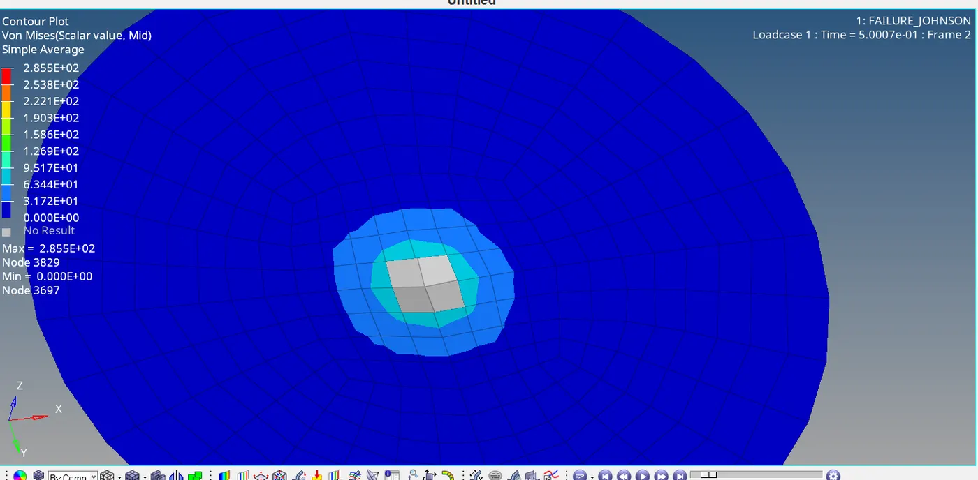
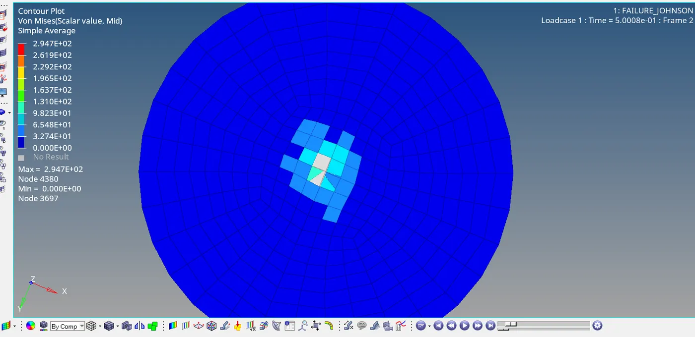
Case_1(left) it can be seen how the elements are deleted due to XFEM set to 0.
Case_2(right) it can be seen how the elements are cracked due to XFEM set to 1
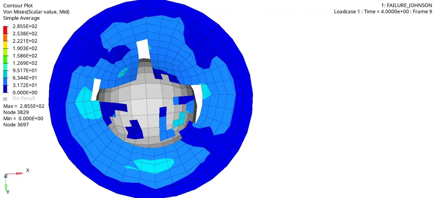
Case_1(left) it can be seen how the elements are shattered and deleted at 15% plastic strain.
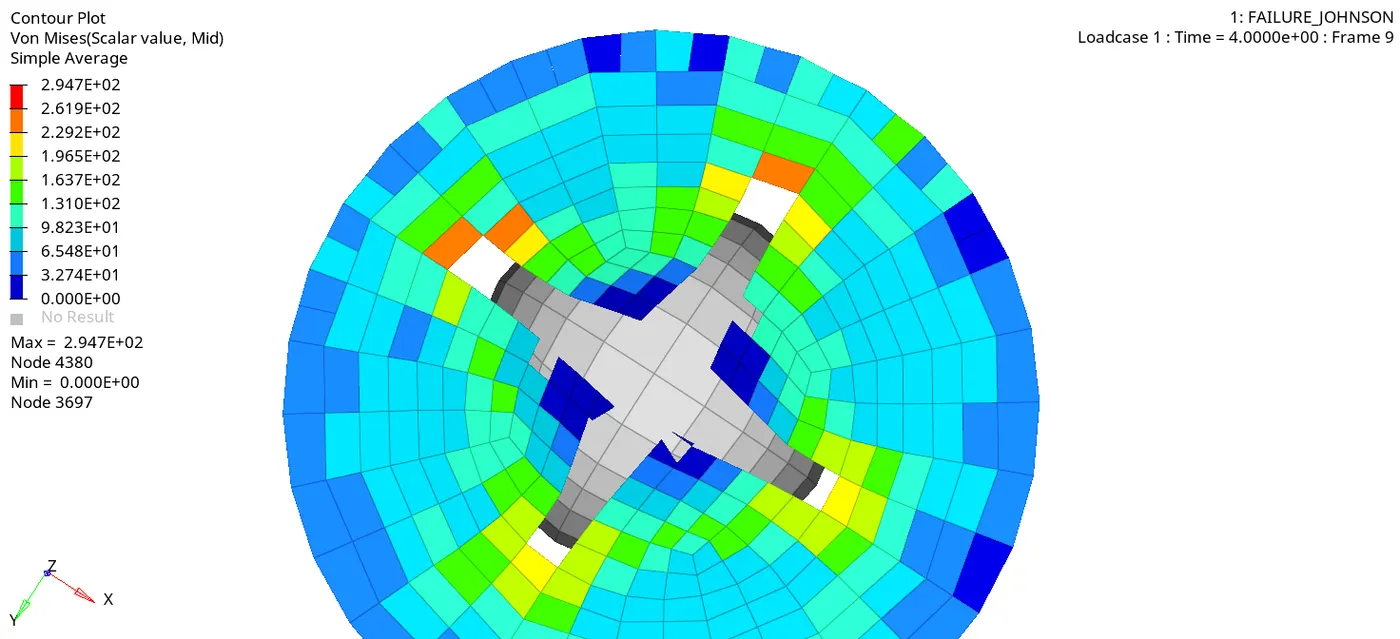
Case_2(right) it can be seen how the elements are cracked at 15% plastic strain and energy is dissipated through cracks.
KINETIC ENERGY
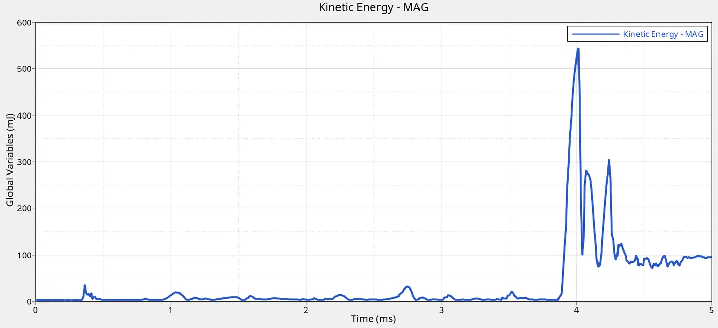
Case_1(left) it can be seen at 4ms there is the maximum kinetic energy which occurs when more elements are shattered and deleted.
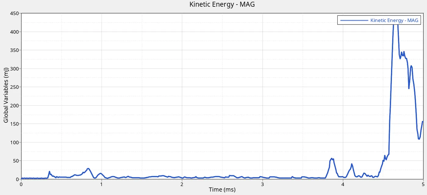
Case_2(right) it can be seen that at 4ms more kinetic energy low compared to case_1 but it increases at 4.4ms where the kinetic energy increase due to the cracking and energy is dissipated.
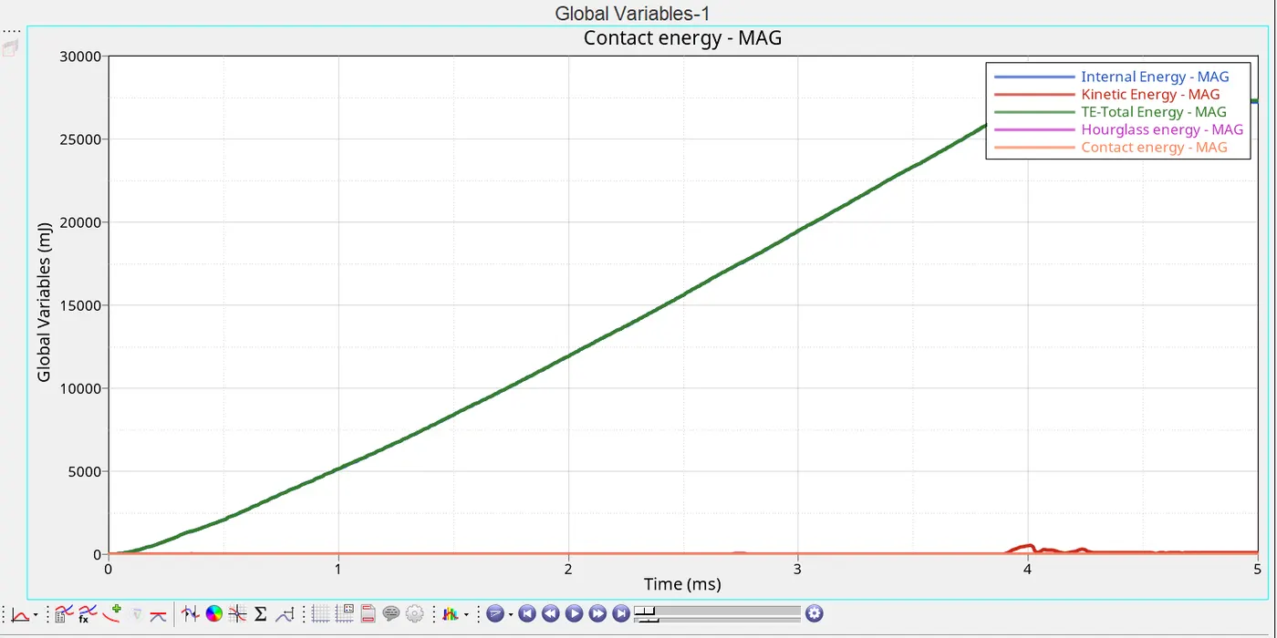
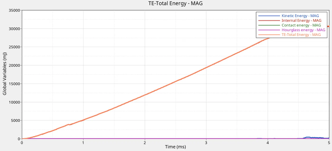
For both cases, the internal energy is increasing linearly as the ball crushes the plate. So is the total energy. The hourglass and contact energy remains constant at 0 due to its high stability
The kinetic energy is the only difference and was explained above.
| CASE | MASS ERROR |
ENERGY ERROR <Less than is acceptable 15% GOOD> |
| 1 | 0.00 | 0.2 |
| 2 | 0.00 | 4.0 |
CASE_3
| FAILURE CARD |
NA without failure card, the material is not able to simulate compression under forces . |
| EPS_p_max |
0.151 (elements fail at 15% plastic strain) |
| Total number cycle |
49405 |
| Time of simulation |
01:47 |
Case_3 all material and property remains the same except this time Johnson failure card is removed.
CASE_4
Case_4 there is no specified maximum plastic strain value so the material is not going to be deleted at 15% plastic strain.
| FAILURE CARD | JOHNSON FAILURE |
| EPS_p_max | 0 |
| XFEM |
0 (elements deleted at maximum plastic stress |
| Ifail_sh |
2 (The shell is deleted or cracked when for all integration points or layers. |
| Total number cycle |
49304 |
| Time of simulation |
01:46 |
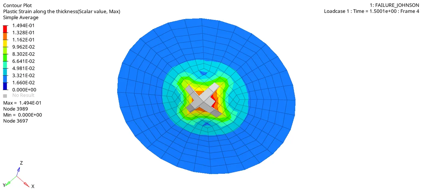
CASE_3 ABOVE
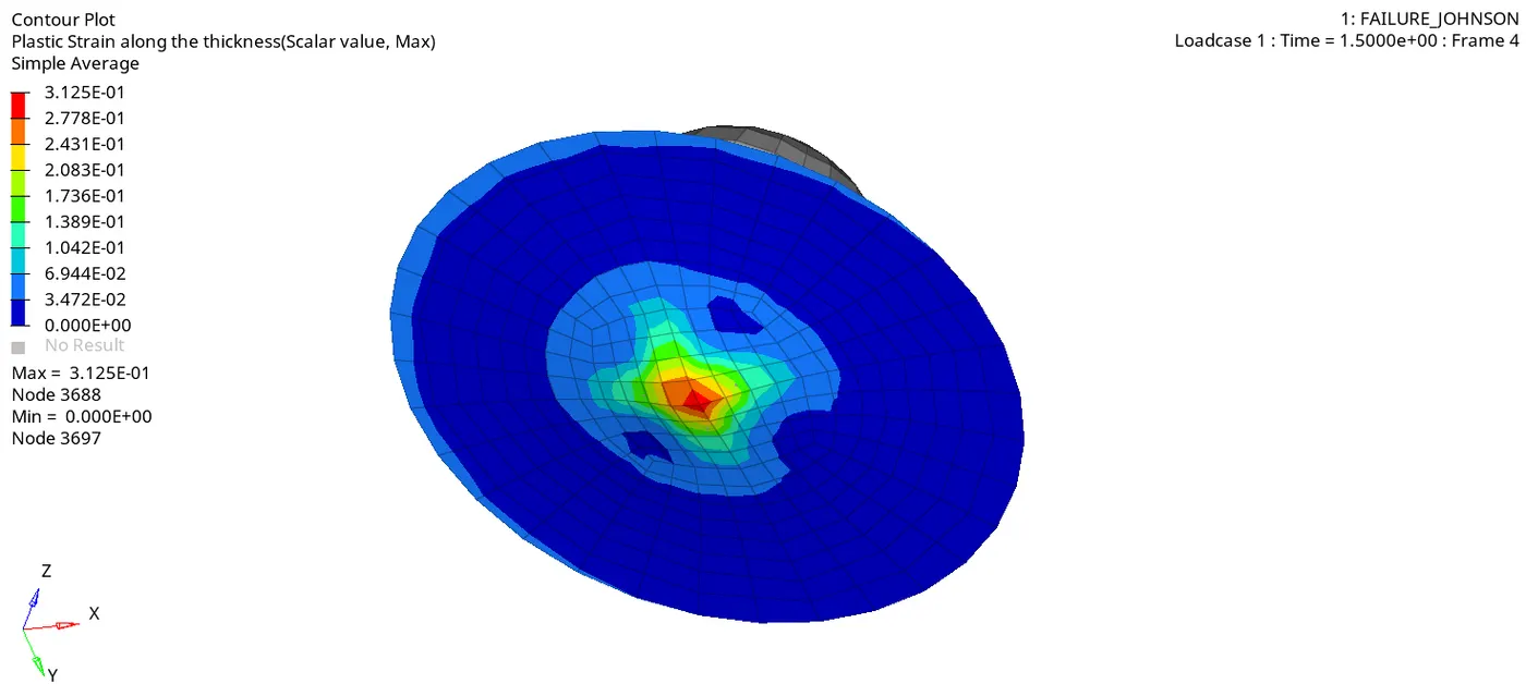
CASE_4 ABOVE
RESULTS OF COMPARISON BETWEEN CASE_3 AND CASE_4
Elements in case_3 can be seen that elements are deleted very early at the same time compared to case_4.That means that the elements in case_3 are deleted at 15% maximum plastic strain, whereas case_4 at the same time element cannot be deleted because eps_p_max was not specified .But case_4 element are deleted after the maximum stress value is reached at the very last integration point because ifail_sh =2 .
KINETIC ENERGY
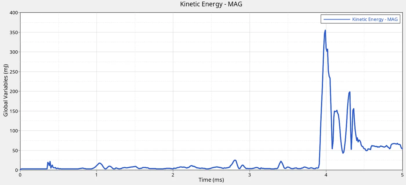
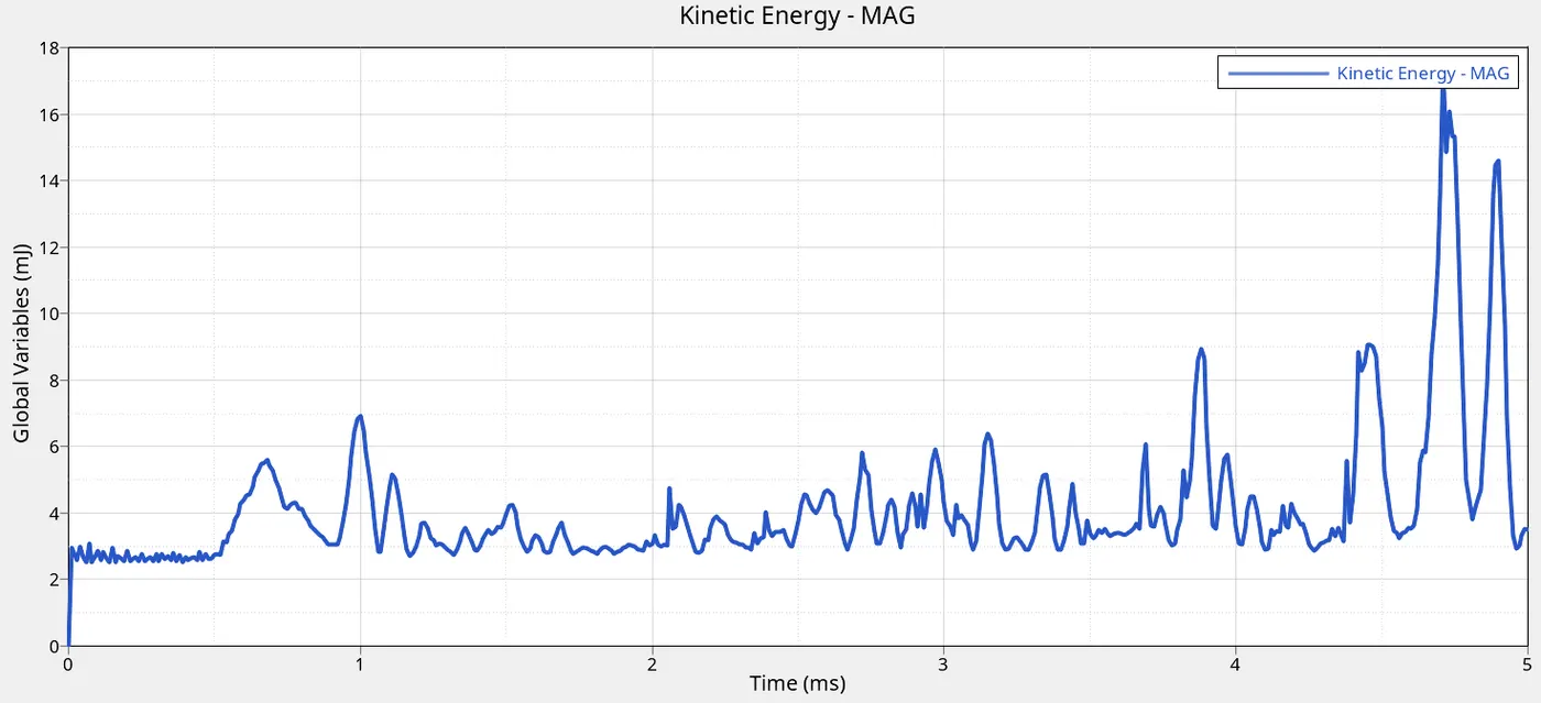
Case_3(left) it can be seen at 4ms there is the maximum kinetic energy which occurs when more elements are shattered and deleted.
Case_4(right) it can be seen that the kinetic energy low compared to case_3 because less elements are deleted at certain compared times and the elemnts are being deleted slowly and gradually. More plastic strain occurs in case_4.
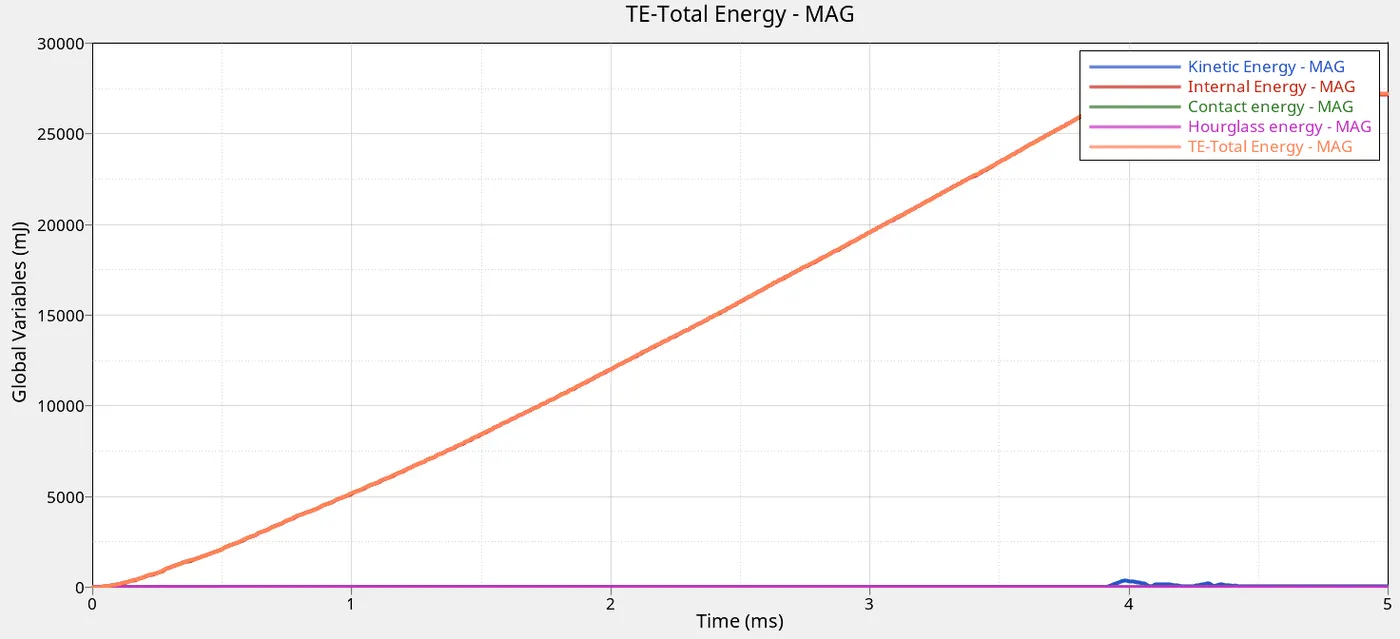
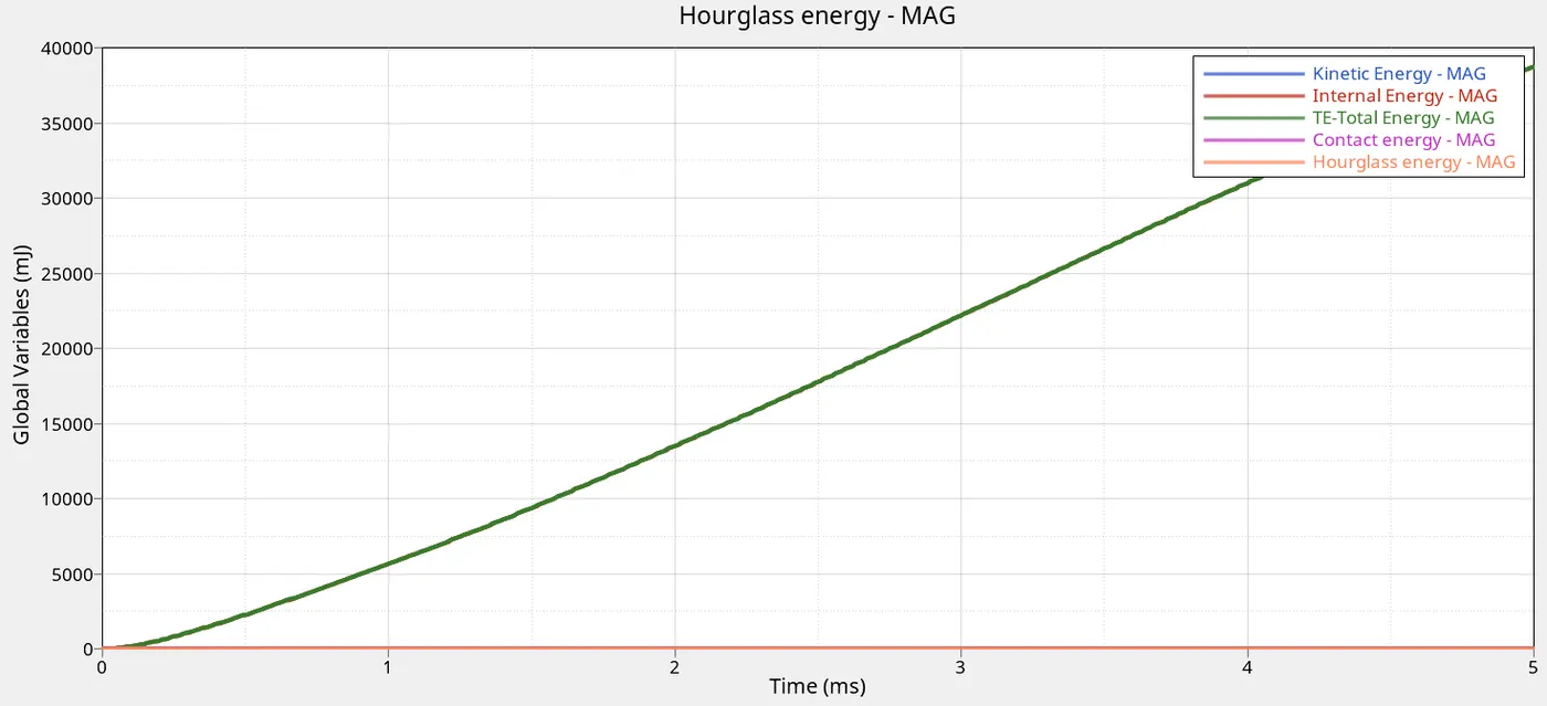
For both cases, the internal energy is increasing linearly as the ball crushes the plate. So is the total energy. The hourglass and contact energy remains constant at 0 due to its high physical stabilisation.
The kinetic energy is the only difference and was explained above.
| CASE | MASS ERROR |
ENERGY ERROR <Less than is acceptable 15% GOOD> |
| 3 | 0.00 | 0.8 |
| 4 | 0.00 | 1.1 |
CASE_5
|
MATERIAL CARD |
LAW_1 (Elastic) |
|
Initial density (rho) |
0.0028g/mm3 |
|
Poisson ratio (u) |
0.3 |
| Time of simulation |
01:46 |
|
Young Modulus (E) |
71000Mpa |
| Total number cycle |
47949 |
| Mass error |
0.00 |
| Energy error |
1.8% |
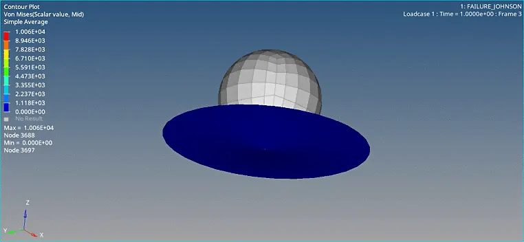
Case_5 simulation shows a perfect elastic material with no plastic deformation. This is due to the material law_1 selected.
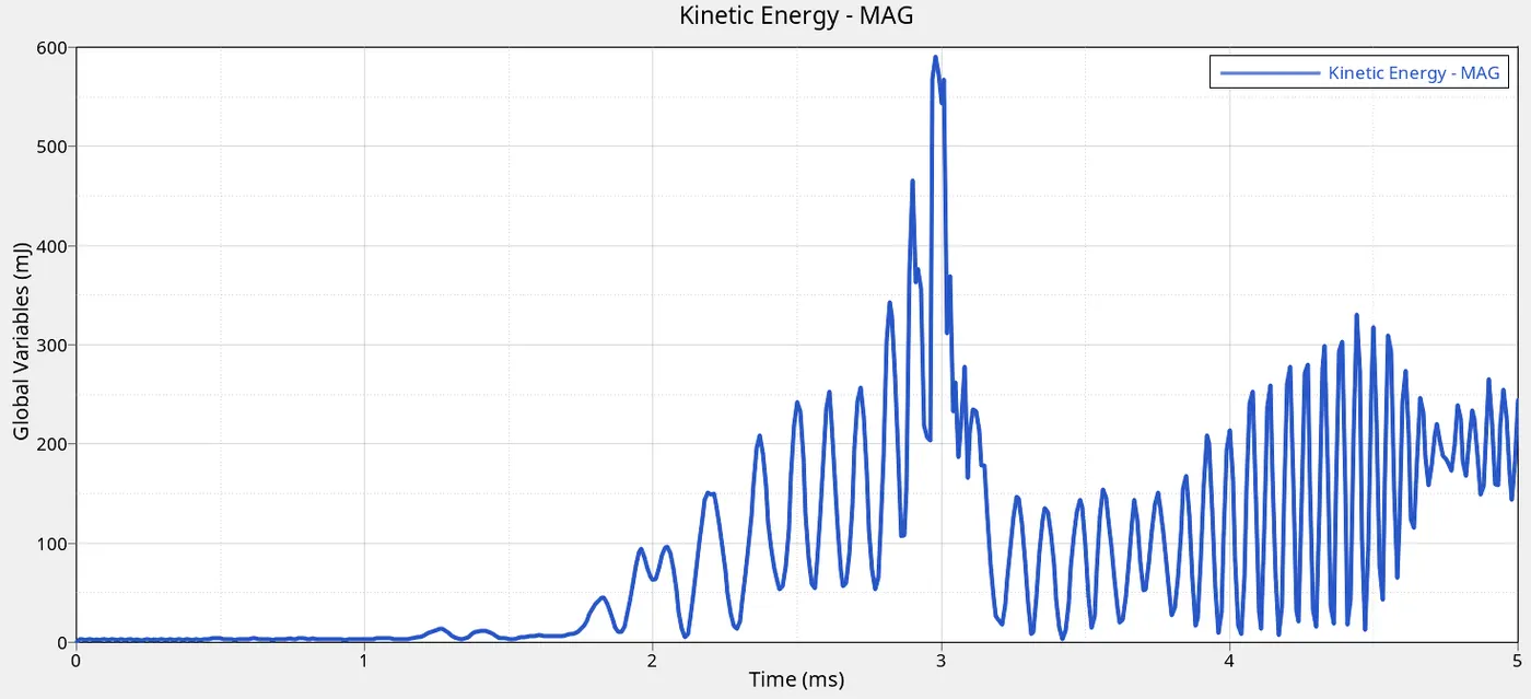
Kinetic energy shows the fluctuating curves or noise due to the elastic nature of the material. Energy is absorbed and not dissipated so there is a resistance which decelerates the ball little as the kinetic energy is increasing. Due to the elastic nature of the material without plastic deformation it is expected that the kinetic energy absorbed would be conserved and thus the material would return to its starting position.
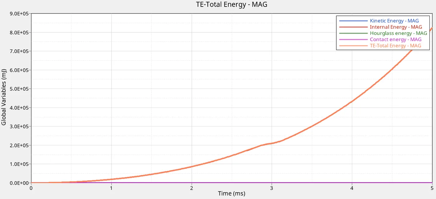
The internal energy is increasing linearly as the ball crushes the plate. So is the total energy. The hourglass and contact energy remains constant at 0 due to its high physical stability
CASE_6
This is an elasto-plastic Johnson-cook material model with an orthotropic brittle failure model.
|
MATERIAL CARD |
LAW_27 (plast_BRIT) |
|
Eps_t1 |
0.14 Tensile failure strain at which stress starts to reduce |
|
Eps_m1 |
0.15 (The end of tensile damage the stress value is 0) |
| Eps_f |
0.151 (Plastic strain value where the element is deleted) |
| Damage Factor (Dmax) |
0.999 Stress is reduced by the value of the damage factor |
|
Time of simulation |
01:24 |
| Total number cycle |
49349 |
| Mass error |
0.00 |
| Energy error |
1.0 |
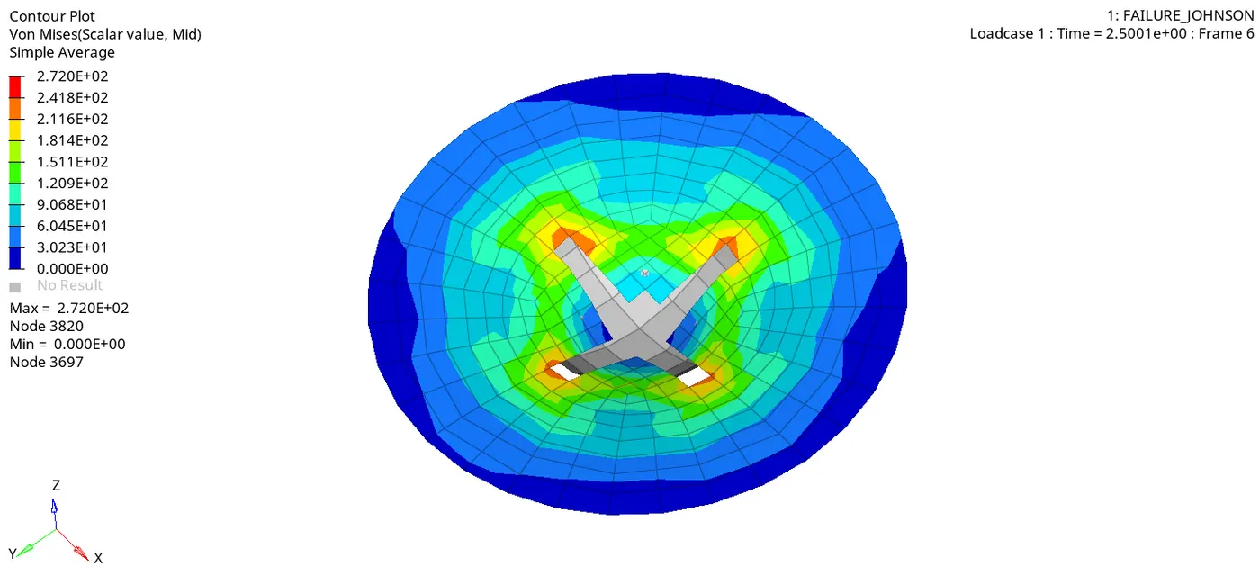
At one integration point the plate fails when the strain reaches EPS_f and a slight brittle behaviour is seen in the simulation before failure.
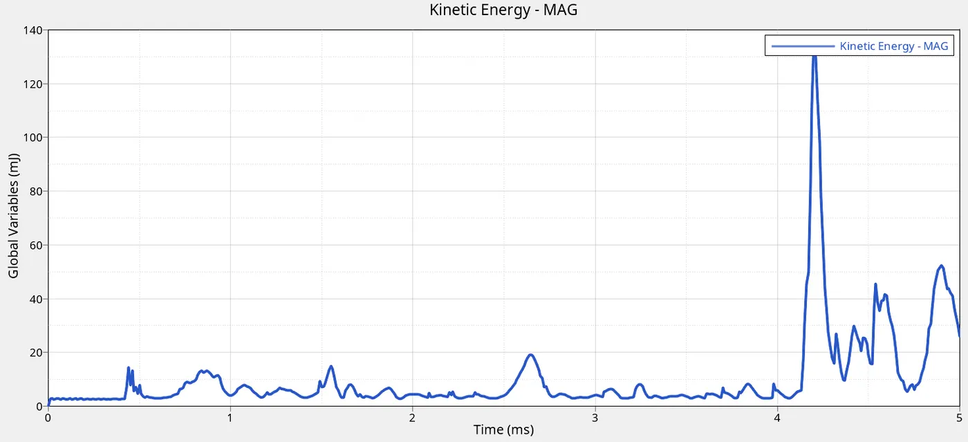
Kinetic energy spiky curves indicate the gradua
l element deletion when the the 0.151 plastic strain is reached
CASE_7
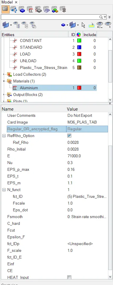
This material card is an isotropic elasto-plastic material using user defined function for work-hardening portion of stress strain curve.
MATERIAL CARD : LAW_36
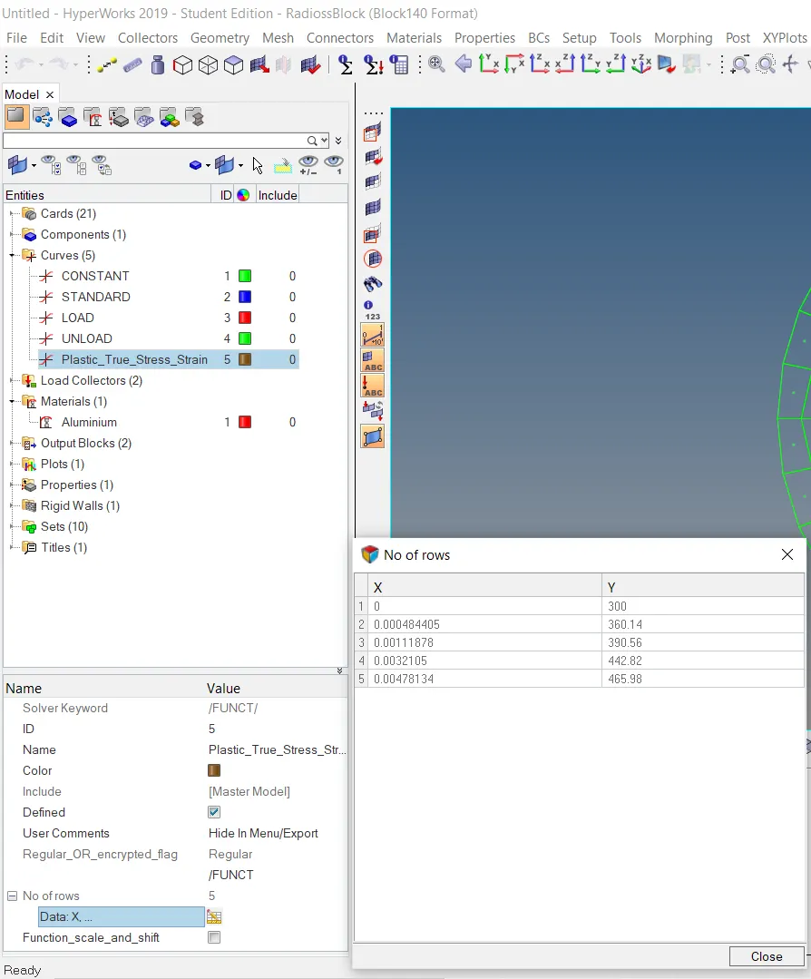
Below it can be seen that a custom the stress-strain curve (Plastic_True_Stress_Strain) was computed for this law to be simulated.
|
Time of simulation |
01:29 |
| Total number cycle |
51660 |
| Mass error |
0.00 |
| Energy error |
0.9% |
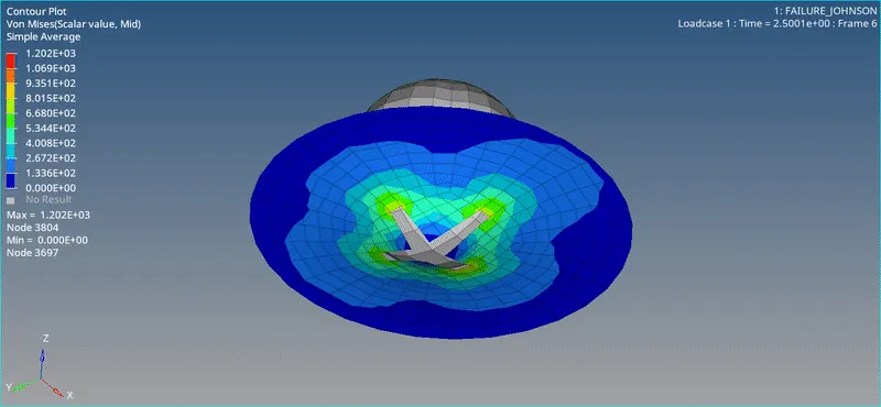
Stress values ar very large this is due to the custon function curve and the eps_max value
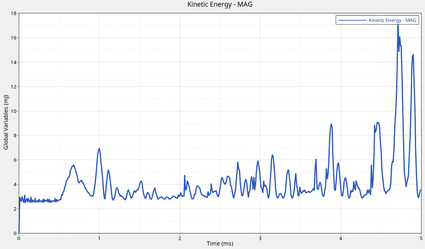
Kinetic energy spiky curves indicate the gradual element deletion when the the 0.16 plastic strain is reached
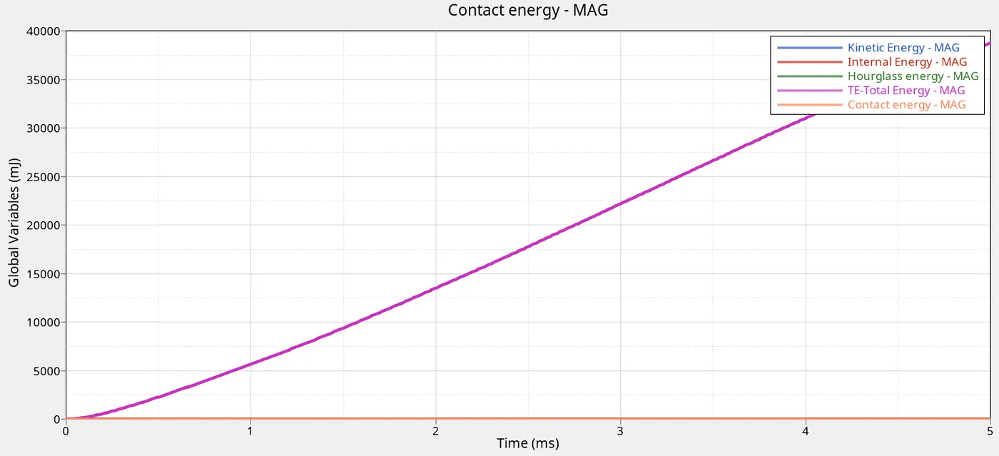
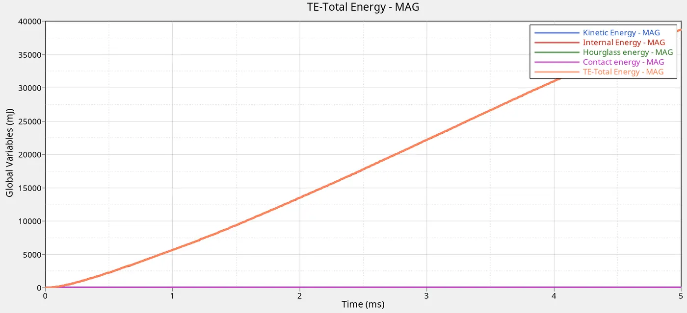
The internal energy is increasing linearly as the ball crushes the plate. So is the total energy. The hourglass and contact energy remains constant at 0 due to its high physical stability
CONCLUSION
Per the simulation made ,the best case on field scenario depends on the situation.
Law_1 is good for elastic material
Law_27 is good for brittle material
Law_2 with Xfem formulation is accurate for ductile materials. The case_2 in this case is more suitable for realistic scenario because of the crack formulation