SIMULATION OF A BEAM CRUSHING ON A RIGID WALL WITH DIFFERENT SHELL PROPERTIES
OBJECTIVE : The aim is to compare the base simulation results of a crush beam on a rigid wall with a simulation with a modified shell properties.
MODEL : The model beam is connected with a base rail via springs and spot weld. A mass is atttached to the right end of the beam on a rigid link which rovides the force needed to crush the beam against a rigid wall. There are going to be two different simulations run in this task. Case 1 is going to be made without specifying any shell element properties and vice versa for Case 2. Recommended shell properties for case two is below:
Recommended properties:
| Parameters | Comment | |
|
Ishell =24 |
QEPH 4 nodes shells are best combination of cost and accuracy. | |
|
Ismstr=2 |
Full geometric nonlinearities (default)with possible small strain formulation activation in RADIOSS Engine. | |
|
Ish3n=2 |
Standard 3 noded shell (C0)with modification for large rotation(default) |
|
| N=5 | Number of integration points set to 5 for accuracy bending. | |
|
Ithick=1 |
Thickness change is taken into account for accuracy. |
|
|
Iplas=1 |
Iterative plasticity for good accuracy. |
Both results are compared by graphing their total energies, hour glass energy , contact energy internal , von misses and kinetic energy.
CASE_1
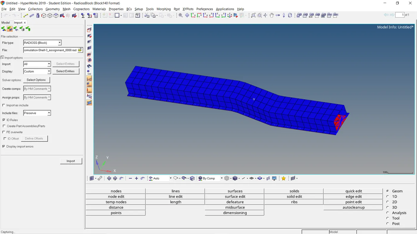
The satrter and engine files are given and both placed in a common folder in the primary hard disk directory. Using radioss, the starte file is imported with solver deck.
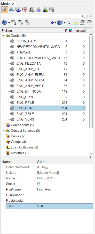
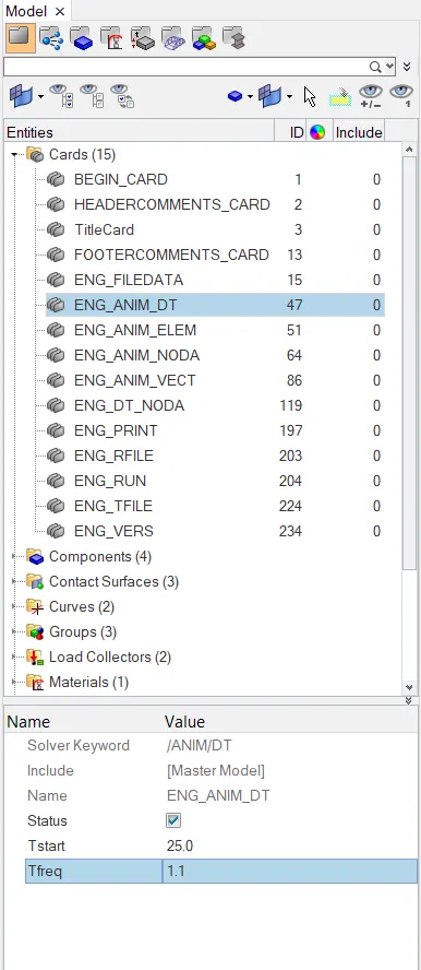
For Both cases , the animation step is set between 25 and 60. The termination time step is set at 55ms. Considering animation step of 55, Tfeq = termination time /Animation step is calcuilated as 1.1
These numbers are changed in the card properties
All the shell formulation properties was left unchanged and the simulation was run using the analysis tab. - nt 4 was specified at the options panel to control the number of CPU's being used by Radioss.
The simulation file "hd3" is opened using hyperview and the results are analysed
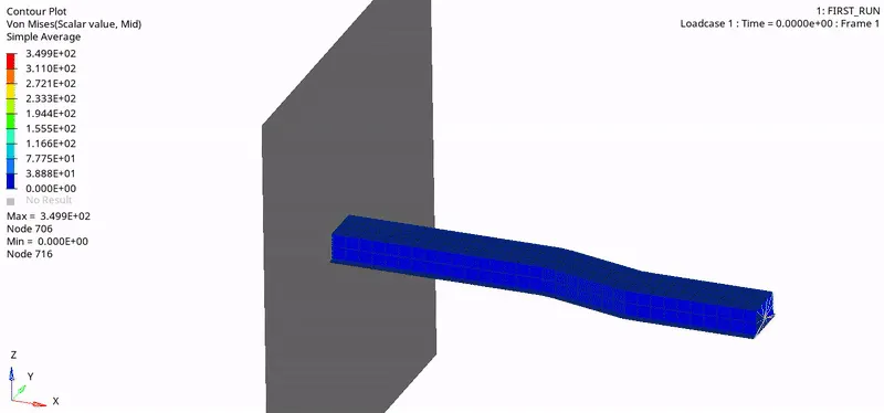
Maximum von - Misses = 3.499E+02 N/mm^2
Maximum plastic Strain = 5.572E-01
Maximum hourglass energy = 1.301E+04
ENERGY AND MASS ERROR
The enrgy and mass error needs to be checked to see if they are withen the tolerable range. Using the energy file (0001) .The criteriqa is examamined with notepad editer.
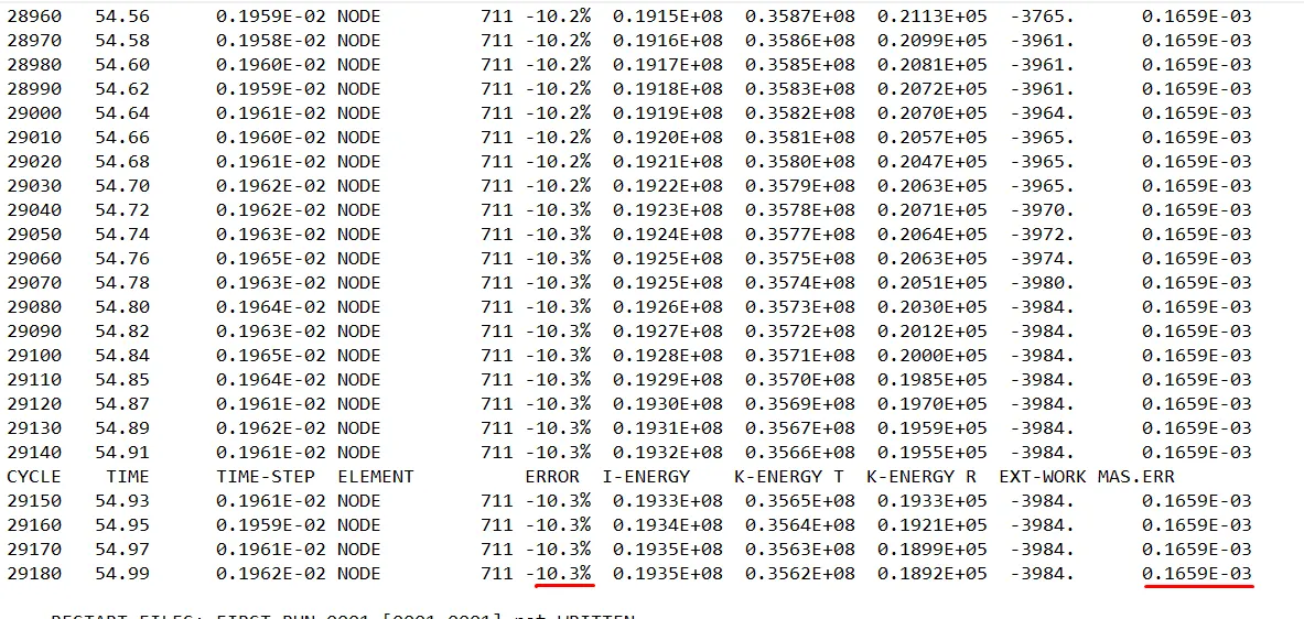
The energy error is well lesser than -15% and the mass error is 0.1659E-03
Using Hypergraph, the "t01" file is imported to examine the graphical behavior of certain global variables.
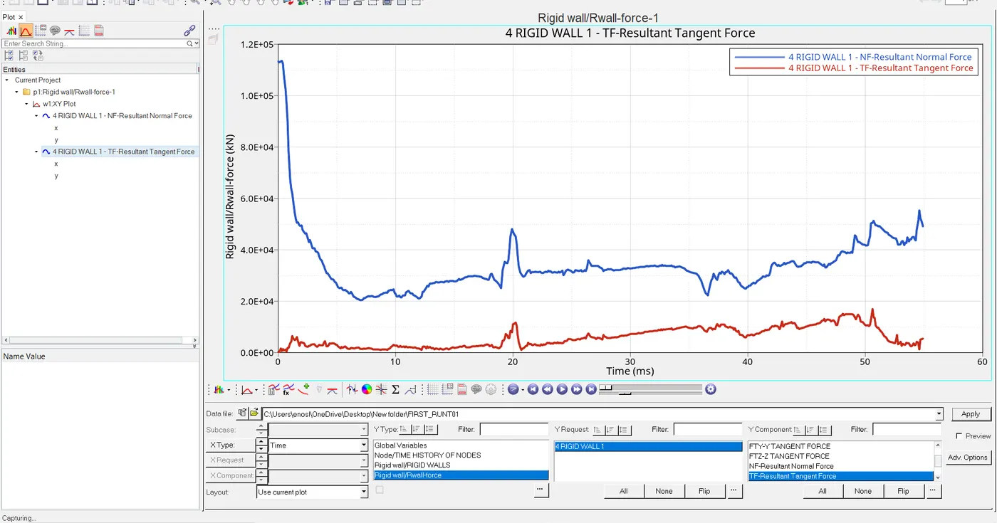
Using Rigid wall analysis the normal force and tangential force is plotted. It can be seen that the normal force at the beginning was very high nd began to drop with time . This shows how the force started of high and later reduced due to frictional forces developed during the crush. Therefore the tangential force shows the evidence of increase where there is decrease in normal force.
Below is a graph of certain global variable variation with Time
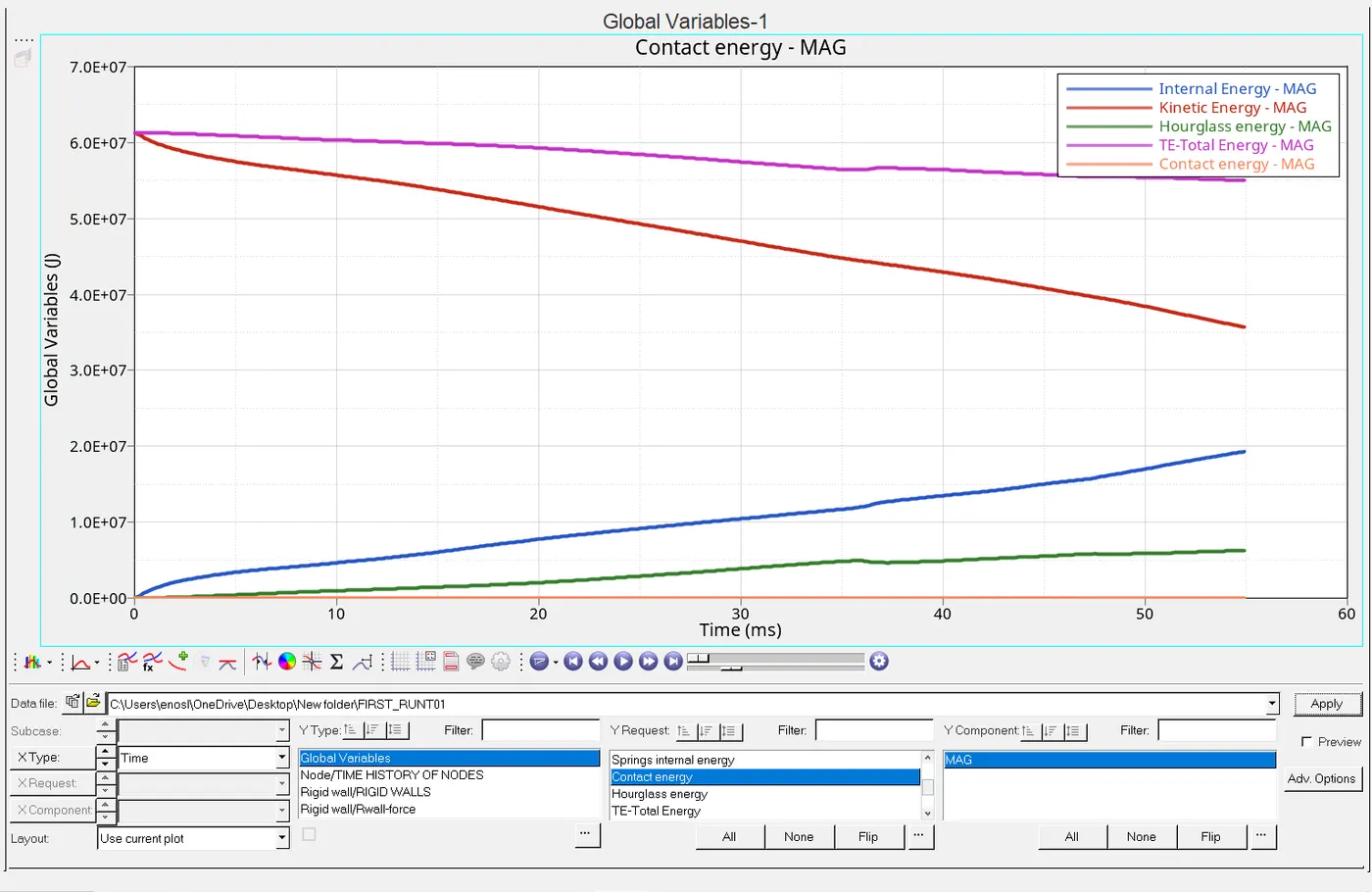
The internal energy is increasing with time because work is done on the beam causing an increase in its internal energy.
The kinetic energy is decreasing with time due t the fact that the initial kinetic energy applied is not conserved but being transferred to sound etc as the beam deforms and does not return to its original shape( inelastic collision). initial kinetic energy becomes greater than the final.
The hourglass energy is increasing with time.
Contact energy remains constant
It can be seen that energy is absobed as deformation occurs via decrease in total energy decrease
CASE_2
THESE SHELL FORMULATION PROPERERTIES ARE EDITED BEFORE SIMULATION IS RUN
Recommended properties:
| Parameters | Comment | |
|
Ishell =24 |
QEPH 4 nodes shells are best combination of cost and accuracy. | |
|
Ismstr=2 |
Full geometric nonlinearities (default)with possible small strain formulation activation in RADIOSS Engine. | |
|
Ish3n=2 |
Standard 3 noded shell (C0)with modification for large rotation(default) |
|
| N=5 | Number of integration points set to 5 for accuracy bending. | |
|
Ithick=1 |
Thickness change is taken into account for accuracy. |
|
|
Iplas=1 |
Iterative plasticity for good accuracy. |
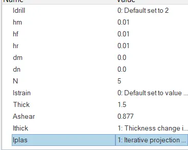
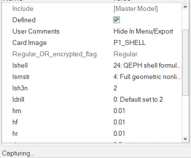
Simulation was run juust like in case 1 and the results which is very much different from case_1 can be seen below
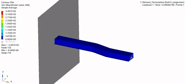
aximum von - Misses = 3.491E+02 N/mm^2
Maximum plastic Strain = 6.386E-01
Maximum hourglass energy = 0
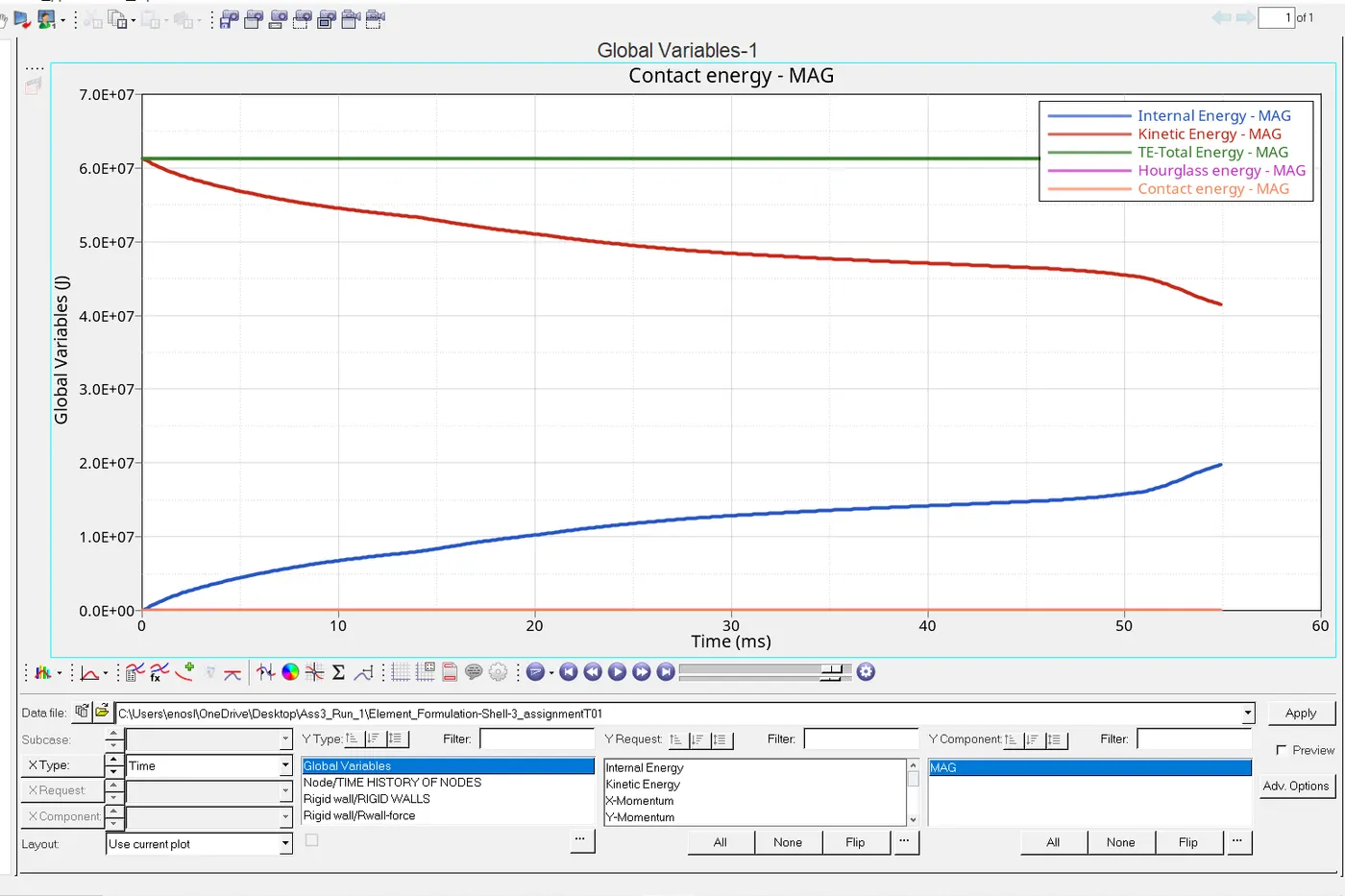
The hourglass energy has reduced to zero due to the application QEPH reduced integration method. The animation has shown a more realistic representation of the deformation due to the introduction of the changed properties.
ENERGY AND MASS ERROR
The enrgy and mass error needs to be checked to see if they are withen the tolerable range. Using the energy file (0001) .The criteriqa is examamined with notepad editer.
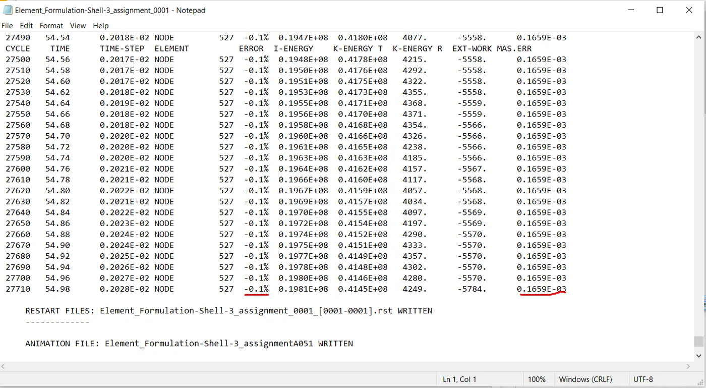
Energy error =-0.1
mass error = 0.1659E-03
It can be seen that the energy error has reduced more compared to case_1's -10%. The mass error rmained the same .
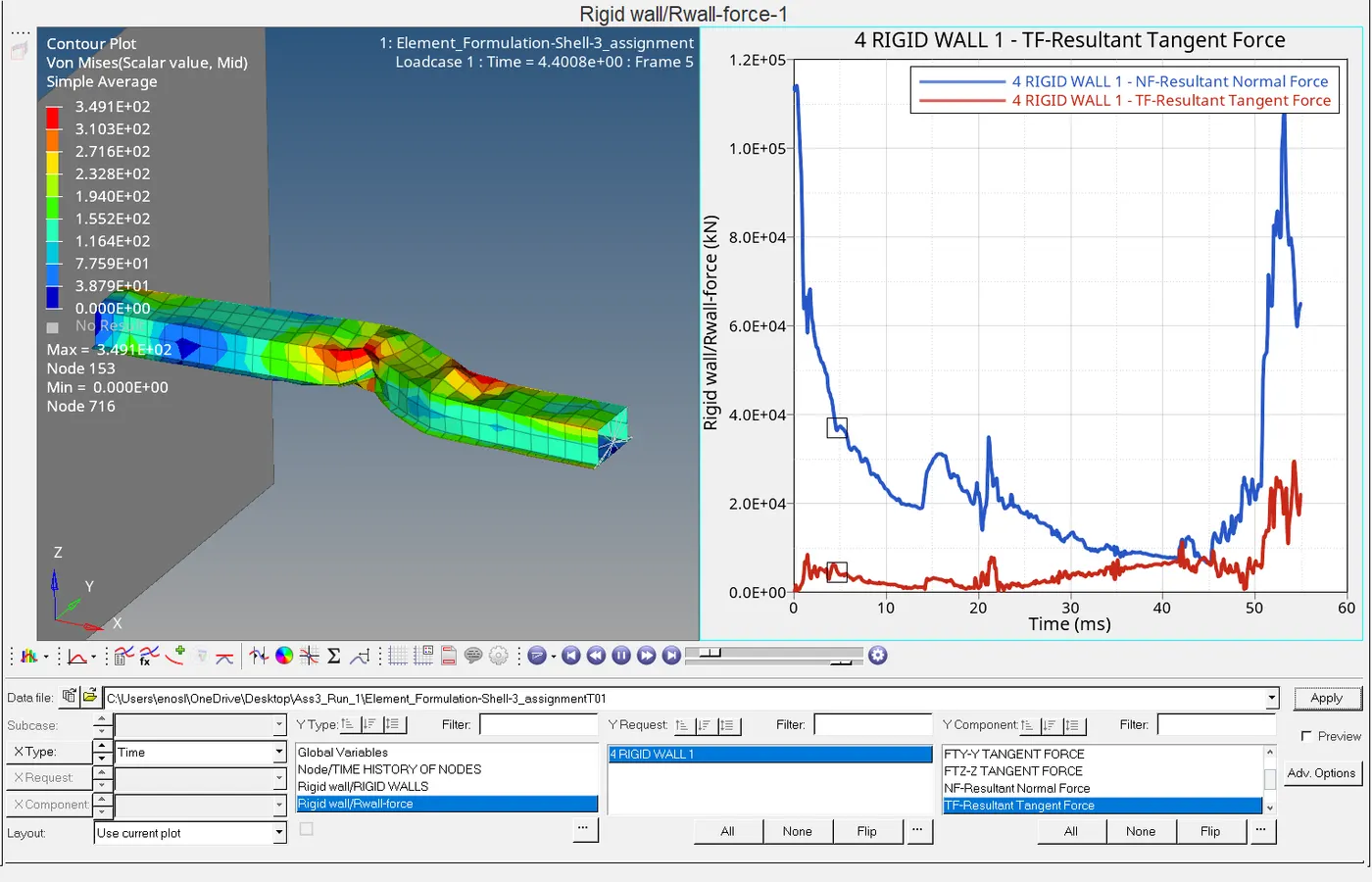
It can be seen that the normal force is different from the case _1 . Towards right end of the graph normal force increases due to the change in deformation of the beam.
Below is the representation of the global variables
RESULTS AND CONCLUSION
|
VARIABLE |
CASE 1 |
CASE 2 |
|
HOURGLASS ENERGY |
Hourglass error was quite significant here with an increase linearly with time |
Hourglass error was eliminated, and this was constant trough time |
|
TOTAL ENERGY |
Energy error was -10 and the energy was seen decreasing. |
Energy error was 0 and energy was conserved and constant |
|
KINETIC ENERGY |
Kinetic energy was not conserved but decreasing |
Kinetic energy was not conserved but decreasing also but the final value little higher than case 1 |
|
INTERNAL ENERGY |
Internal energy increased in the system as work was impacted on the beam |
Internal energy increased in the system as work was impacted on the beam |
|
CONTACT ENERGY |
Contact energy remained constant |
Same |
CONCLUSION
Due to the QEPH specification , hourglass error was stabilized and the deformation and plastic strain was seen in a more realistic way by specifying full geometric nonlinearity and allowing thickness change to be considered . Case 2 showed better beam crush results