Creation of 1D Connectors
OBJECTIVE:-To create 1D connectors on a given model with given quality criteria by using hyper works.
CAD MODEL IMAGES:-
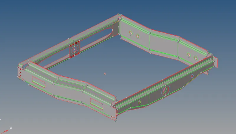
PROCEDURE:-
1.Import the file into hypermesh -select→import→import geometry.
2.Click on the files select STP file and click on import
3.It shows on graphical area
4.Goto tab bar click on components. In this 9 components are there as shown In the figure.
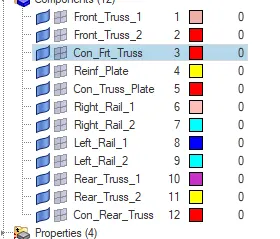
5.Select one component surface other components will hide the surfaces.
6.Set the given quality criteria into a criteria file.
7.Next goto 2D click on the auto mesh as shown in fig.


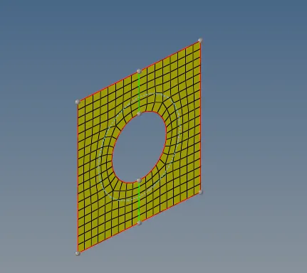
8.By using this tool creating the mesh as shown in fig.
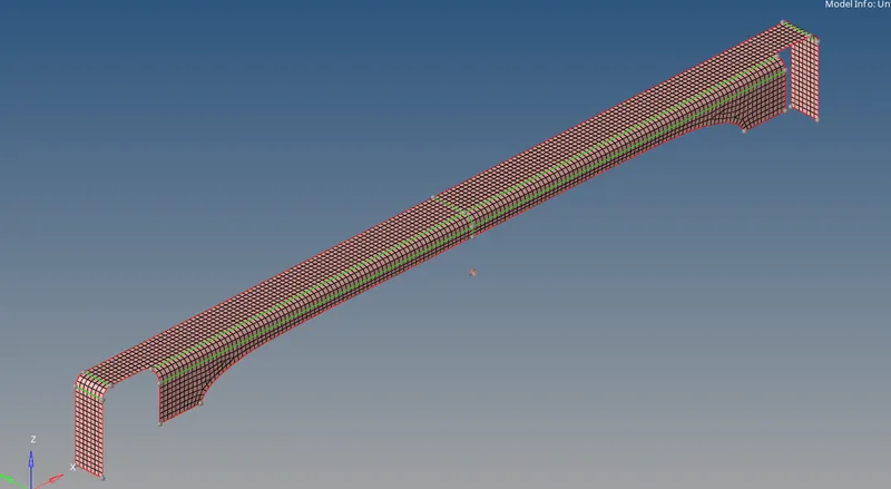
9.Repeat the above steps for all components as shown in fig.
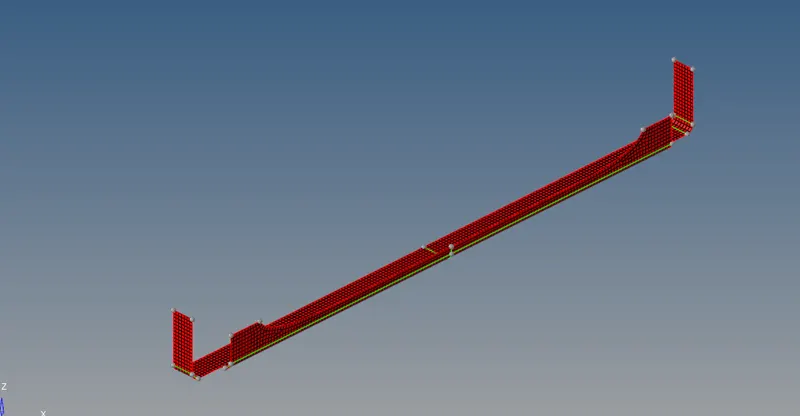
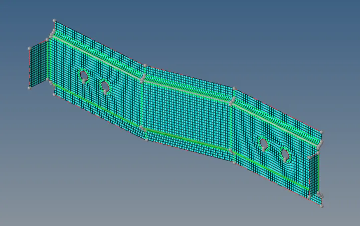
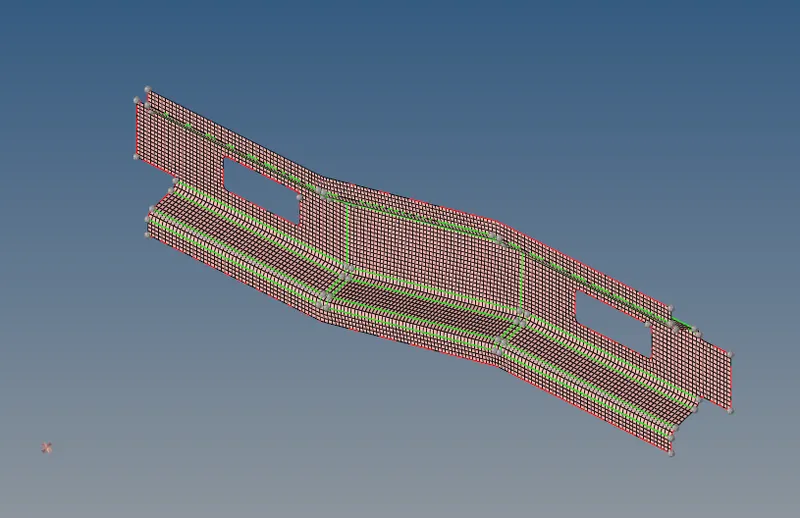
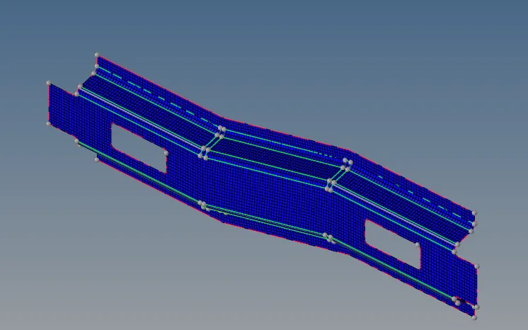
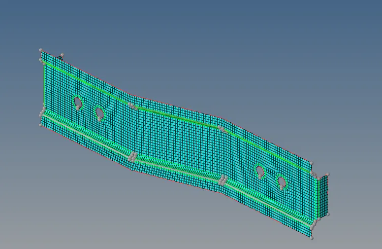
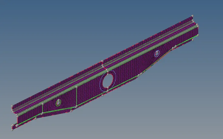
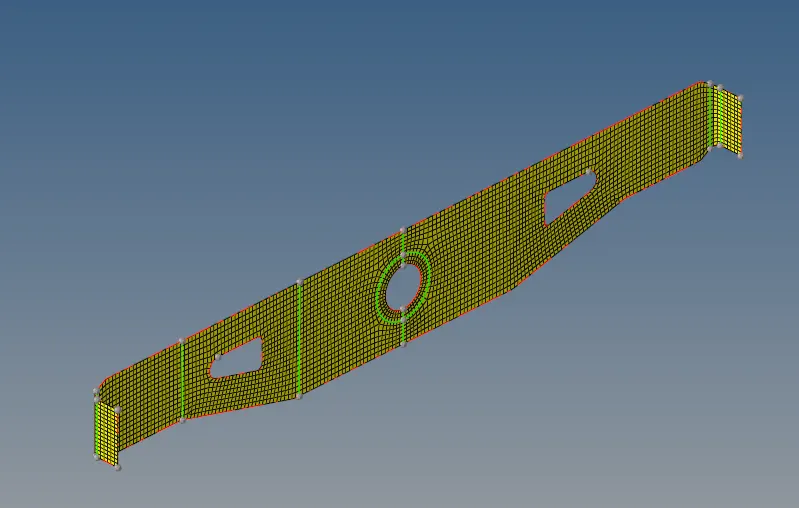
10.Next goto 1D click on the connectors select seam as shown in fig.


11.Right_Rail_2 & Front_truss_1:- Seam-Quad(angled+capped+L) connector will be created as shown in figure below.

12 On the surfaces right rail2 and front truss1 other surfaces will be hidden.
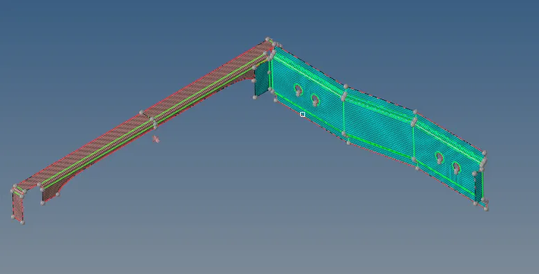
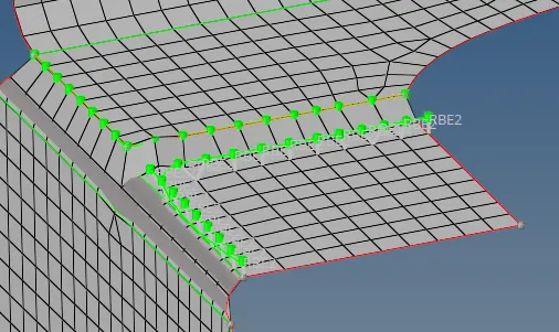
13.Left_Rail_2 & Front_truss_1:- Quad elements created as shown in figure.
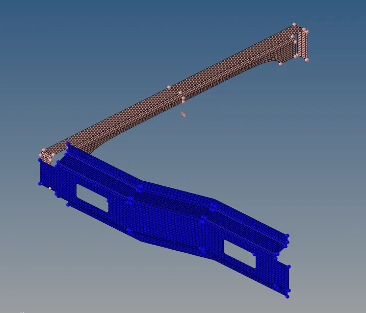

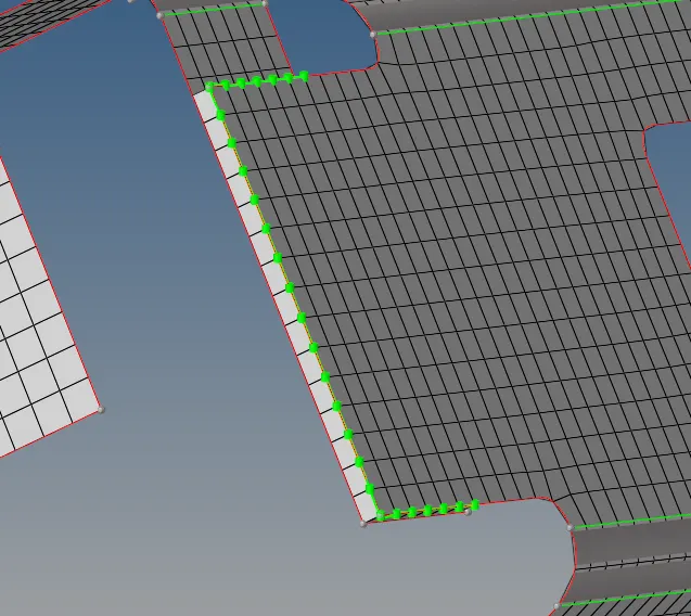
14. Front_truss_2, Front_truss_1 & Right_Rail_1:- Spot weld with 2 Layers and 5 mm Diameter created
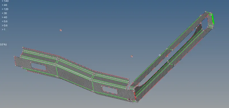


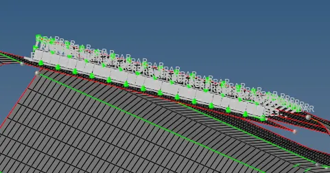
15. Front_truss_2, Front_truss_1 & Left_Rail_1:- Hexa (Adhesive)
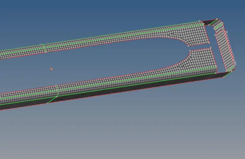

16.Rear_truss_2 & Right_Rail_2:- Bolt Connector
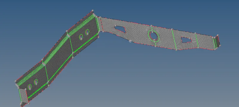


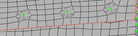
17.Rear_truss_2 & Left_Rail_2:- Bolt Connector repete the above steps for rear truss2 and left rail2.
18.Right_Rail_1 & Right_Rail_2:- Spot-weld with Rigid Elements created as shown in below.

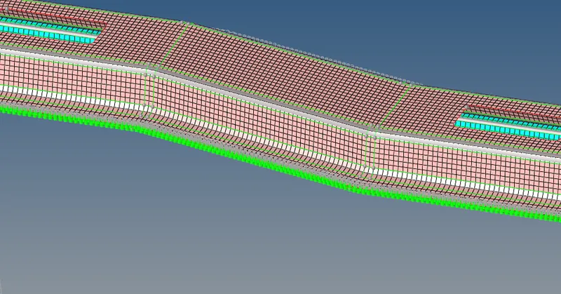
19. Left_Rail_1 & Left_Rail_2:- Spot-weld with Spring Elements created

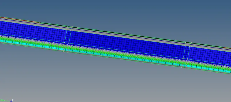
20.By using the above steps all components are joined with a suitable connectors
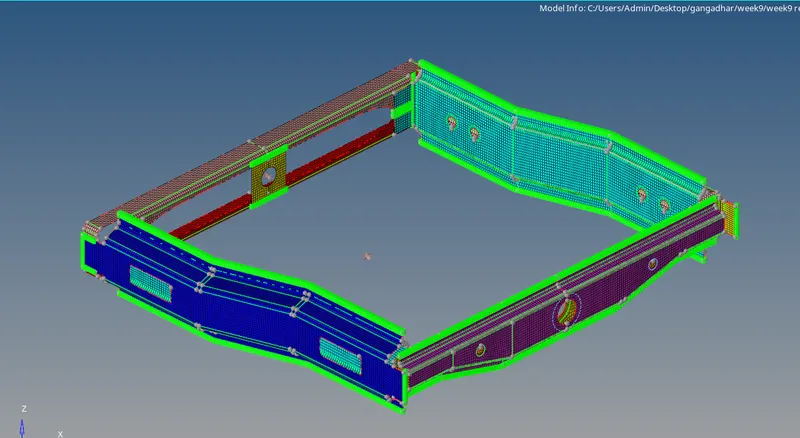
RESULT:-successfully completed creating 1D connectors by using hyper works