Bird Strike - Project - 2
AIM:-
To simulate the non-linear transient bird strike where the bird enters to hit the turbine blade by using LS-Dyna.
INTRODUCTION:-
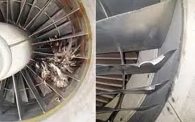
- Bird strikes pose a significant threat to aircraft structures, as contact with a bird while in flight can cause significant structural damage.
- For more than 30 years, computational approaches have been used to design birdproof structures, and they have proven to be a cost-effective alternative to costly physical certification testing with live birds.
- The bird behaves as a soft body and flows over the target structure in a fluidlike way at the velocities of interest, with the high deformations of the spreading material being a substantial problem for finite element simulations.
PROCEDURE:-
1. Import the keyword file in LS-Dyna.
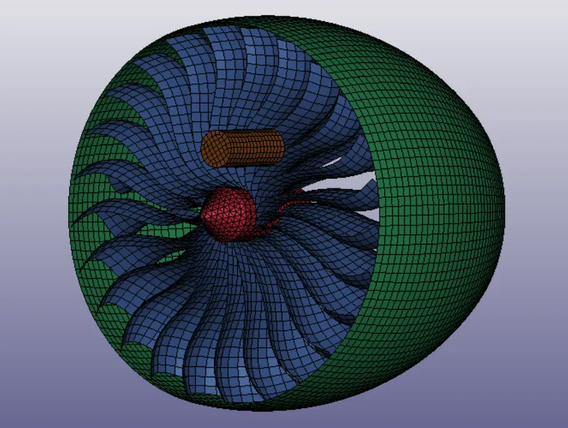
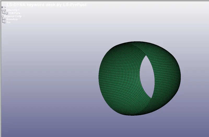
2. It consists of 4 components there are as shown below
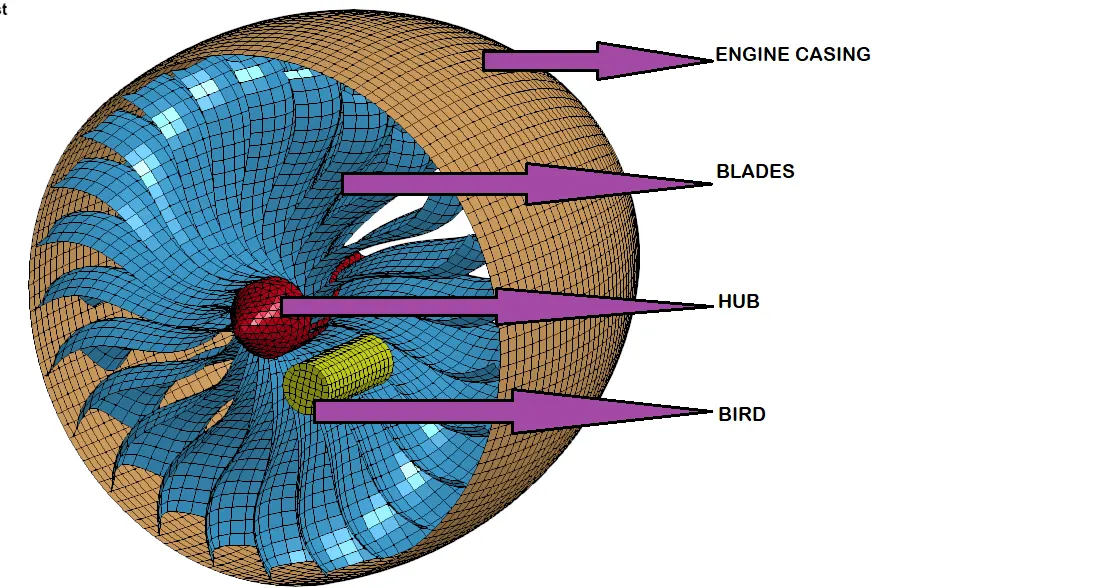
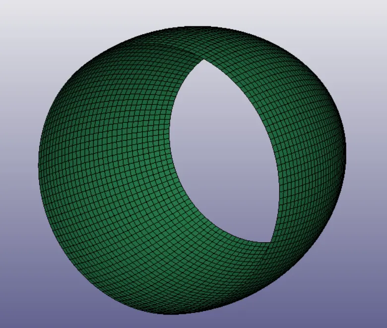
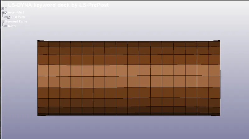
ENGINE CASING
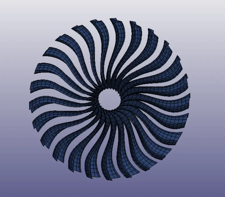
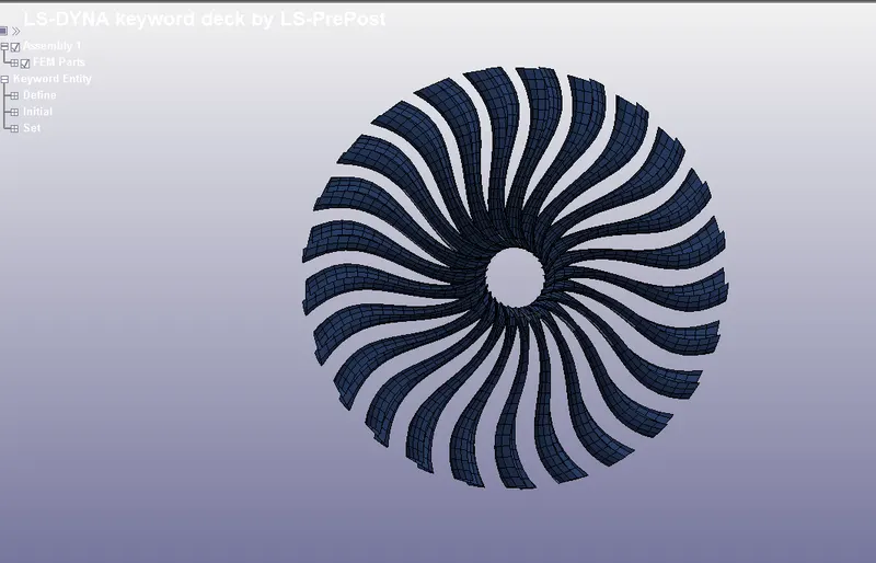
BLADE
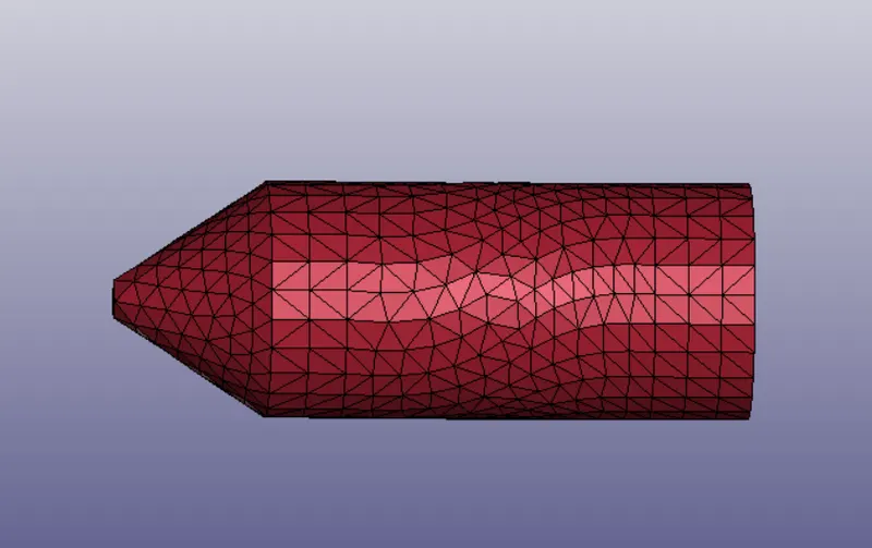
HUB
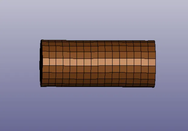
BIRD
3. Create new keyword files for each component as shown below.
Engine Casing
Blade
Hub
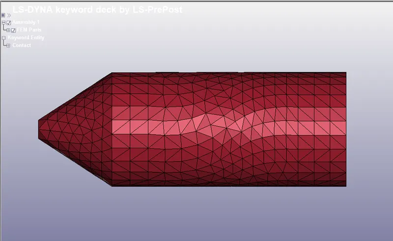
Bird
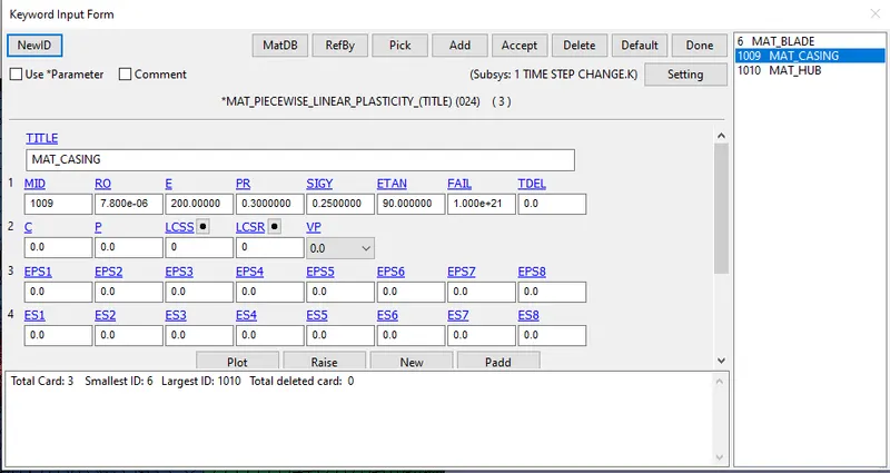
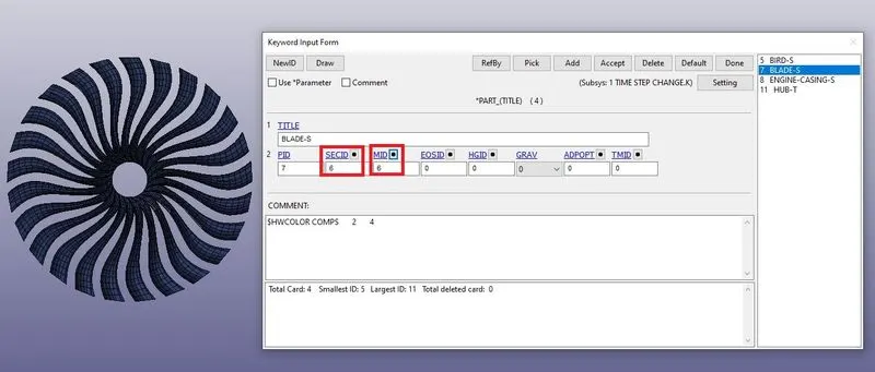
4. Create the material and section for each component as shown below.
Engine casing
Material
Section
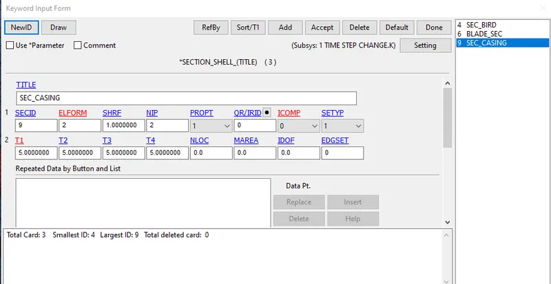
Assign the material and section to the engine casing as shown below.
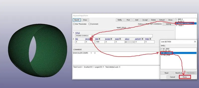
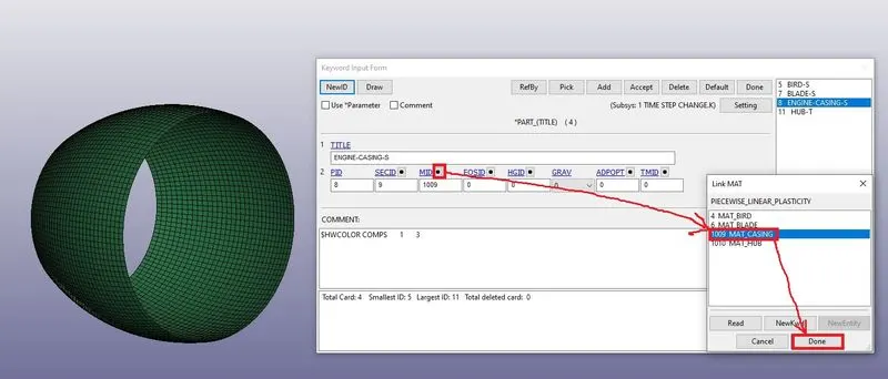
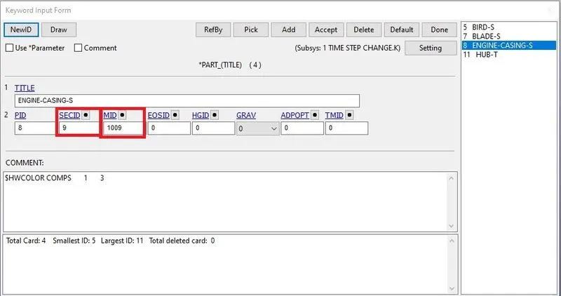
Blade
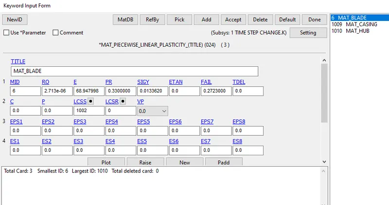
Material
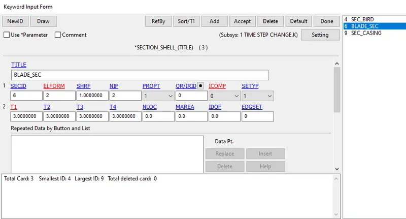
Section
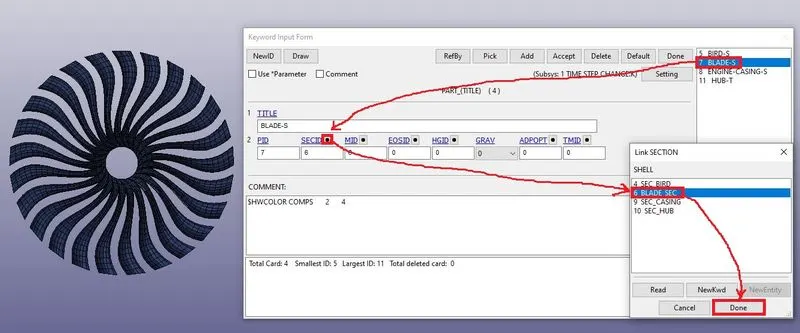
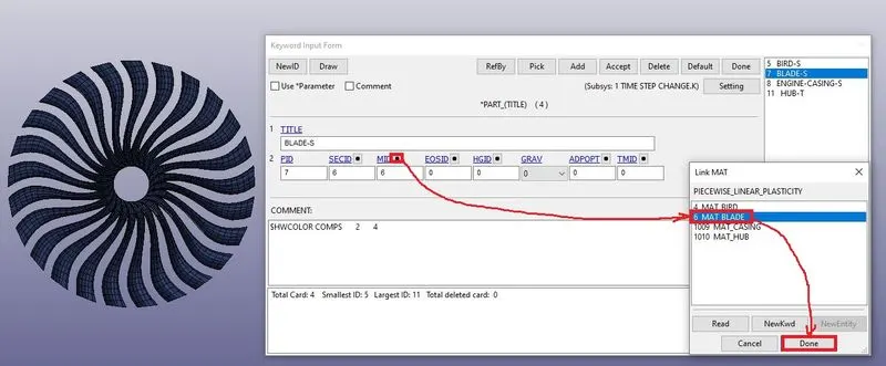
Assign the material and section to the blade as shown below.
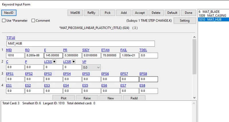
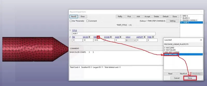
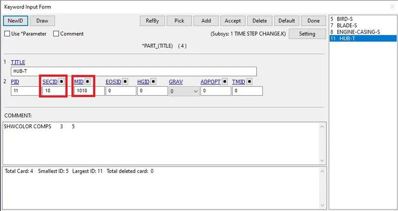
Hub
Material
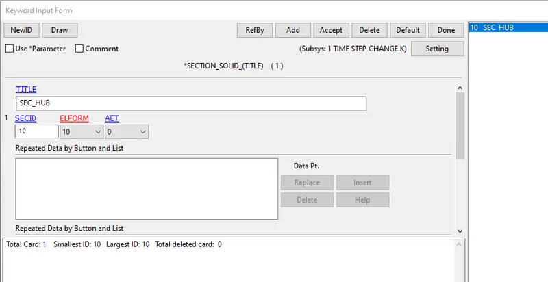
Section
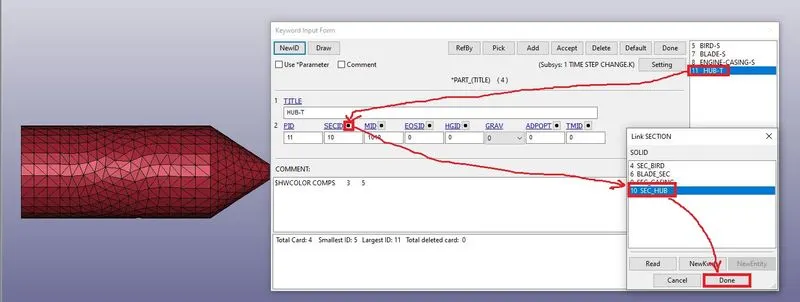
Assign the material and section to the hub as shown below.
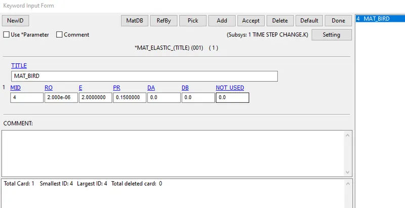
Bird
Material
Section
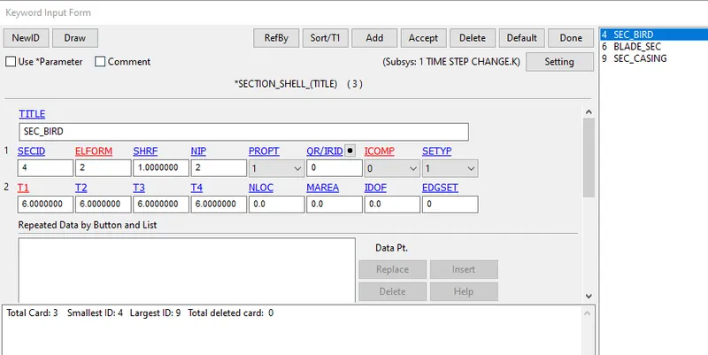
Assign the material and section to the bird as shown below.
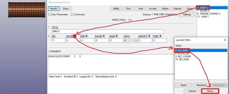
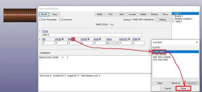
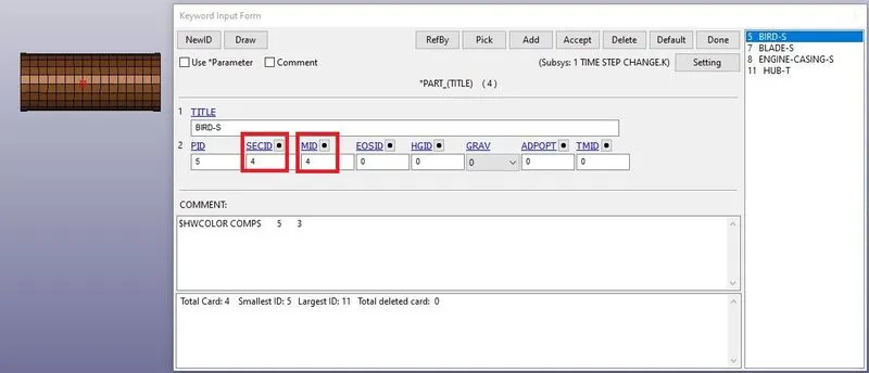
5. Save all components keyword files separately and include all keyword files in one file as shown below.
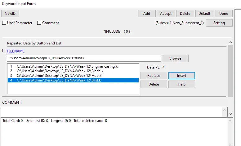
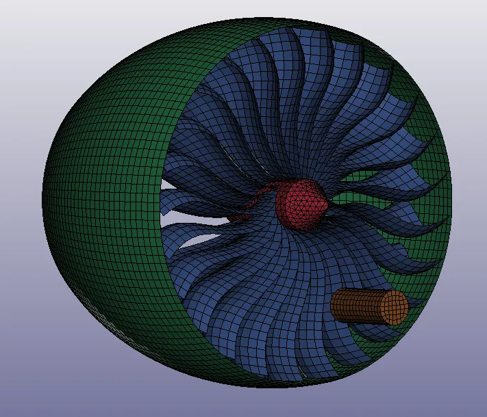
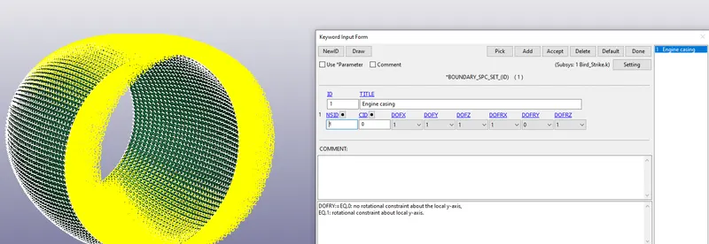
6. next create the boundary condition to the engine casing as shown below.
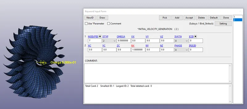
7. Next create the initial velocity for the blade as shown below.
We will assign the Initial velocity generation of Omega(w)= 0.5 rad/ms.
Assume the speed of the blade is nearly 5000rpm then
`(2*pi*N)/60=(2*pi*5000)/60` = 523 rad/s = 0.523 rad/ms = 0.5 rad/ms.
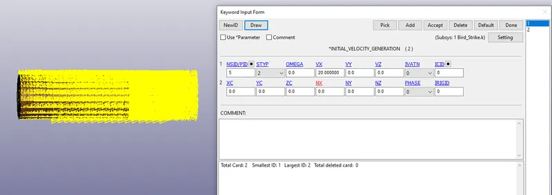
8. Next create the initial velocity to the bird as shown below.
Assign the Initial velocity Generation of 20 mm/ms(72 kmph) in the X-direction
9. Next create the contacts as shown below.
a. Contact between Hub and Blade
A Tied node to surface contact is defined between hub and blade as it is an integrated unit and should rotate along with the blade at a similar angular speed. The master is assigned to Hub and the slave to Blades.
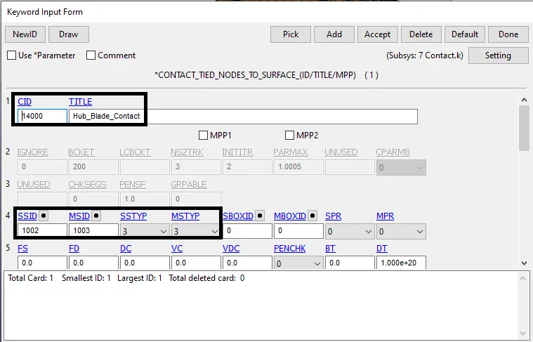
Fig: Contact card defined for the Blade and Hub
b. Contact between Blade and bird
Automatic surface to surface contact is defined between the blade and bird interface with the master node as bird and blade as slave nodes. As we need to observe stress and strain developed in the fan blade, therefore, it is defined as a slave.
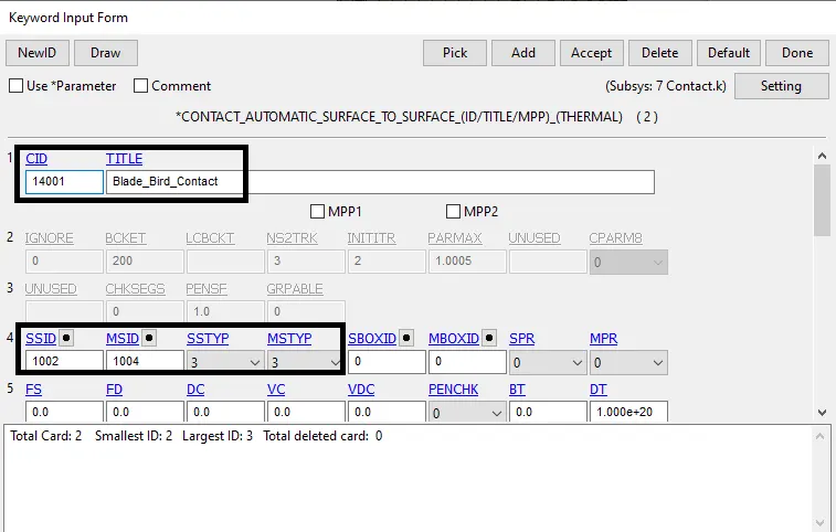
Fig: Contact card defined for the Blade and Bird
c. Contact between blade and casing
Automatic surface to surface contact is defined between the blade and casing interface with the master node as casing and blade as slave nodes.
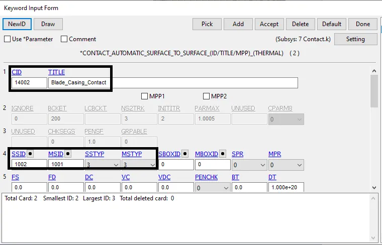
d. Contact for blade ie, self contact
The Automatic single surface contact is defined for the blade self contact. with the master as 0 and slave as the blade.
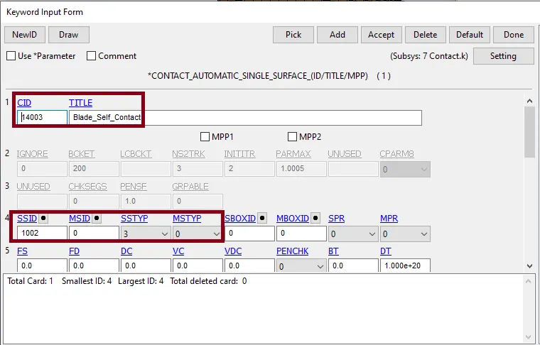
Fig: Contact card defined for the Blade
10. Create the control cards and database cards as shown below.
a. Control cards
Define control cards for Energy, termination, and Timestep as shown below.
Termination time setup is 4 ms and Energy card to take into account hourglass energy with hgen=2 (as shown below)
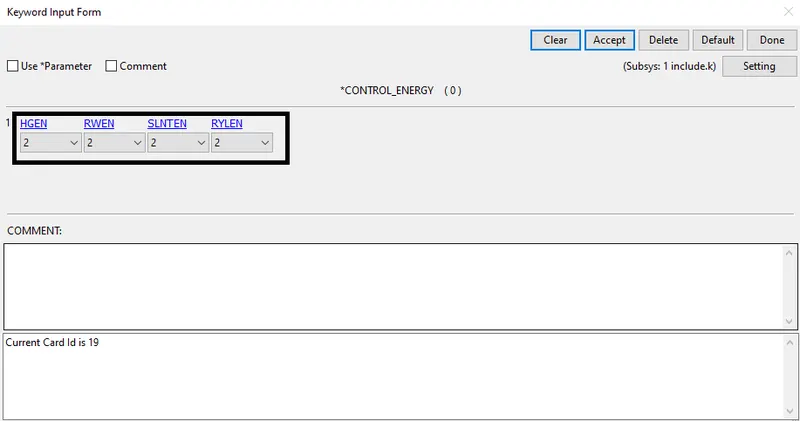
Fig: Control Energy card defined for the simulation
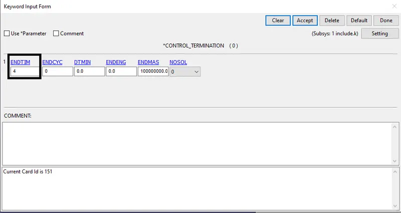
Fig: Control Termination card defined for the simulation
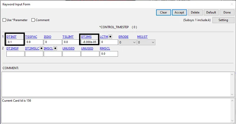
Fig: Control Timestep card defined for the simulation
The Control Timestep card plays an important role in reducing the runtime. we can have a different combination of DT2MS and TSSFAC to check the estimated runtime and % mass added during mass scaling. Here we will try to keep the percentage of mass added below 7% and reduce the runtime.
b. Database Card
Among the Database card, we will include ASCII, D3PLOT, EXTENT_BINARY (for strain data in post-processing)
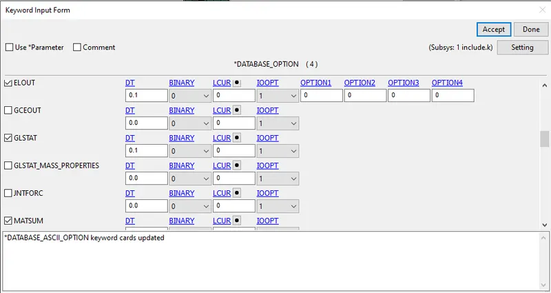
Fig: Database ASCII card defined for the simulation
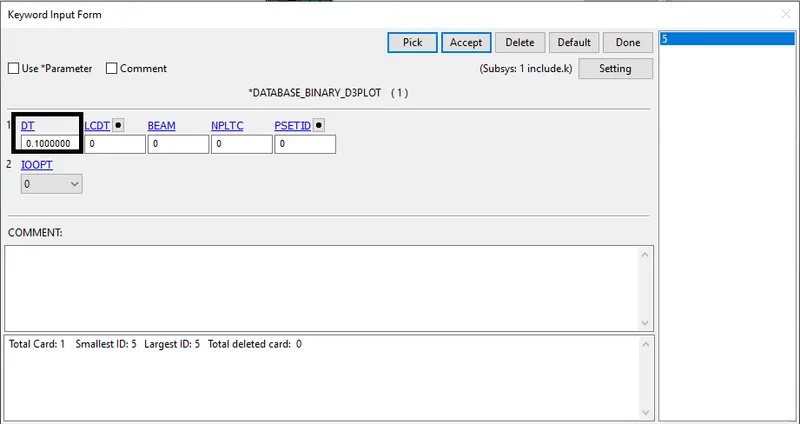
Fig: Database Binary card defined for the simulation
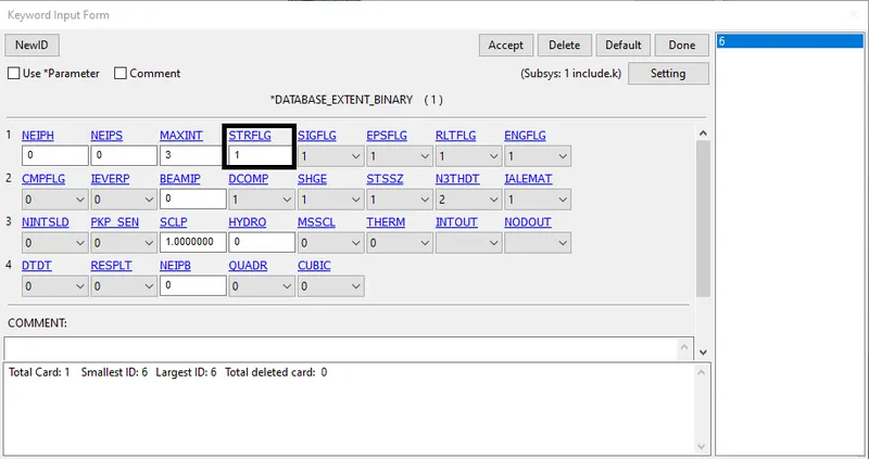
Fig: Database Extent_Binary card defined for the simulation
11. Save the keyword file and run the simulation in Ls-Run.
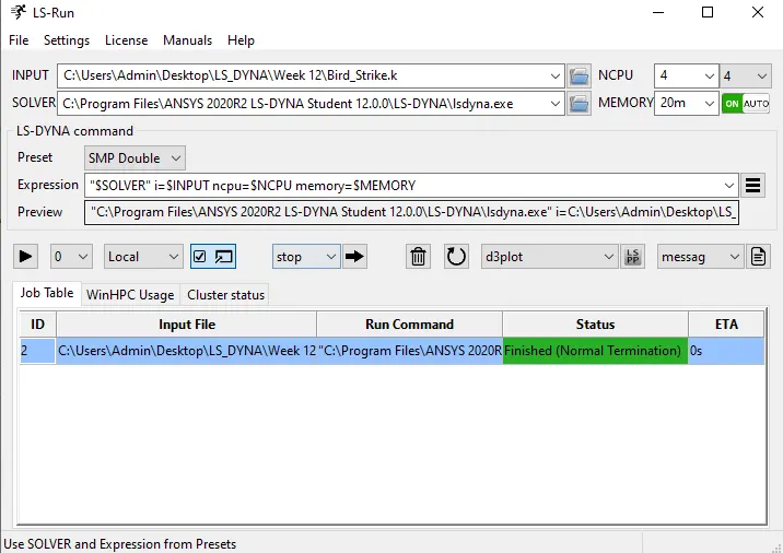
a. In 1st trial, we did this by keeping DT2MS = -6.000E-05 and TSSFAC=0.9 the runtime estimated is 1hrs 11 min but actually, it took 6 min 13 sec with 0% mass addition.
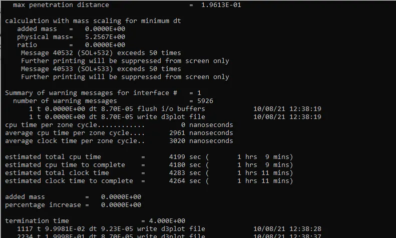
Estimated data before the simulation run
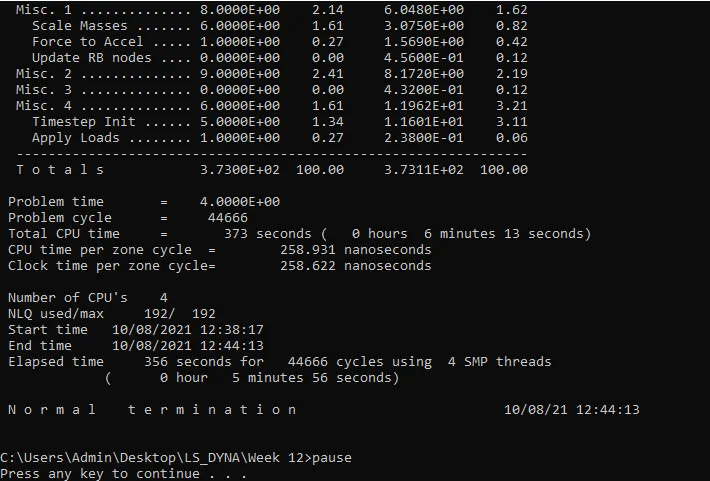
Final data after the simulation run
b. In the 2nd trial, we did this by keeping DT2MS = -6.000E-04 and TSSFAC=0.9 the runtime estimated is 0 hrs 11 min but actually, it took 1 min 21 sec with 2.4% mass addition.
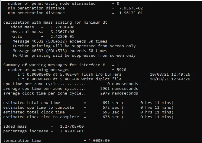
Estimated data before the simulation run
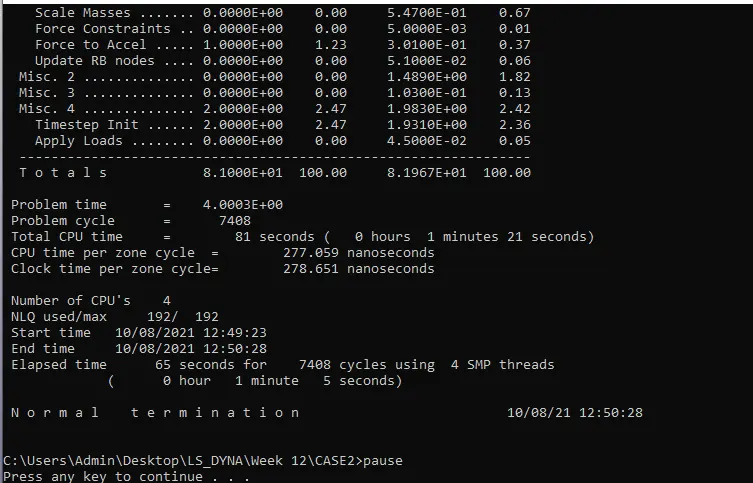
Final data after the simulation run
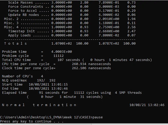
c. In the 3rd trial, we did this by keeping DT2MS = -4.000E-04 and TSSFAC=0.9 the runtime estimated is 0 hrs 16 min but actually, it took 1 min 47 sec with 6.6% mass addition.
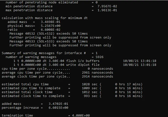
Estimated data before the simulation run
Final data after the simulation run
In the 3rd trial, we got a mass percentage of 7%
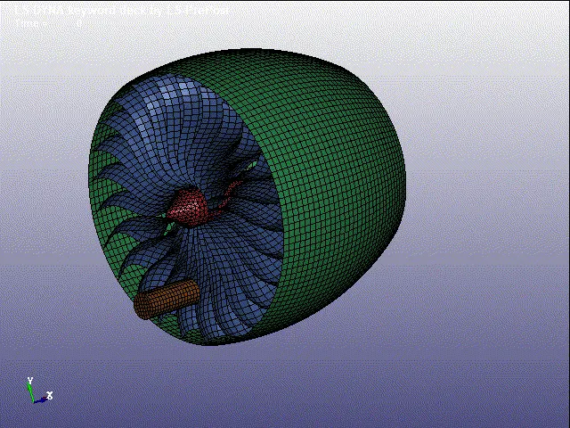
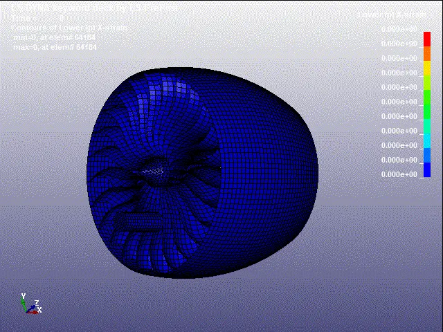
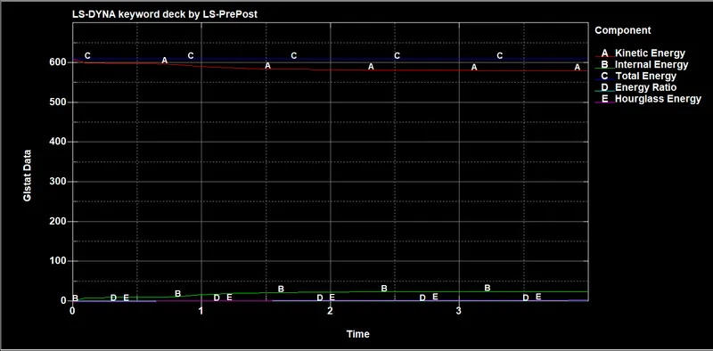
12. Next open the binary plot in LS-pre post and run the animation as shown below.
Stress

Strain
Energy plots
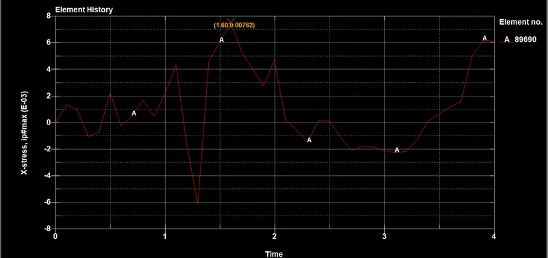
Stress Graphs
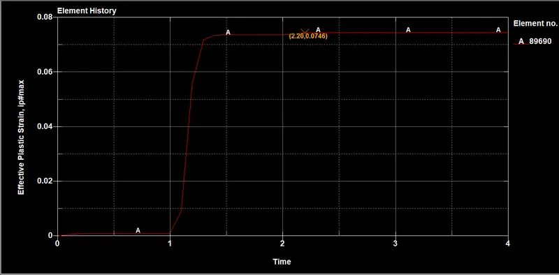
Effective Plastic strain Graph
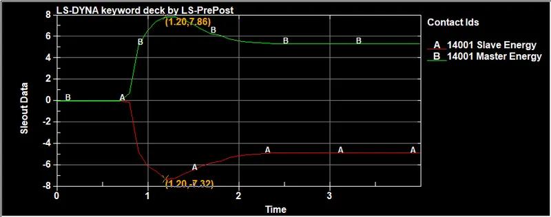
Contact plot (Blade_Bird)
CONCLUSION:-
Finally, The Simple Bird Strike on the Aircraft, Simulation was Carried Out Using LS Dyna And Its results Are Plotted.