Week 3 Sheet metal Bending challenge
1. Objective
To perform sheet metal bending operation for three different cases as mentioned below -
Case 1:Aluminium Alloy 1199( mentioned in the course video), Copper Alloy NL and Magnesium Alloy NL. Find out the Equivalent stress, Equivalent elastic strain and Total Deformation in the Y direction and compare the results for the three materials.
Case 2:With the material as Aluminium Alloy, change the friction coefficient to 0.19 and run the analysis as mentioned in Case 1. Compare the results with that in case 1.
Case 3: Refine the mesh on the plate such that it doesn't cross the academic limit. With Aluminium alloy as material, run the analysis as in Case 1 and compare the results.
2. Case Setup and Execution
The model assembly provided for the assignment consists of three parts - punch, die and plate. The material assigned for the punch and die is structural steel whereas Aluminum Alloy 1199 is used for the plate.
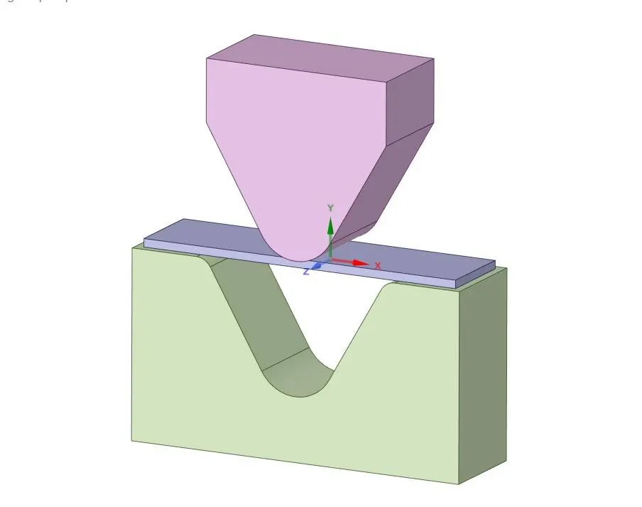
Fig. 1 Model Assembly in ANSYS Spaceclaim
The material properties of the Aluminum Alloy 1199 used for the plate is given in the table below.
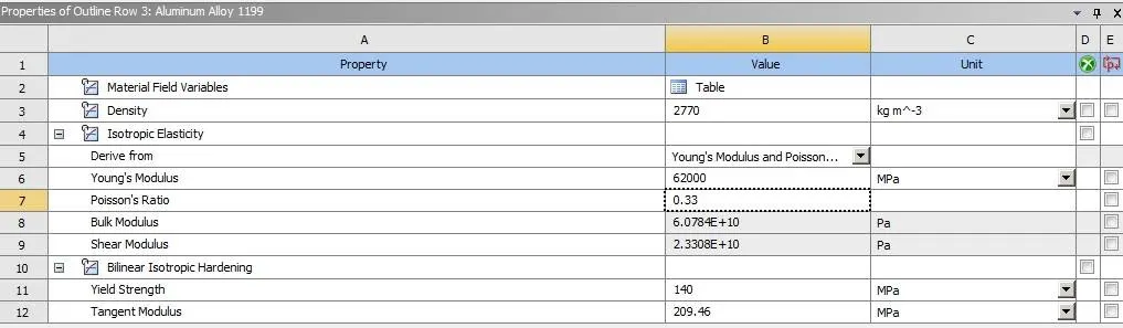
Fig. 2 Aluminum Alloy 1199 Material Properties
A mesh size of 4 mm is used for the punch and die whereas a mesh size of 1 mm is used for the plate. Face Sizing with a mesh size of 1 mm is applied to the faces of the punch and die which will be in contact during analysis. Tetrahedral Meshing is selected in mesh method for the plates exclusively. The number of nodes and elements after meshing are 18082 and 6276 respectively.
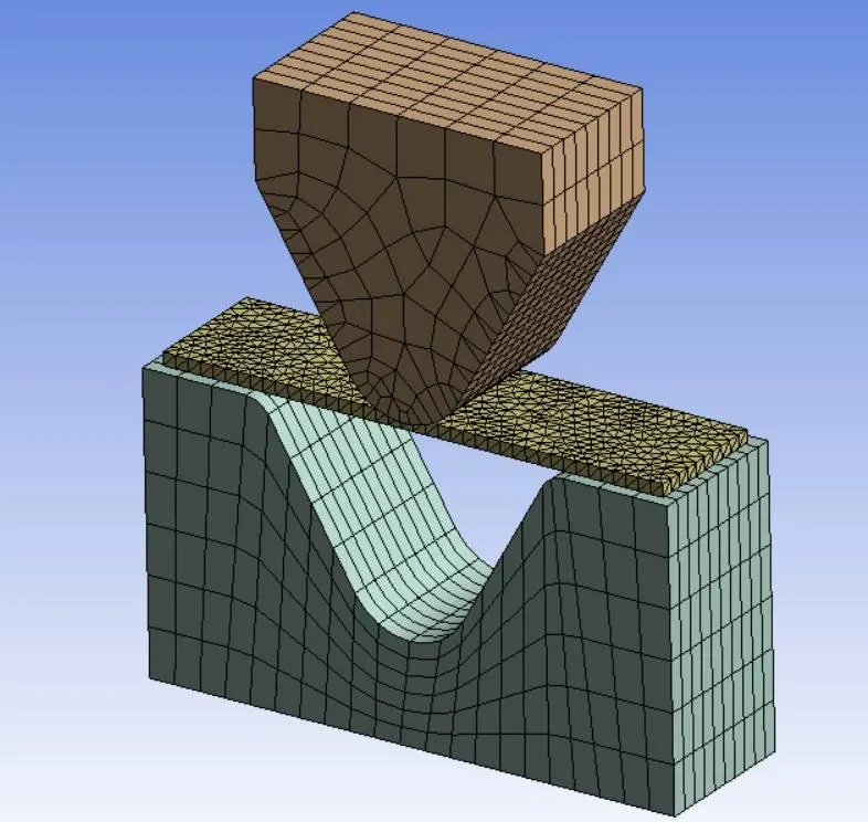
Fig. 3 Meshed Model
2. a Contact Settings
The type of contact assigned to the two mating interfaces - Punch to Sheet and Sheet to Die is frictional as these surfaces will slide when the punh moves in a downward direction after the application of force. The contact settings are shown in the table below.
| Definition | Settings |
| Type | Frictional |
| Friction Coefficient | 0.1 |
| Behaviour | Asymmetric |
| Normal Stiffness Factor | 0.1 |
| Formulation | Augmented Lagrangian |
| Interface Treatment | Add Offset, Ramped Effect |
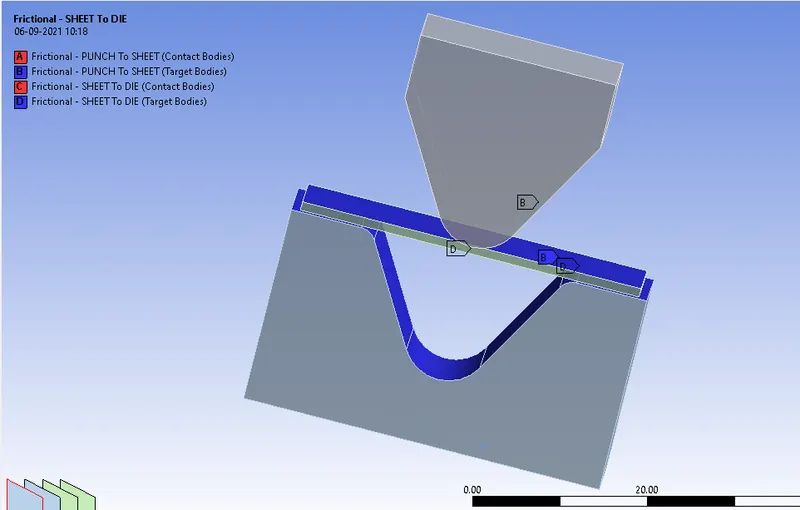
Fig. 4 Contact Definition
2. b Analysis Settings
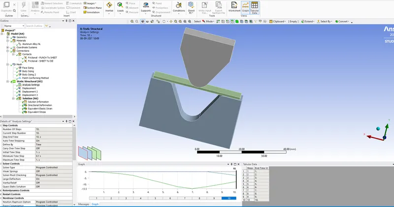
The different values of analysis settings used for this simulation are mentioned in the table below.
| Definition | Settings |
| No of Steps | 10 |
| Stabilization | Constant |
| Energy Dissipation Ratio | 0.1 |
| Large Deflection | On |
| Solver Type | Direct |
2. c Boundary Condition
There are three displacement boundary conditions for the analysis.
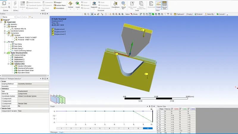 Fig. 5 Displacement Boundary Condition
The displacement is given to the top face of the punch in mm in the negative y-direction in subsequent steps of -1.5,-3,-6,-9,-12-,13.5,-12,-10,-8.
The displacement of the two faces in the Z direction of the sheet is fixed.
A displacement of -1.5 and -3 mm is given to the 5 faces of the die in the negative y-direction so that the die came to retract when the punch is removed.
3. CASE 1 - RESULTS
For CASE-1 analysis three different materials are assigned to the plates, i.e, Aluminium Alloy 1199, Copper Alloy NL, Magnesium Alloy NL while structural steel is used for the punch and die.
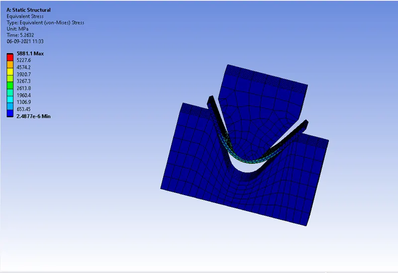
Fig. 6 Equivalent Stress - Aluminium 1199
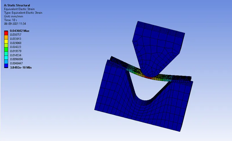
Fig. 7 Equivalent Strain - Aluminium 1199
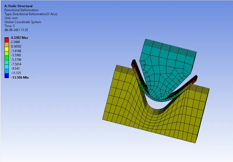
Fig. 8 Directional Deformation (Y Direction) - Aluminium 1199
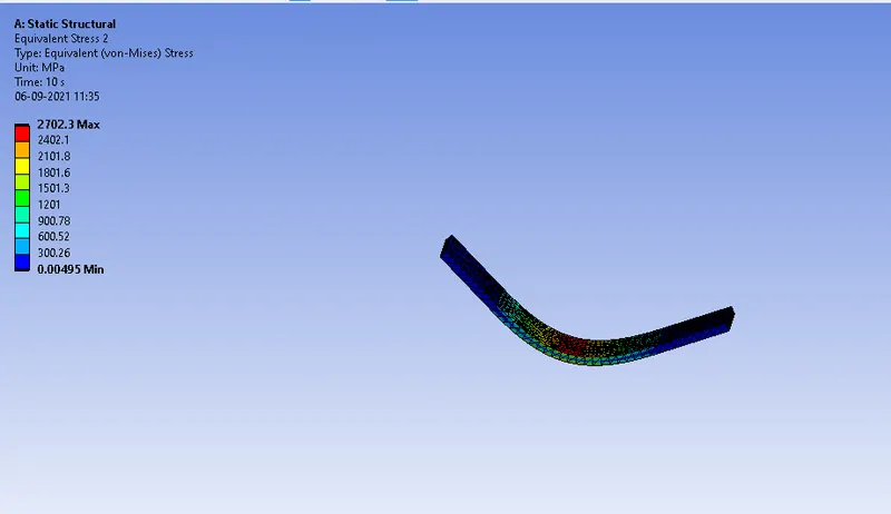
Fig. 9 Equivalent Stress in Sheet - Aluminium 1199
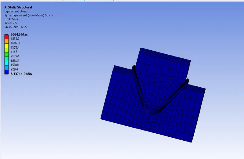
Fig. 10 Equivalent Stress - Copper Alloy
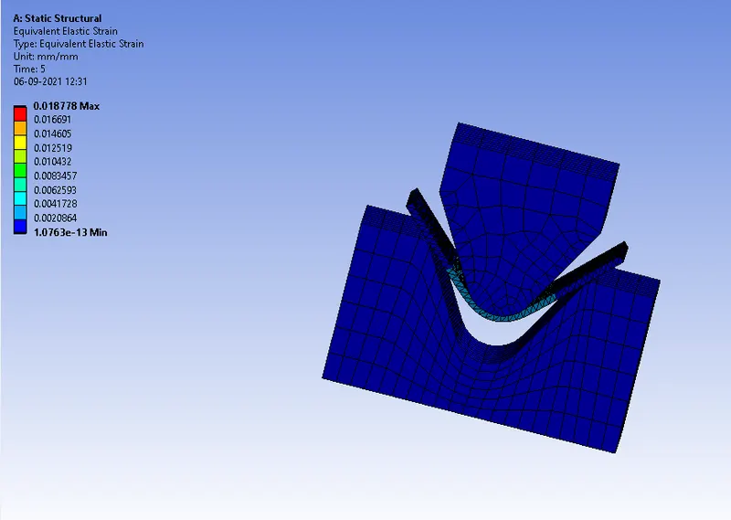
Fig . 13 Equivalent Strain - Copper Alloy
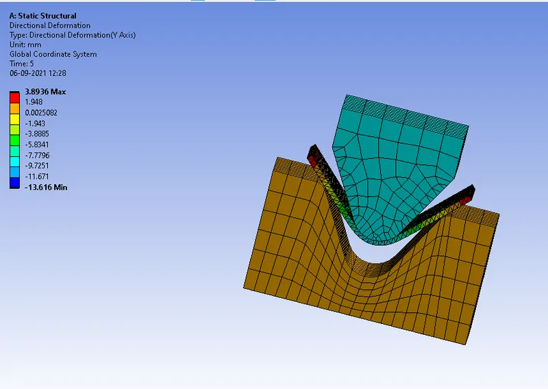
Fig. 11 Deformation in Y direction - Copper Alloy
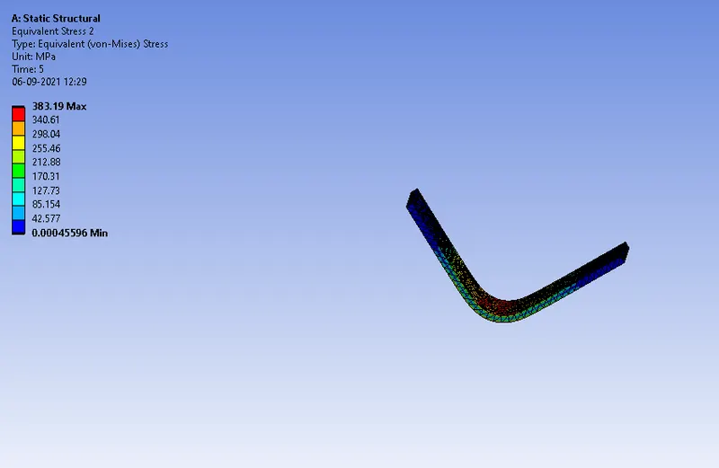
Fig . 12 Equivalent Stress Sheet - Copper Alloy
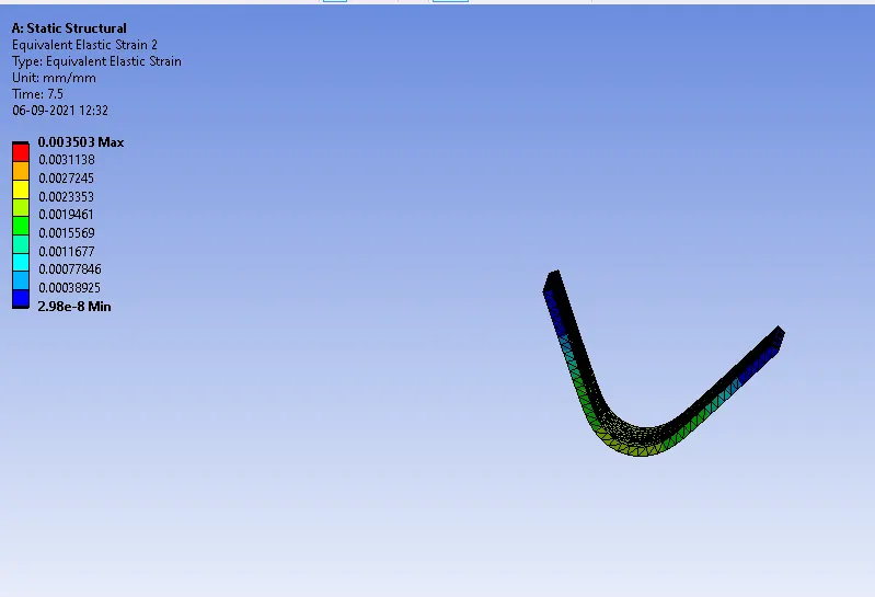
Fig . 12 Equivalent Strain Sheet - Copper Alloy
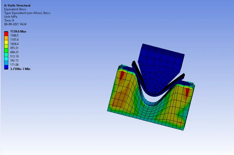
Fig . 14 Equivalent Stress - Magnesium Alloy
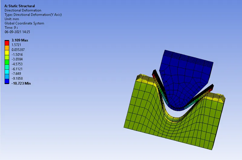
Fig . 15 Deformation - Magnesium Alloy
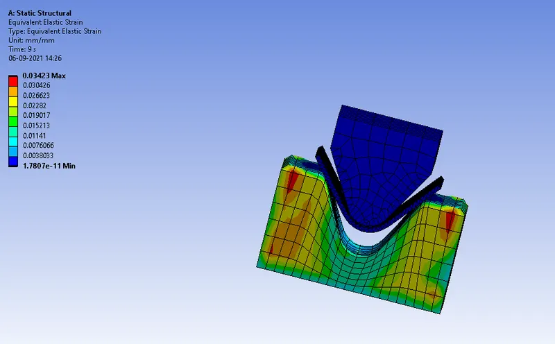
Fig . 16 Equivalent Strain - Magnesium Alloy
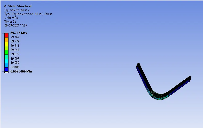
Fig . 17 Equivalent Stress Sheet - Magnesium Alloy
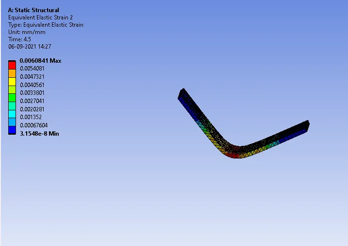
Fig . 17 Equivalent Strain Sheet - Magnesium Alloy
| SL No | Output Solution | Material Assignment for Plates | ||
| Aluminium Alloy 1199 | Magnesium Alloy NL | Copper Alloy NL | ||
| 1 | Equivalent Stress Sheet (Mpa) | 2702.3 | 89.175 | 383.19 |
| 2 | Equivalent Stress (Mpa) | 5881.1 | 1539.6 | 2064.6 |
| 3 | Directional Deformation (mm) | 4.3282 | 3.109 | 3.8936 |
| 4 | Equivalent Strain | 0.043602 | 0.03423 | 0.018778 |
| 5 | Equivalent Strain Sheet (Mpa) | 0.002412 | 0.0060841 | 0.003503 |
4. CASE 2 - RESULTS
In this case, the material assigned to the plate is Aluminum Alloy and the coefficient of friction value for the contact faces is set to 0.19
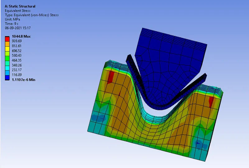
Fig . 18 Equivalent Stress - Aluminum Alloy
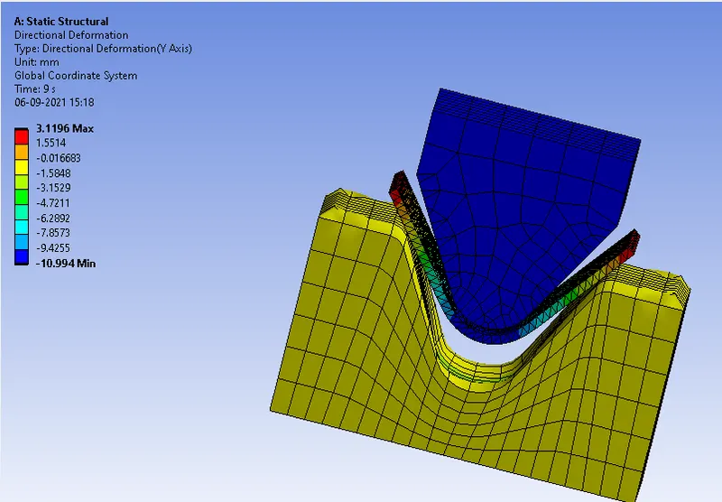
Fig . 19 Deformation - Aluminum Alloy
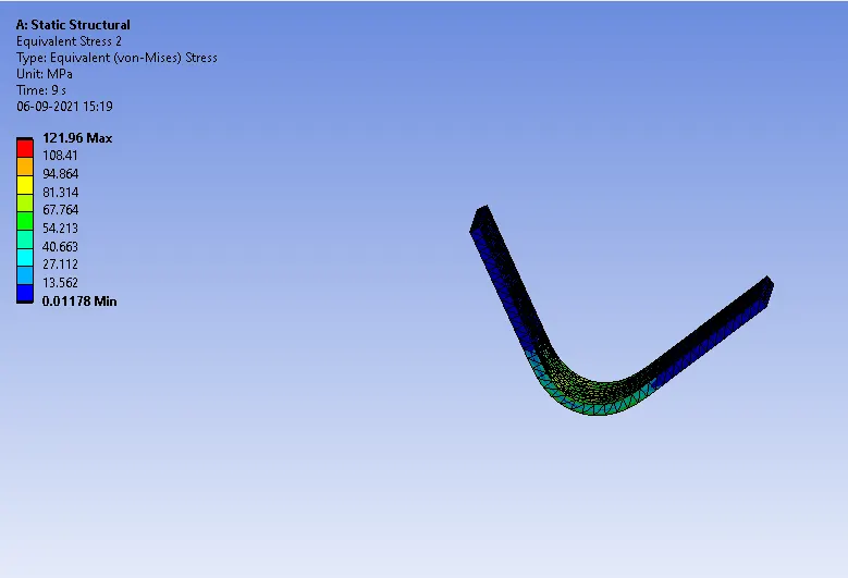
Fig . 20 Equivalent Stress Sheet - Aluminum Alloy
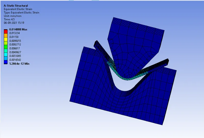
Fig . 21 Equivalent Strain - Aluminum Alloy
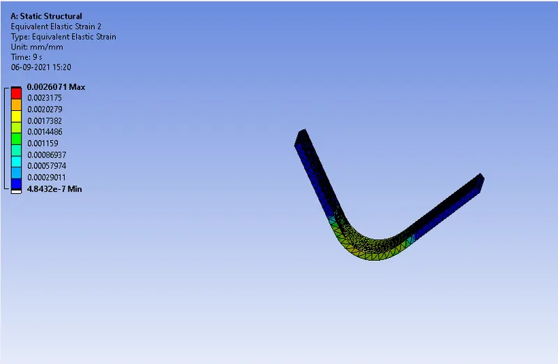
Fig . 20 Equivalent Strain Sheet - Aluminum Alloy
| SL No | Output Solution | Material Assignment for Plates | |||
| CASE1 CASE2 | |||||
| Aluminium Alloy 1199 | Magnesium Alloy NL | Copper Alloy NL | Aluminium Alloy NL | ||
| 1 | Equivalent Stress Sheet (Mpa) | 2702.3 | 89.175 | 383.19 | 121.96 |
| 2 | Equivalent Stress (Mpa) | 5881.1 | 1539.6 | 2064.6 | 1044.8 |
| 3 | Directional Deformation (mm) | 4.3282 | 3.109 | 3.8936 | 3.1196 |
| 4 | Equivalent Strain | 0.043602 | 0.03423 | 0.018778 | 0.014888 |
| 5 | Equivalent Strain Sheet (Mpa) | 0.002412 | 0.0060841 | 0.003503 | 0.0026071 |
It can be seen that the value of equivalent stress in the plate increased sharply when the Aluminium Alloy NL is assigned to the plate while the other values are less as compared to CASE-1 results.
5. CASE 3 - RESULTS
In this case, the material assigned to the plate is Aluminum Alloy and the mesh size considered for the plate is 0.7 mm. This restricted the number of nodes and elements to 28672 and 12787 respectively (within the academic version limit)
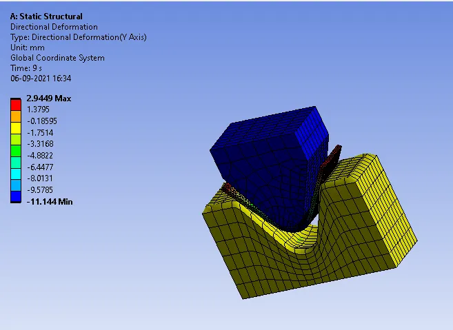
Fig . 22 Deformation - Aluminum Alloy fine mesh
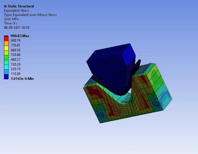
Fig . 23 Equivalent Stress - Aluminum Alloy fine mesh
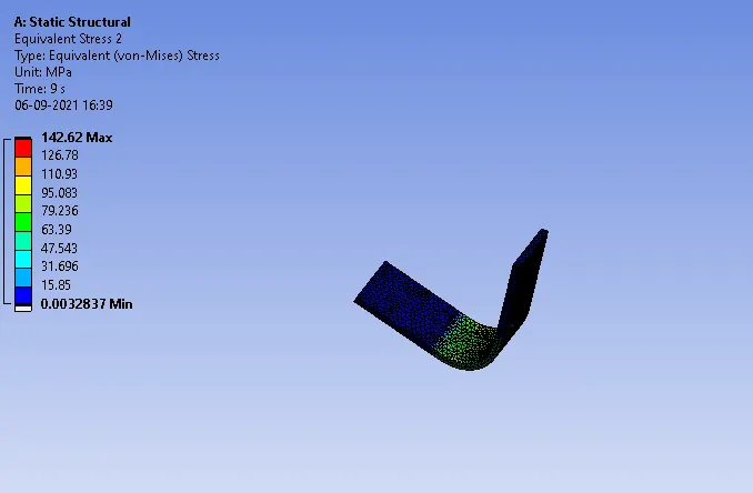
Fig . 24 Equivalent Stress Sheet - Aluminum Alloy fine mesh
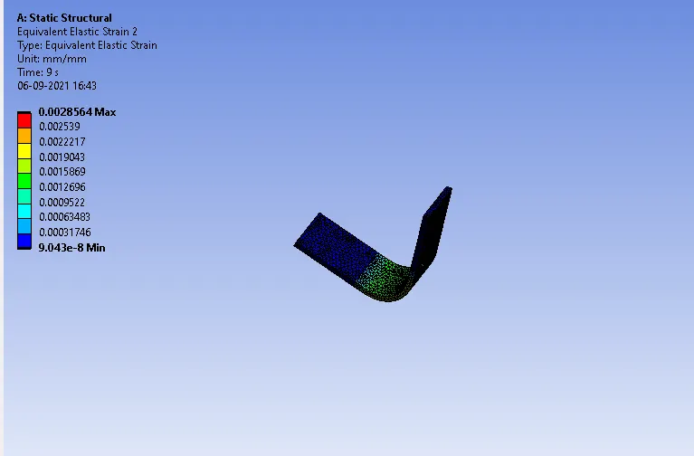
Fig . 24 Equivalent strain Sheet - Aluminum Alloy fine mesh
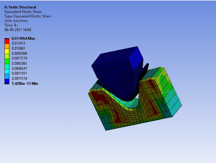
Fig . 25 Strain - Aluminum Alloy fine mesh
| SL No | Output Solution | Material Assignment for Plates | |||
| CASE1 CASE3 | |||||
| Aluminium Alloy 1199 | Magnesium Alloy NL | Copper Alloy NL | Aluminium Alloy NL | ||
| 1 | Equivalent Stress Sheet (Mpa) | 2702.3 | 89.175 | 383.19 | 142.62 |
| 2 | Equivalent Stress (Mpa) | 5881.1 | 1539.6 | 2064.6 | 990.83 |
| 3 | Directional Deformation (mm) | 4.3282 | 3.109 | 3.8936 | 2.9449 |
| 4 | Equivalent Strain | 0.043602 | 0.03423 | 0.018778 | 0.13964 |
| 5 | Equivalent Strain Sheet (Mpa) | 0.002412 | 0.0060841 | 0.003503 | 0.0028564 |
When the mesh of the plate is refined further it is observed that maximum stress occurs in the plate while the stress, strain and deformation in other members, i.e, the die and punch are less as compared to CASE-1 results.
CONCLUSION:-
Various Results obtained from these analyses are summarized in the given table. A lot of various and different parameters were used in this analysis such as different materials, different coefficients of friction and mesh refinements. At the end of this, we get satisfactory results.