Week 2 Railwheel and Track
AIM:-
To simulate the Railwheel and track for their lifecycle and the stress, strain, and total deformation provided by the wheel running on the track by the given forces.
OBJECTIVE:-
The main focus of this component is to evaluate the result of the product life cycle and the stress, strain, and total deformation in the static structural material. This component is to be examined by two cases
Case 1: Load of 100000 N.
Case 2: Load of 5 times of 100000N.
And Implement user-defined results and compare both results in all aspects of the evaluation.
INTRODUCTION:-
Rail wheel concept
The train wheel or a rail wheel is specially designed for use of railway tracks. This rolling component (wheel) is especially pushed onto on axle and mounted directly on a railway carriage or locomotive or indirectly we can say boogie. This wheel is cast or forged and is heated or treated to have a specific hardness. New wheels are trued, using a lathe, to a specific profile before being pressed onto an axle. All wheels profile must be regularly checked to ensure proper interaction between the rail and wheel. Incorrectly trued or worn out wheels can increase rolling resistance, reduce energy efficiency and even cause a derailment.
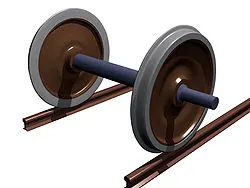
Fig 1: Rail wheel and track
Wheel Geometry and Flange, most train wheels have a conical geometry, which is the initial means of keeping the train motion aligned with the track. The train wheels have a flange on one side to keep the wheels and hence the train, running on the rails when the limits of geometry-based alignment are reached.
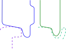
Fig 2: Wheels arrangement
PROCEDURE:-
For the simulation of the rail wheel and track the static structural material which is default has been used to evaluate the result.
First, the geometry is imported and then opened directly in the mechanical module.
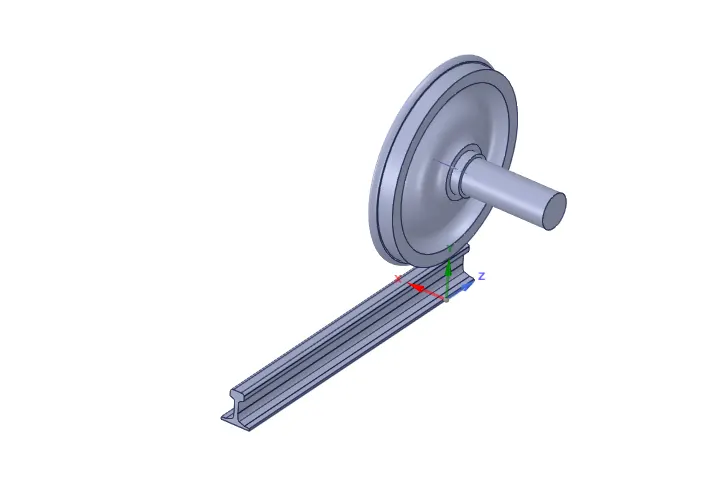
Fig 3: Geometry of rail wheel and track
To set up certain parameters and loads for the simulation process of the rail wheel and track the materials is default as structural steel with the property mentioned below.
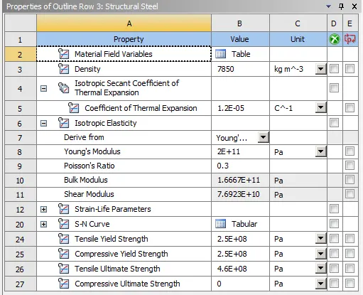
Fig 4: Properties of static structural
To understand the contact between the rail wheel and track they are renamed based on the definition and then flip contact to the target.
Two contacts are provided between them:
1) Frictional- Wheel to running rail.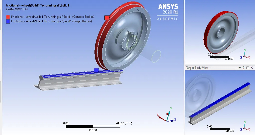
Fig 5: Contact between wheel to running rail
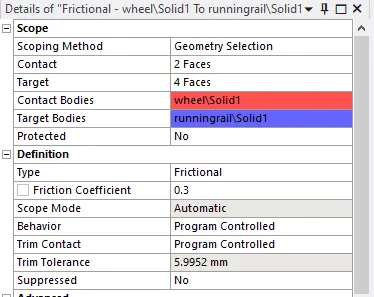
Fig 6: Contact parameters wheel to the rail track
2) Frictionless - shaft to the wheel.
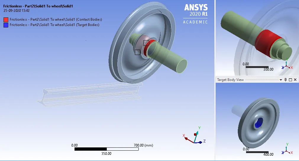
Fig 7: Contact between the shaft and the wheel
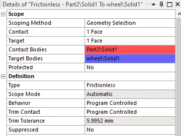
Fig 8: Contact parameters shaft to the wheel
After giving the parameters, the joints to be applied for the application to be run on the simulation process while evaluating the result.
The first joined is applied is the fixed joint for the non-moment of the track while running the wheel on them.
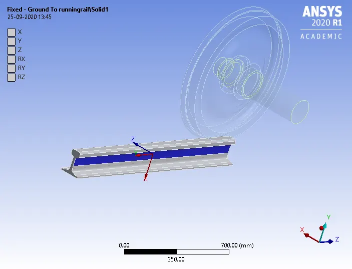
Fig 9: Fixed joint
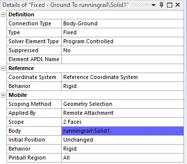
Fig 10: Parameters of fixed joint
Second is the transitional joint given to the shaft, was the shaft is attached to the wheel the forces act on the shaft will be transitional to the wheel.
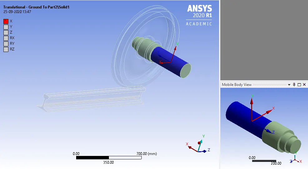
Fig 11: Transitional joint shaft

Fig 12: Parameters of transitional joint
The final joint is the planar joint which provided to the wheel.
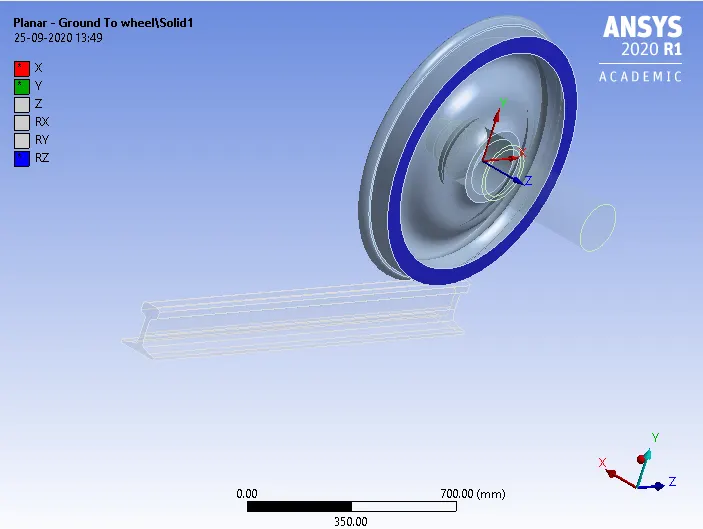
Fig 13: Planar joint
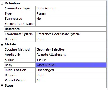
Fig 14: Parameters of Planar joint
Mesh
Element size: 50mm
and the three faces are selected with the facing size around 35mm.
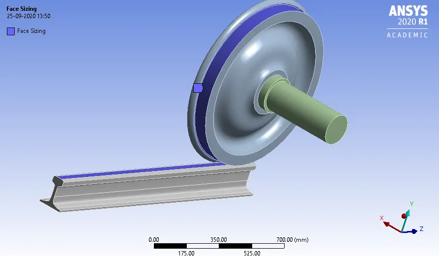
Fig 15: Mesh facing surfaces
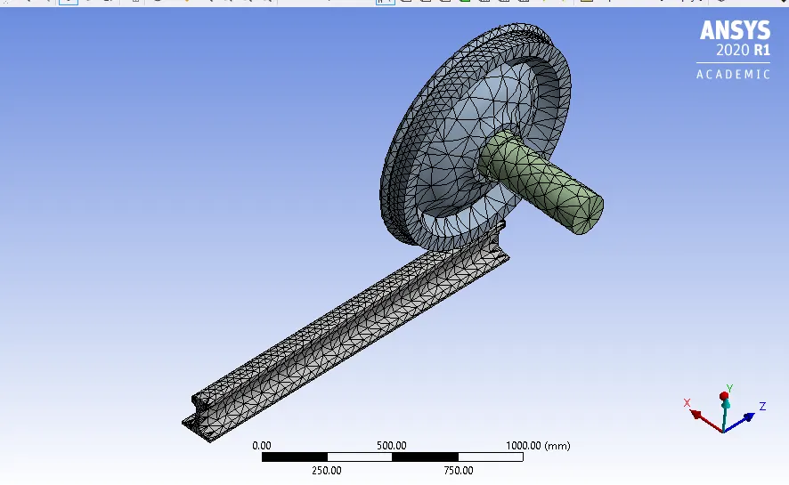
Fig 16: Mesh

Fig 17: Mesh statistics
Giving the appropriate parameters in the analysis setting with some joint load that need to apply on the geometry.
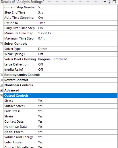
Fig 18: Analysis settings
After getting the parameters of the analysis setting two loads are applied
1) Bearing load with the value of 100000N
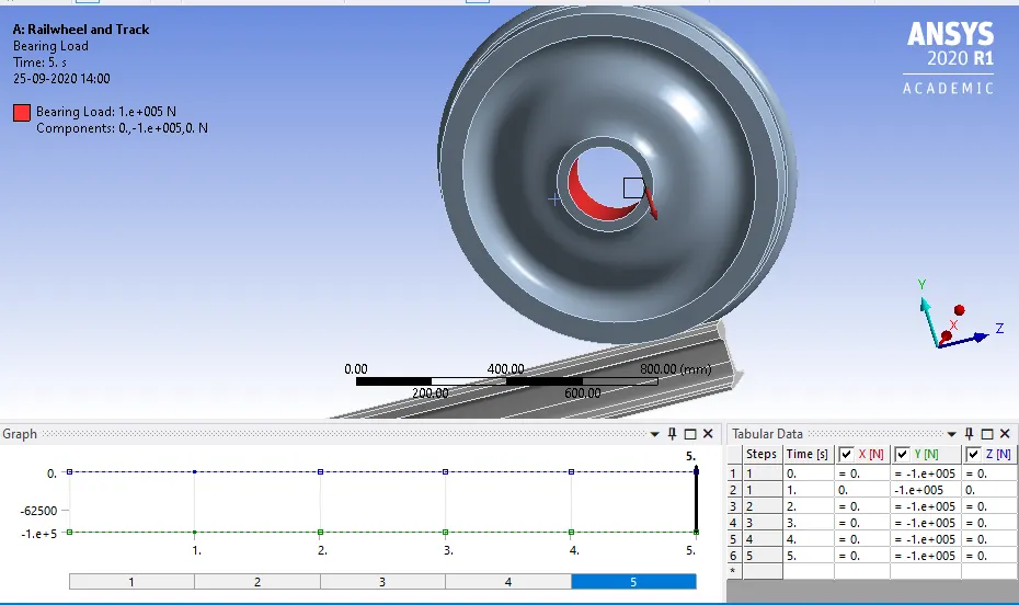
Fig 19: Bearing load
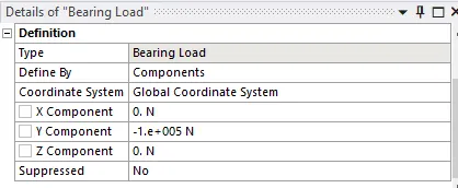
Fig 20: Bearing load parameters
2) Joint displacement
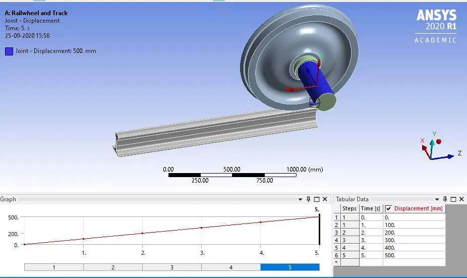
Fig 21: Joint displacement
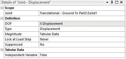
Fig 22: Joint displacement parameters
The following parameters need to be evaluated for the result of the rail wheel and track:
- Equivalent Von misses stress.
- Total deformation.
- Life cycle.
- User-defined result.
Fig 23: Define the solution parameters
RESULTS
Case 1: Bearing load 500KN and 100KN. Compare the result for total deformation, Equivalent stress, and life under both loads.
Bearing Load 100KN
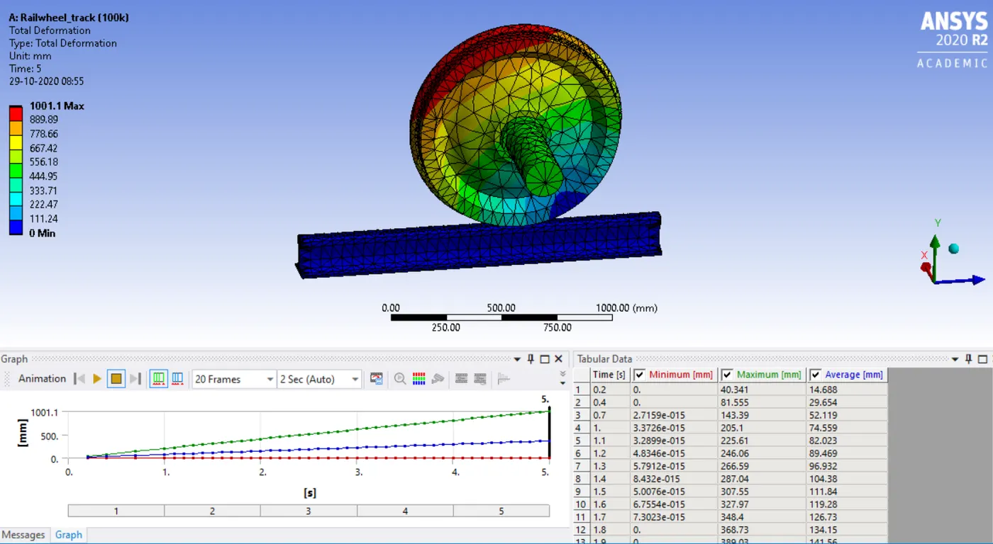
Fig 22: Total deformation
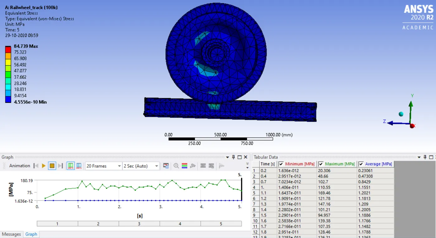
Fig 23: Equivalent stress
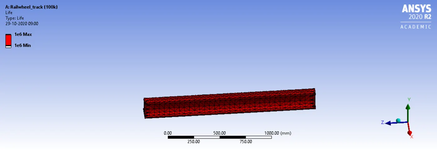
Fig 24: The life cycle of track
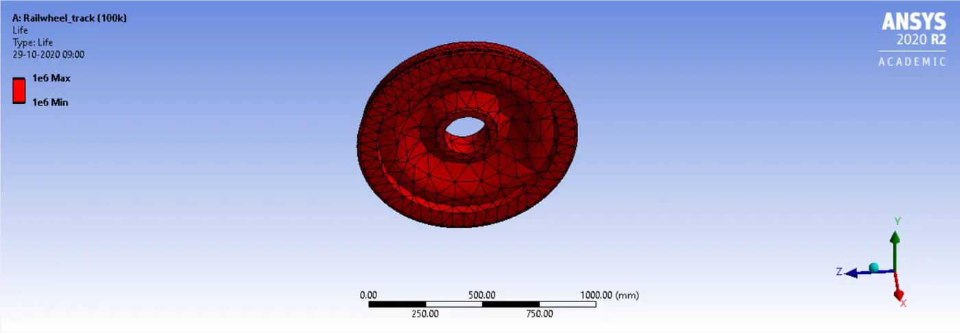
Fig 25: The Life of railwheel
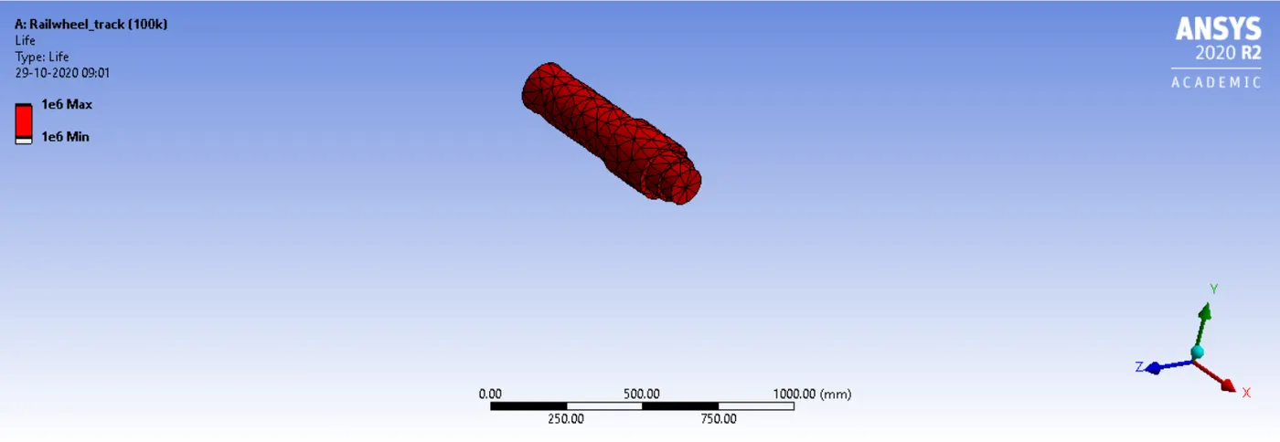
Fig 26: The life cycle of shaft
Bearing Load 500KN
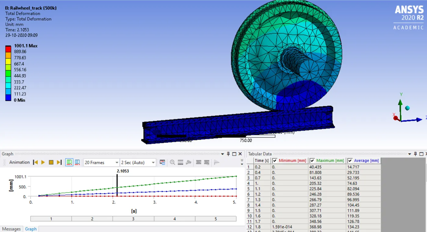
Fig 27: Total deformation
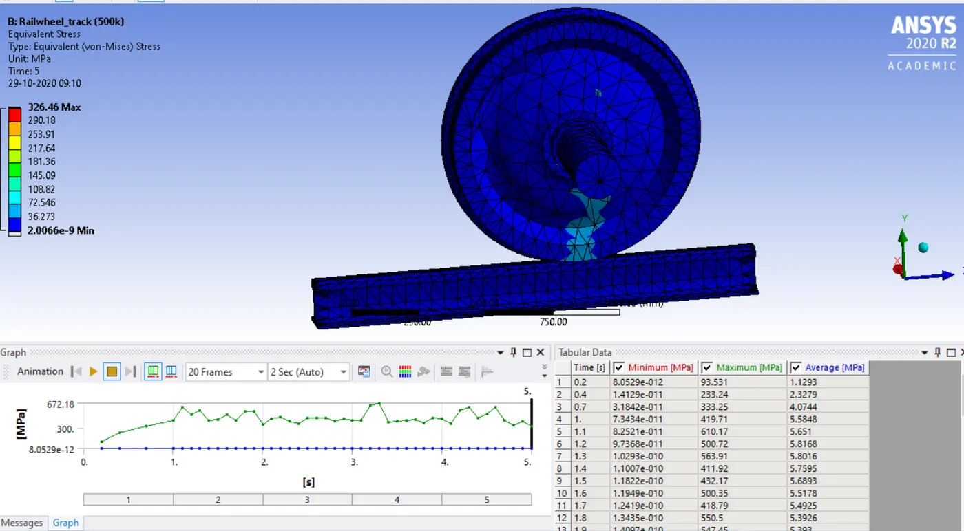
Fig 28: Equivalent stress
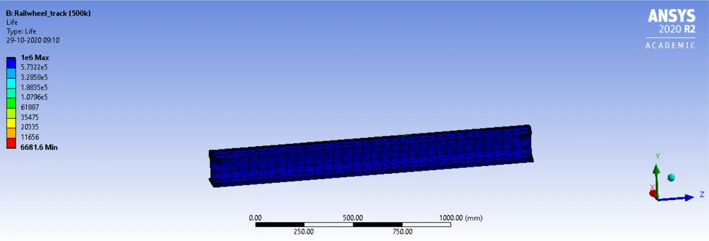
Fig 29: Life of track
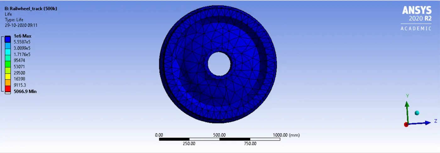
Fig 30: Life of wheel
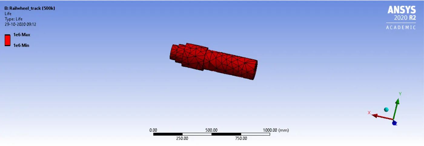
Fig 31: Life of wheel
Comparison of result
| Sr No | 100KN | 500KN |
| Total deformation Min (mm) | 0 | 2.8422e-014 |
| Total deformation Max (mm) | 1001.1 | 1001.1 |
| Total deformation Avg (mm) | 367.11 | 367.11 |
| Equivalent stress von mises Min (MPa) | 4.5556e-010 | 2.0066e-009 |
| Equivalent stress von mises Max (MPa) | 84.739 | 326.46 |
| Equivalent stress von mises Avg (MPa) | 1.1504 | 5.334 |
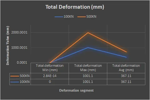
Fig 32: Plot for Total deformation (mm)
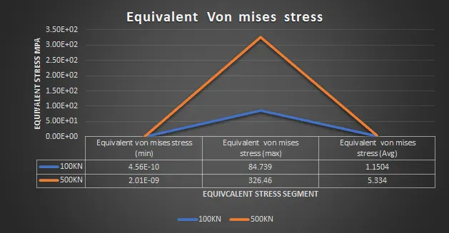
Fig 33: Plot for Equivalent von misses stress
The result shows that the load increases, as the force on the trackwheel simulation the equivalent stress and deformation increases, the force is directly proportional to the stress value. And the life cycle for both loads 1e^6 max.
Case 2: User-defined Result
To evaluate the user-defined result for both loads as I have taken the result for both loads. The expression used to evaluate the result expression used is UX + UY +UZ and the output unit is displacement.
Load 100KN
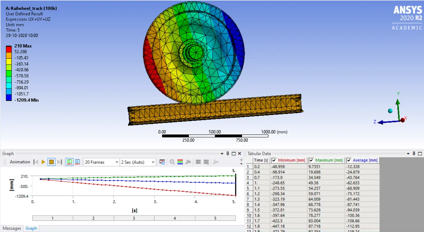
Fig 34: User-defined result
Load 500KN
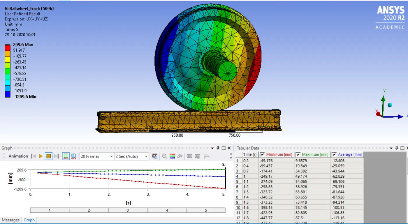
Fig 35: User-defined result