Week 6 - Creating connection for Rear door
AIM:-
To give suitable connections for the given rear door component, create and apply different PIDs for different components.
PROCEDURE:-
1.Import the rear door in ANSA as shown below.
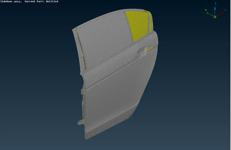
2.Next create new PIDs goto Mesh→Macros→Set PID→Faces/Shells→Select the shells→New→P shell as shown below.
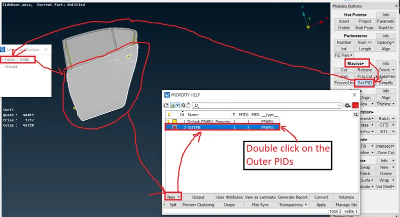
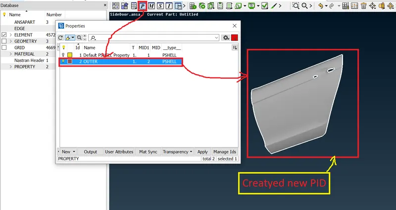
3.Next see the properties it shows as shown below.
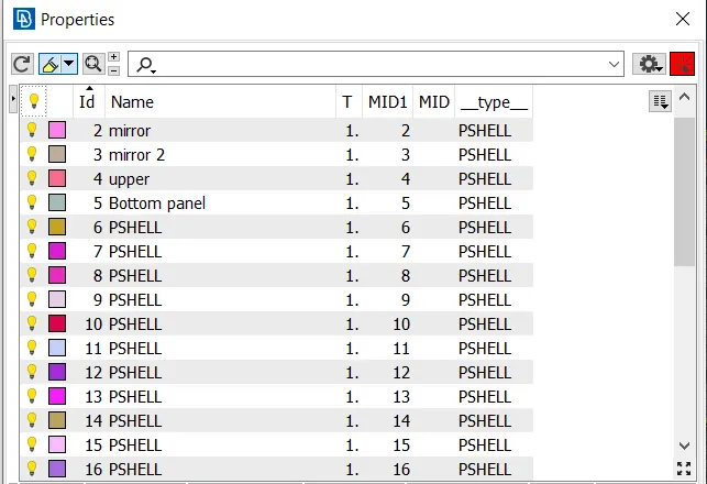
4.Follow the above steps created the different PIDs for different components as shown below.
5.Next Check the Geometry and observe were give the connections were found.
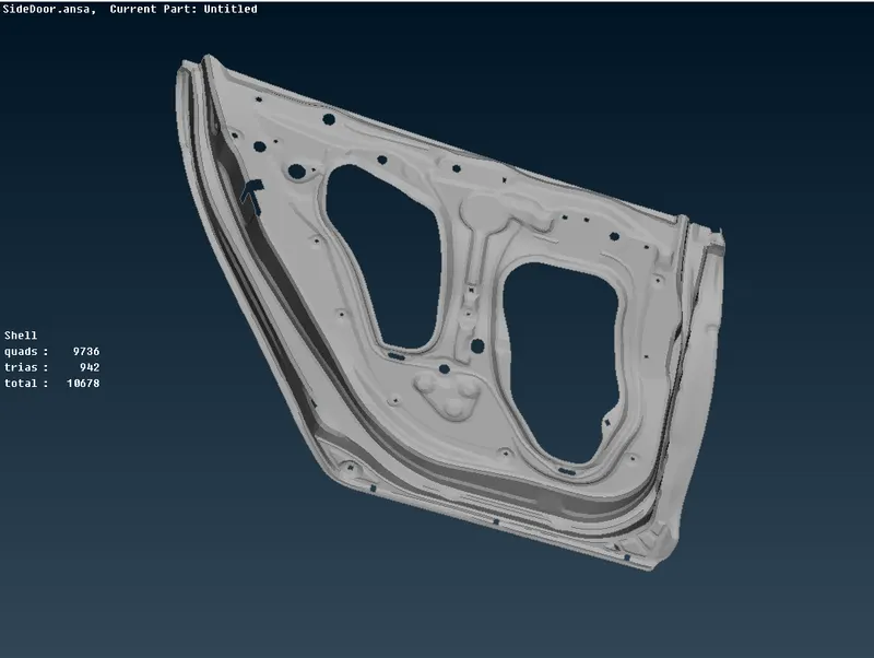
6.See the above image there is a lot of holes so I'am created the RBE2 connection.
7.Goto the Decks→Nastran→Elements→RBE2→Many nodes as shown below.
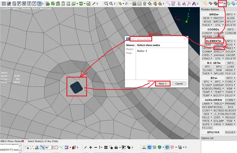
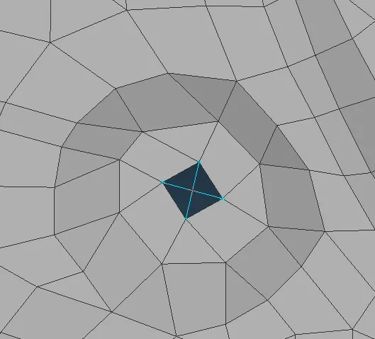
8.Follow the above steps create RBE2 connections as shown below.
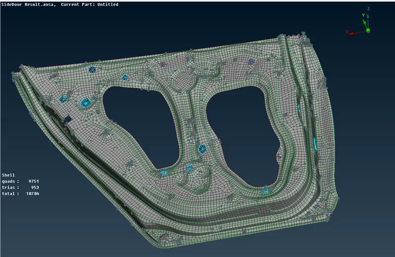
9.Next create the bolts at the hinge area as shown below.
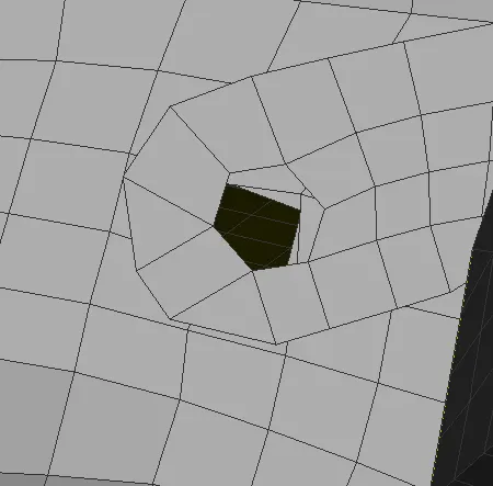
10.create a 3D point goto the Topo→Points→on COG as shown below.
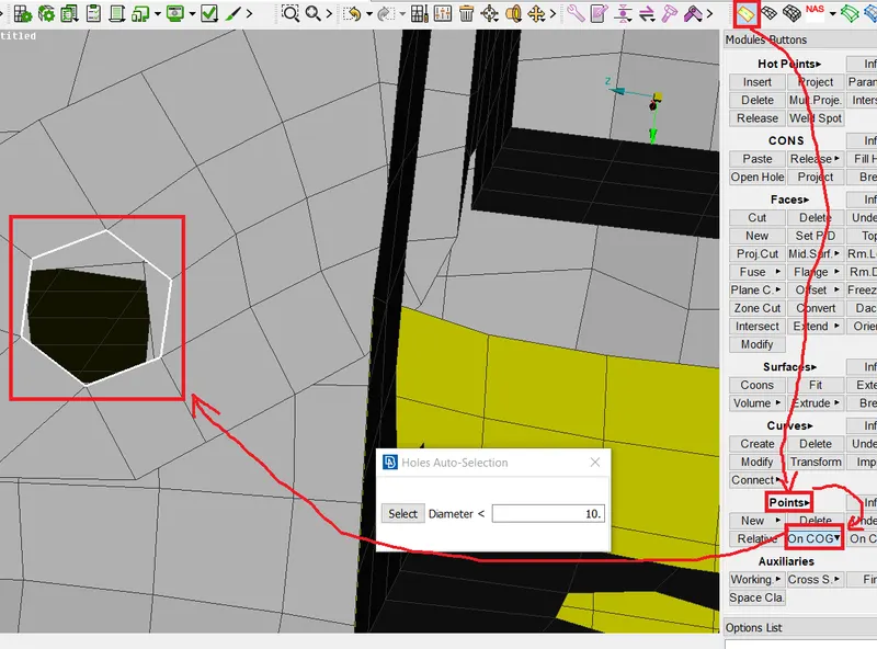
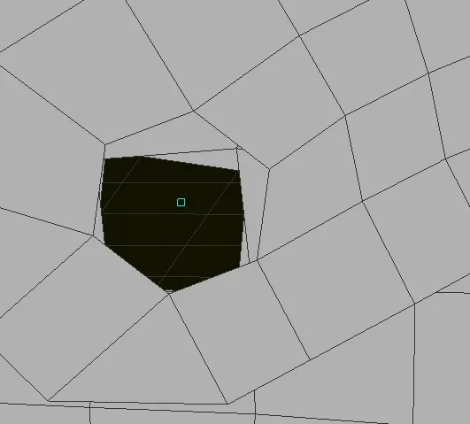
11.Next convert the 3D point to bolt go to Assembly→Convert→3D Points→Select the 3D point→Bolt→Ok as shown below.
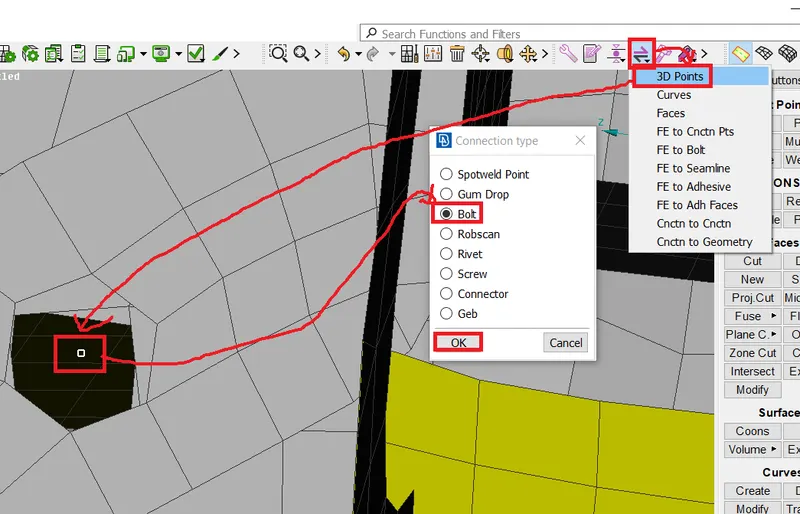
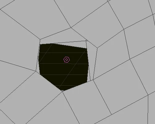 successfully completed 3D point is converted into the bolt as see the image it shows bolt symbol.
12.Next goto Assembly→Connection Manager as shown below.
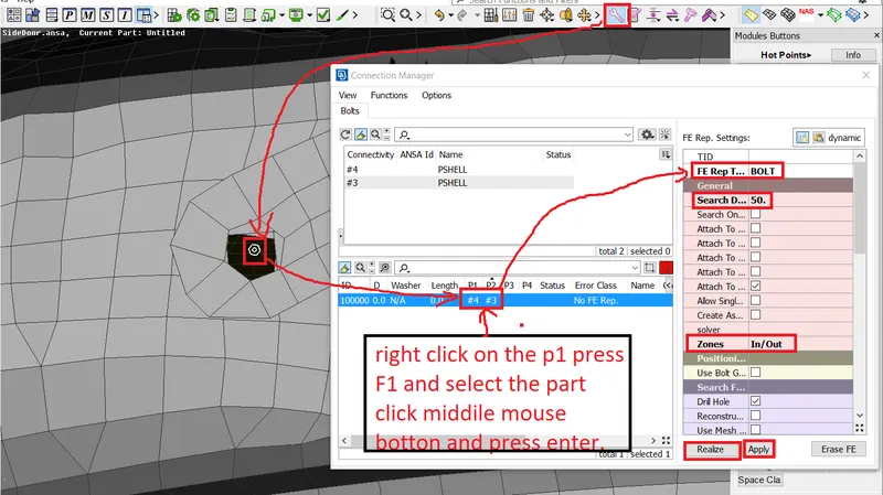
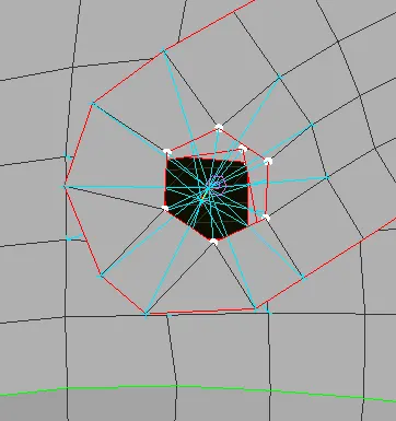
13. In the hinge area taking the RBE2(many nodes) connection is generated as shown below.
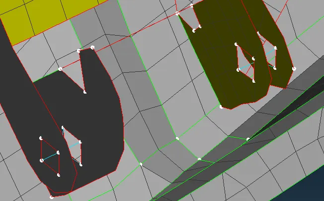
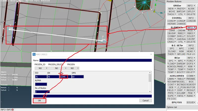
14.Next join the two RBE2 connections here take the RBE2 (two nodes) as shown below.
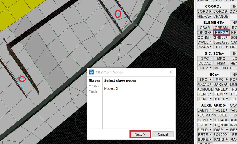
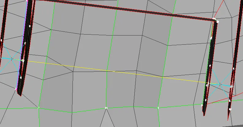
15.This hinge only Z-direction moves so except the Z direction all directions are locked as shown below.
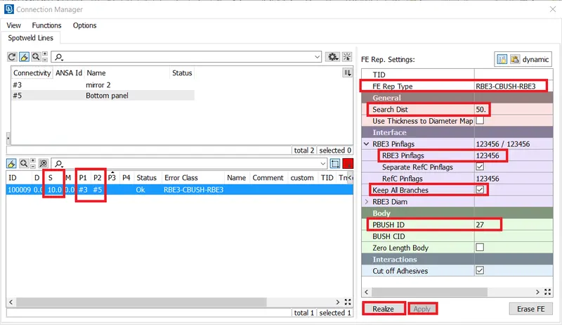
16.Next go to the mirror area here create the C bush.
17.create curve at the boundary of mirrors and convert the curve to spot line goto the Conection manager assign the parts and
FE rep type is RBE3-CBUSH-RBE3 as shown below.
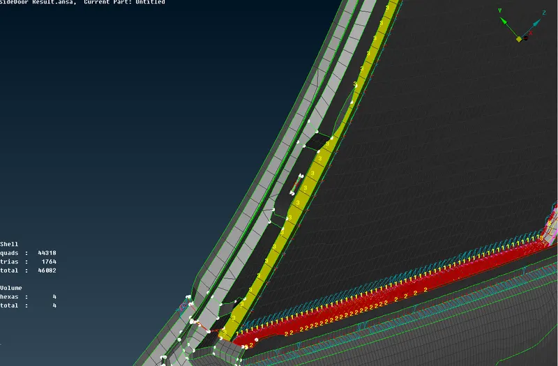
18.Repeate the above step and created Cbush connections for all mirror side as shown below.
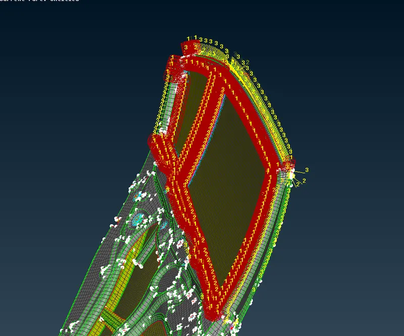
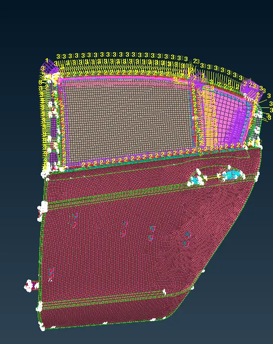
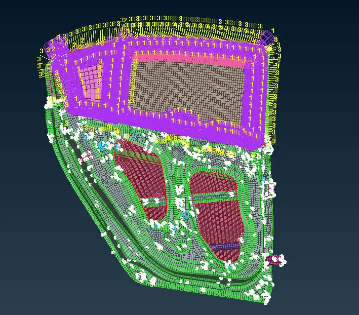
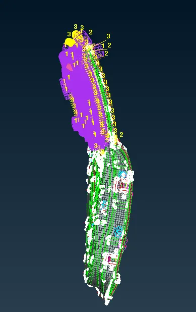
19.Observe the components giving the suitable connections as shown below.
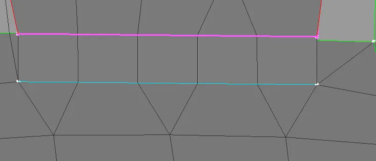 Y-jiont shell.
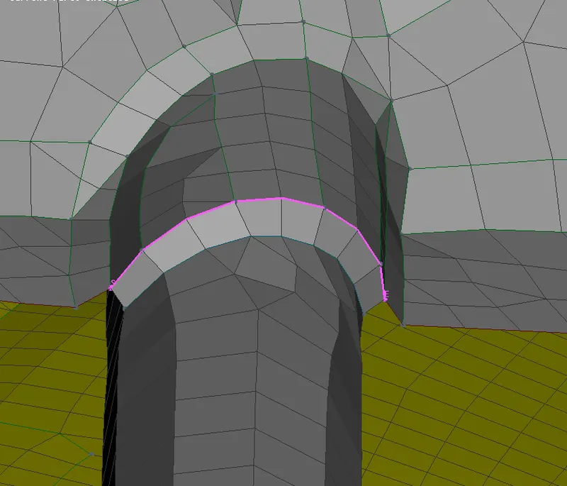 Overlap shell.
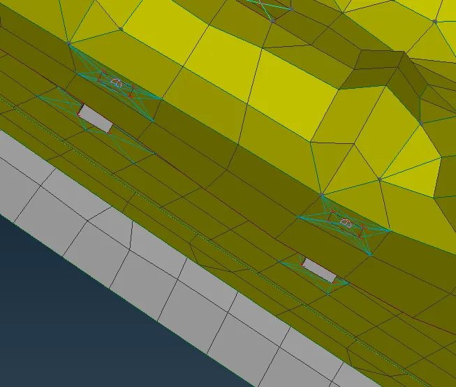 Spot weld conection.
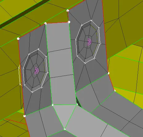 Rivet conection.
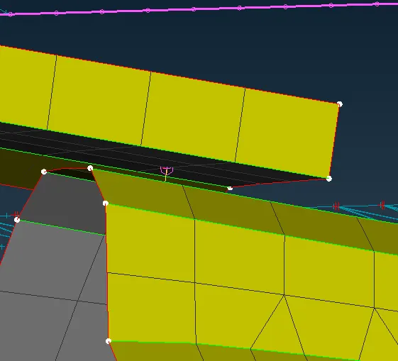 screw conection.
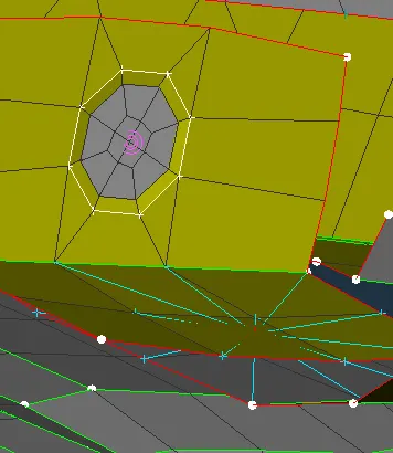
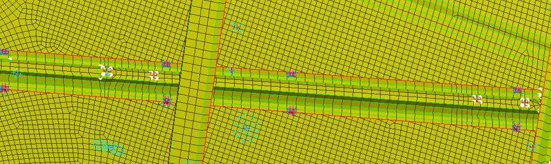

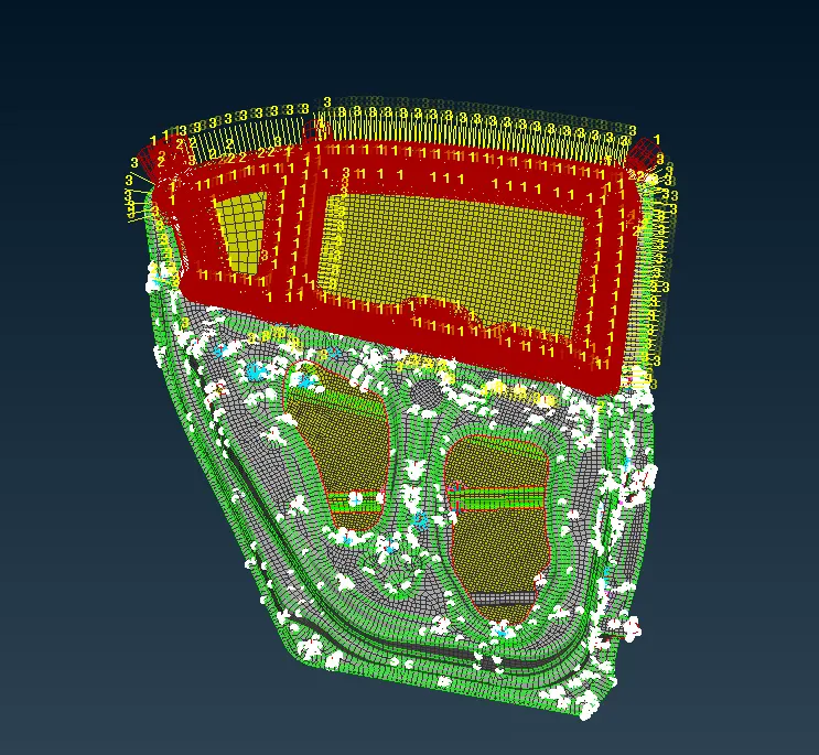
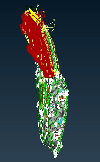
20.Finally completed the all connections as shown below.
LEARNING OUTCOMES:
1.How to convert the points and curves into connecting lines and points using the convert and connection manager tool.
2.How to assign property and certain values to the connection tools.
3.How to create RBE2 elements using nodes in the Nastran deck.
4.How to choose the connections for different areas.
CONCLUSION:-
The PIDs are assigned to the various parts in the given model. Various connections like BOLT, Spotweld, C bush,Rivet and RBE2 are created and realized. All the given objectives are satisfied.