week-11 Joint creation and Demonstration
AIM:-
To create revolute, cylindrical, and translational joints between two rigid bodies and two deformable bodies Using the Ls-Dyna Solver
Joints:-
A mechanical joint is a section of a Machine that is used to connect one or more mechanical parts to another. Mechanical joints may be temporary or permanent, most types are designed to be disassembled. Most mechanical joints are designed to allow the Relative Movement of these mechanical parts of the machine in one Degree of Freedom and restrict movement in one or more others.
Types of Joints:-
- Mechanical joints are broadly classified into two classes non-permanent joints and permanent joints.
- Non-permanent joints can be assembled and dissembled without damaging the components.
- Examples of such joints are threaded fasteners (like screw-joints), keys and couplings, etc.
- Permanent joints cannot be dissembled without damaging the components. These joints can be of two kinds depending upon the nature of the force that holds the two parts.
- The force can be of mechanical origin, for example, riveted joints, joints formed by press or interference fit, etc, where two components are joined by applying mechanical force.
- The components can also be joined by molecular force, for example, welded joints, brazed joints, joints with adhesives, etc.
Here The The Principles of revolute, cylindrical, and translational joints between two rigid bodies and two deformable bodies are Demonstrated
PROCEDURE:-
1. REVOLUTE JOINT :
A revolute joint (also called pin joint or hinge joint) is one Degree of Freedom Kinetic Pair used frequently in mechanisms and machines. The joint constrains the motion of two bodies to pure rotation along a common axis. The joint does not allow translation or sliding linear motion, a constraint not shown in the diagram. Almost all assemblies of multiple moving bodies include revolute joints in their designs. Revolute joints are used in numerous applications such as door hinges, mechanisms, and other uni-axial rotation devices.
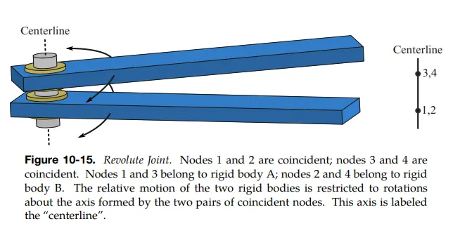
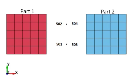
Case-1:Revolute Joint Between Rigid Bodies:-
1. Create Two-4 Noded Shell Using Mesh > Shape Mesher > 4 noded Shell. and enter the Coordinates in P1, P2, P3, P4.
2. Assign 1 shell Component as part and another one as part-2
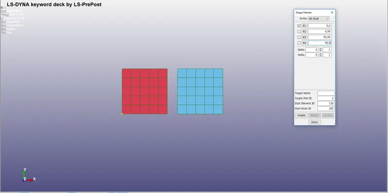
3. Create 2 nodes In between the Shell and note their Id.
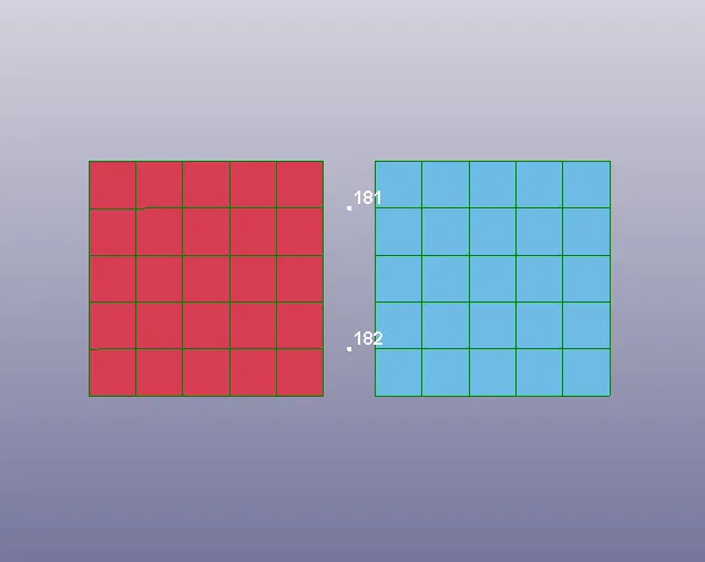
4. Create Another Two nodes Such as 183 and 184 which Coincide with 181 and 182
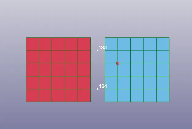
5. Create a Node set consisting of Nodes 181 and 182 and another Nodeset consisting of 183 and 184
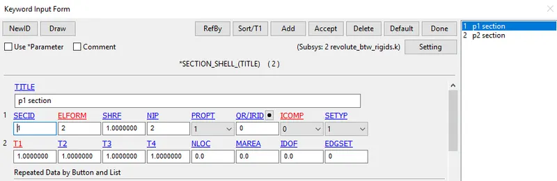
6. Create a Section for the Shell components with ELFORM=2 and with thickness 2
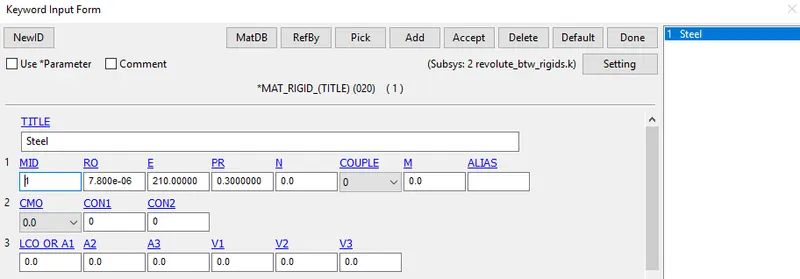
7.MAT_RIGID card is assigned with the Properties of Steel
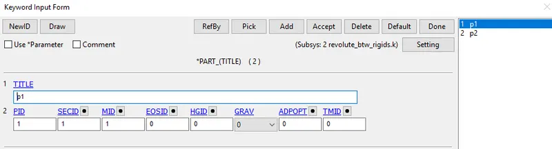
PART CREATION:-
1. Assign the Section and Material to the 2 parts created
CONSTRAINED_EXTRA_NODES:
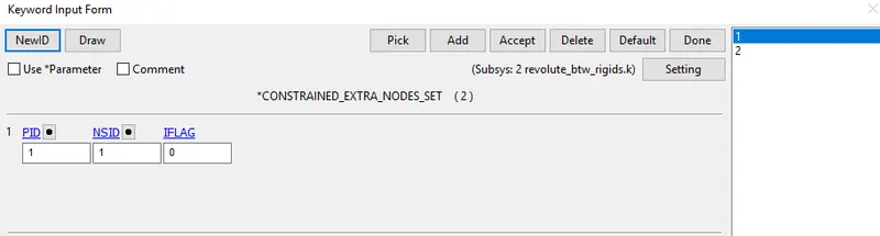
1. The Node set ID Which contains Nodes 181,182 is considered as Fixed Nodes assigned to the part-1 which is also Fixed
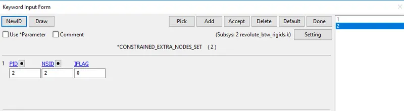
2. The Node Set ID Which Contains Nodes 183, 184 Which in Coincided With 181 and 182 is Considered as Moving Nodes Is Assigned to part 2
Constrained_Joint_Revolute:
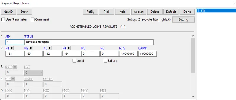
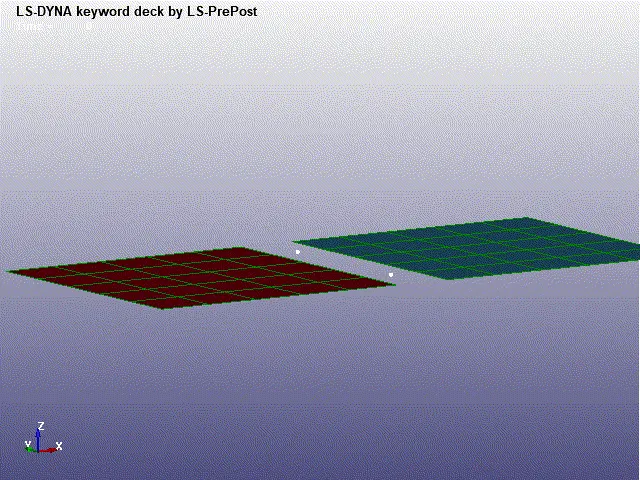
1. Constrained Joint Revolute Is defined And The Nodes which are Coinciding are Entered
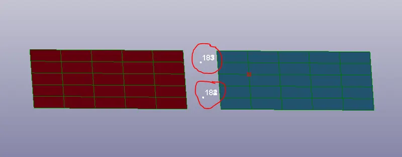
2. From the Image, It is shown that Nodes 181, 183 have coincided and 182 and 184 have Coincided with each other
Displacement:-
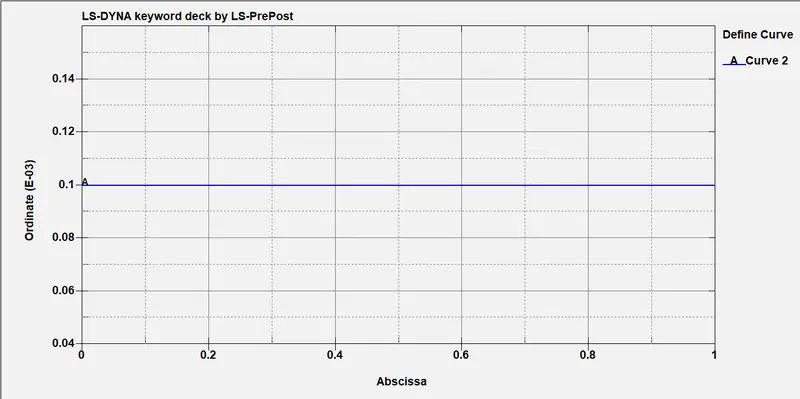
1. Displacement is Given to A node in any one of the Parts By defining displacement Curve, here displacement is given to a node belongs To part-2
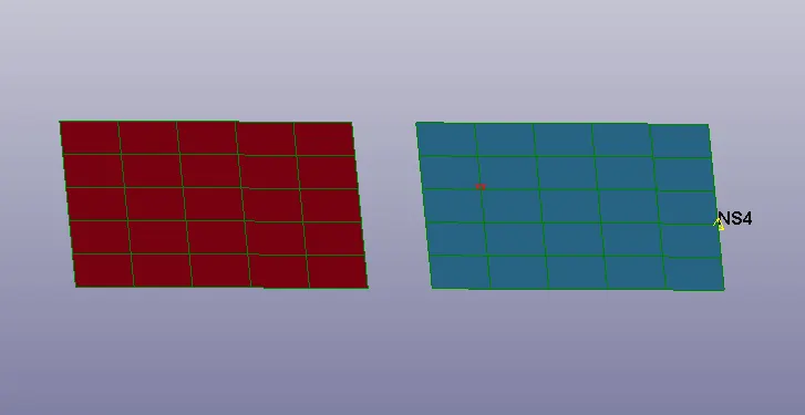
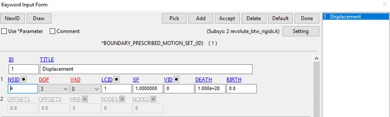
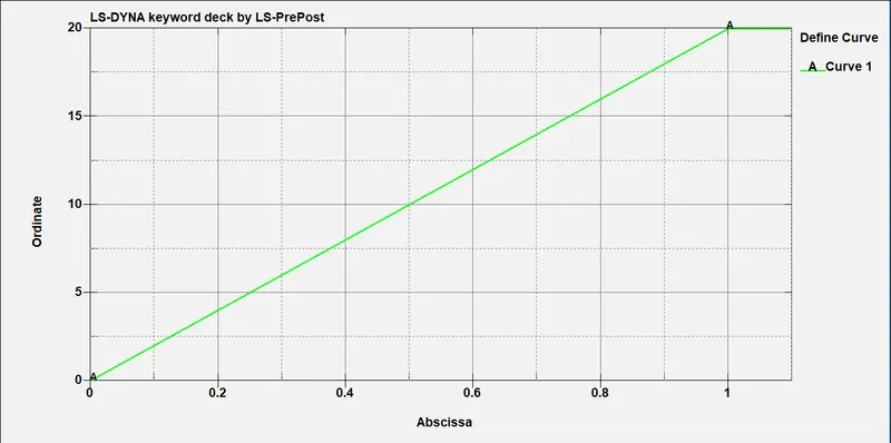
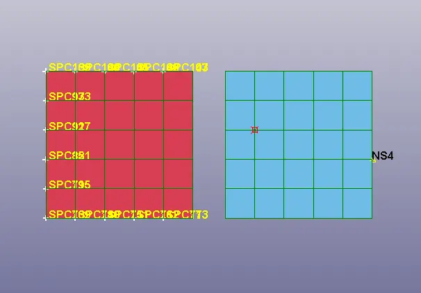
2. As the Displacement Is Given to the Nodes from Part-2, part-1 Is constrained In all DoF's
Control-cards:-
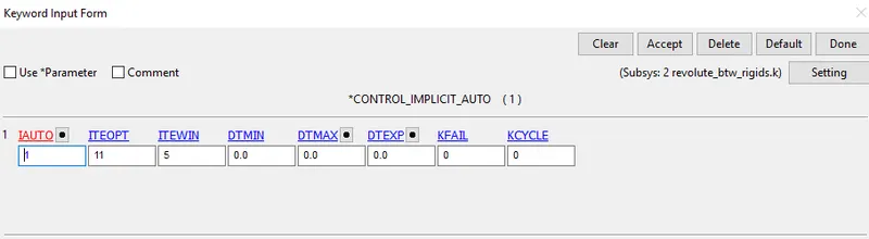
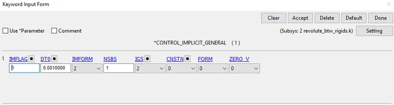
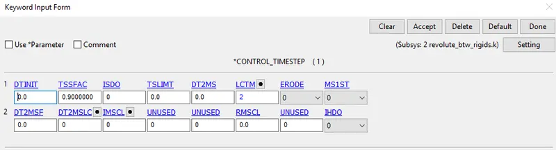
1. Control cards Such as Control Termination, Control implicit Auto, Control Implicit General, And Control Time step Is defined
2. As Displacement is given Implicit Solver Is chosen for Better results
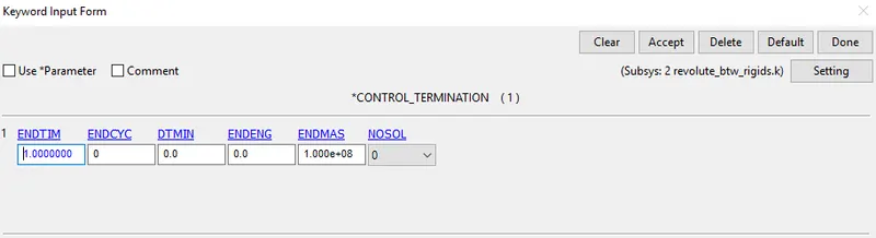
3. Control Termination Card Is defined With the Termination Time 1ms
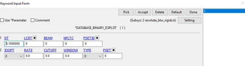
4. Database Binary D3Plot is defined To print the Results at 0.1ms in each interval
5. Contol Timestep Card is defined For Stable Time Step
Results:-
CASE-2:Revolute Joints between Two Deformable Bodies:
1. For Deformable Bodies The Constrained_Extra_Nodes is Replaced with Constrained_Nodal_Rigid_Body
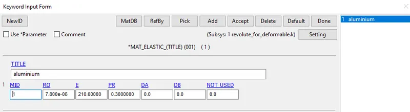
2.Mat_Elastic is defined instead of Mat_Rigid
3.Here Mat_elastic card is defined with The properties of Steel
Procedure:-
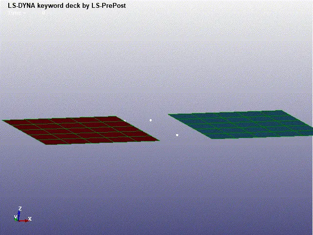
1. Create 4 nodes In the middle individually which is Initially Not coincided with each Other
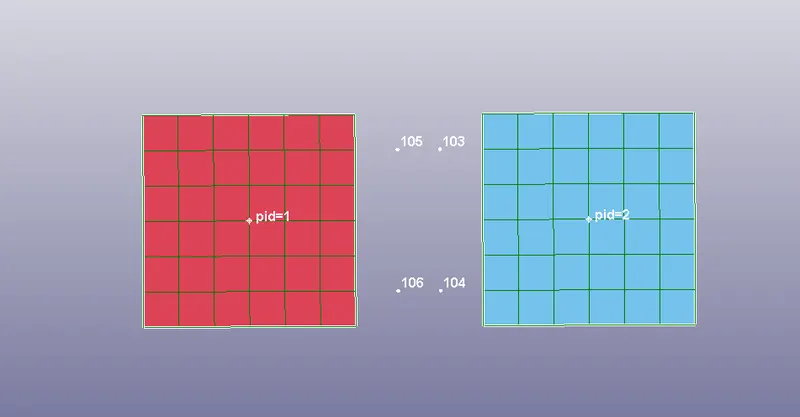
2.Create Nodal rigid Body From Part 1 and 2 as considering 105 and 106 as master node For Part-1 and 103 and 104 as Master Node for Part -2
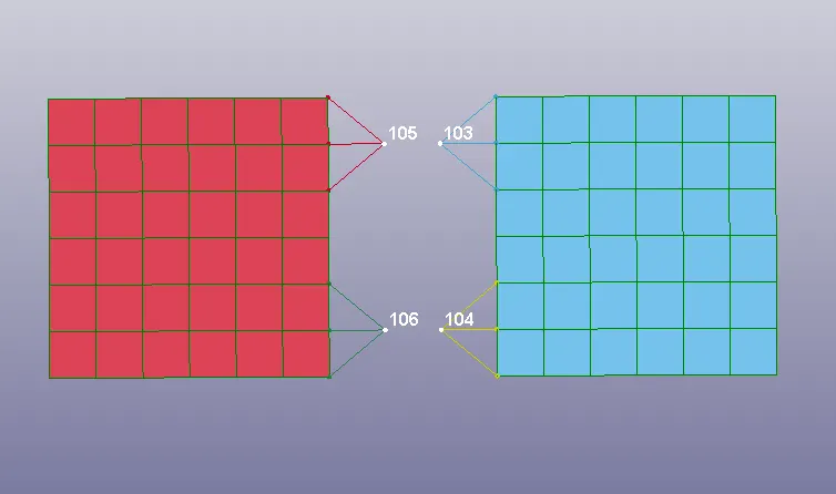
3.Coincide the Nodes 103,105 and 104,105 by Moving the nodes using the Move option in Node edit
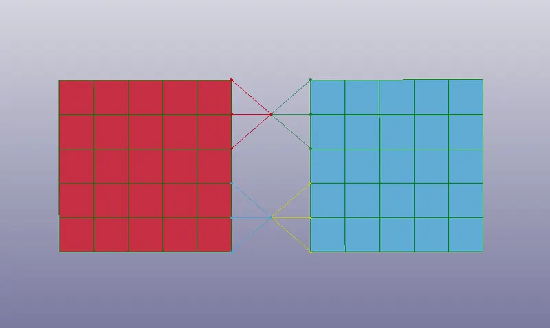
Constained_Joint _Revolute:-
1. Constrained Joint Revolute Is defined And The Nodes which are Coinciding are Entered
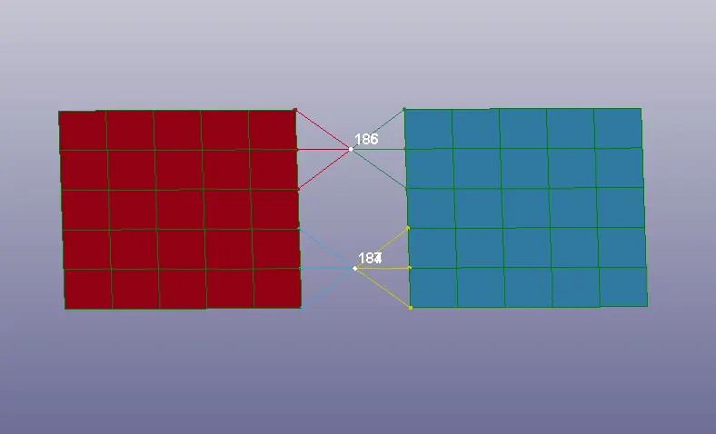
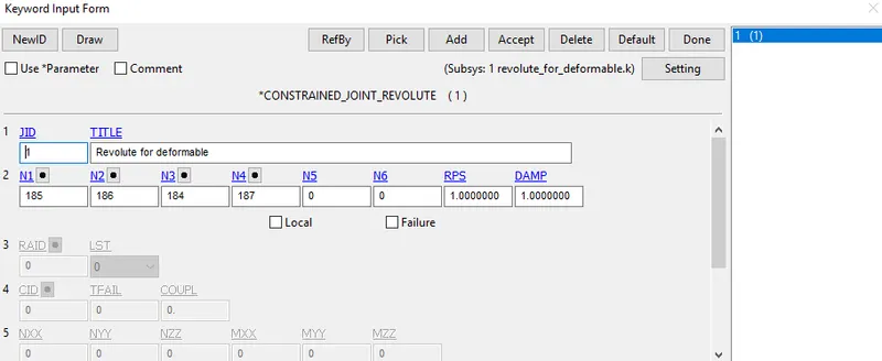
All Other Keywords Are unchanged and the Simulation is executed
2.SPHERICAL JOINTS:-
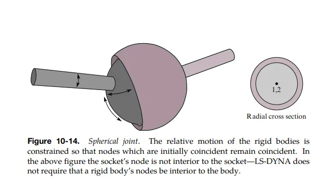
Case-1: SPherical Joint Between Rigid Bodies:-
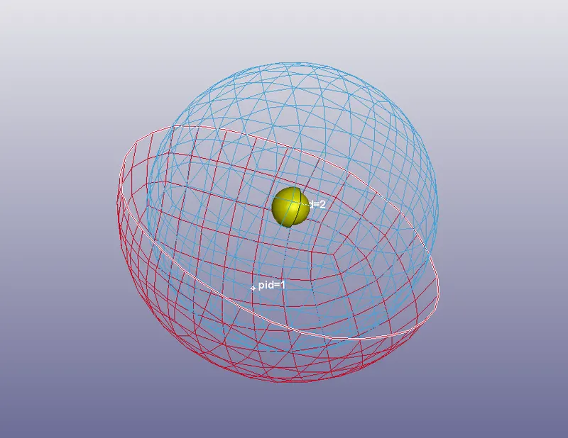
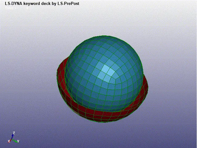
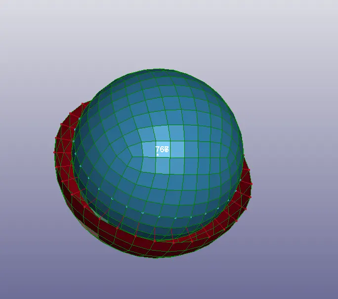
1.Create 2 shell Sphere by Mesh > Shape Mesher > Sphere Shell
2.Create 2 Shell sphere with 2 Different Radius and one Sphere Is trimmed half
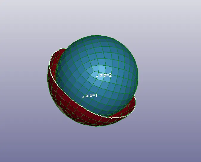
3. Create 2 nodes at the center and assign each node to belong to each part Individually
Constrained Extra_Node:
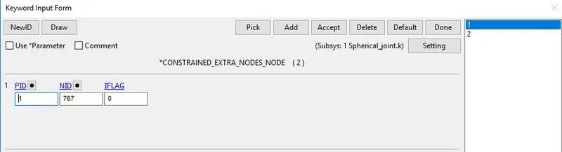
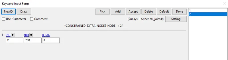
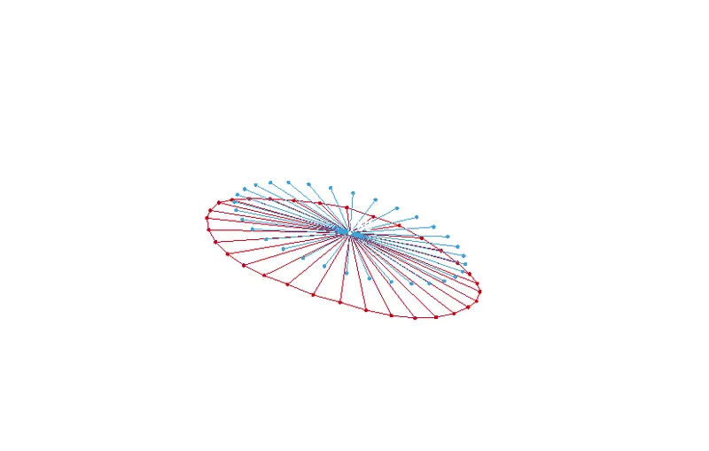
1.Two Nodes are created at the center 767,768 using Node edit > create with Coordinates (0,0,0)
2.Node 767 is assigned to the Outer sphere and Node 768 is Assigned to the inner sphere
Constrained Joint Spherical:-
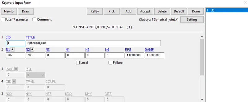
Constrained_Joint_Spherical card is assigned with the coinciding Node Id
Material:-
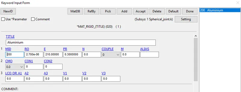
MAT_RIGID is Assigned with the Properties of Aluminium
Initial Velocity:-
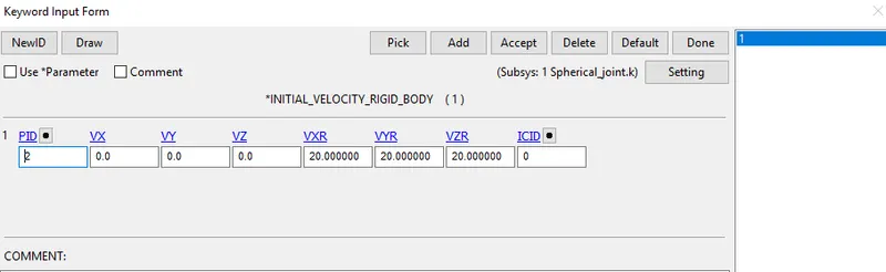
Initial Velocity is assigned to the Inner Sphere By INITIAL_Velocity_RIGID_BODY, with rotational velocities in the X, Y, Z axis.
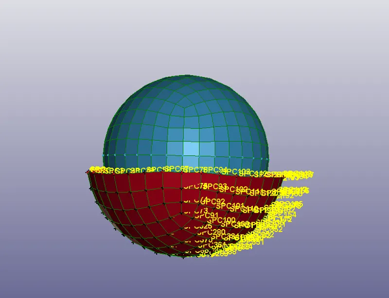
The Outer Sphere Is Constrained In All DOF's
All other keywords are Assigned as same in the Previous One
Case-2: SPherical Joint Between Deformable Bodies:-
1. Constraint Nodal Rigid Body is created for the Two Parts considering The Nodes 768,767 as of the origin
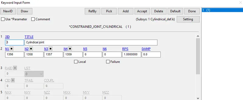
2. Constrained Joint Cylindrical card is defined with the Coinciding nodes
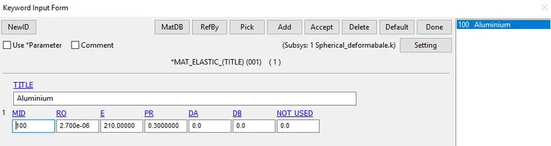
3.MAT_ELASTIC card is defined with the Properties Of Aluminum
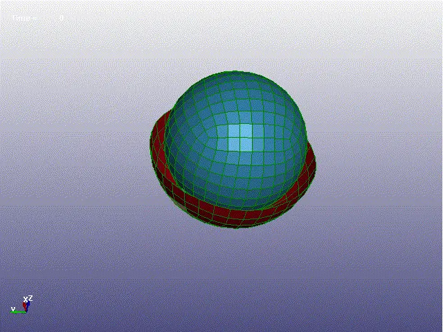
All Other Keywords And Cards remains Unchanged and the Simulation is executed
CYLINDRICAL JOINT:-
A cylindrical joint is Two degrees of Freedom Kinetic Pair used in mechanisms. Cylindrical joints provide a single-axis sliding function as well as a single axis rotation, providing a way for two rigid bodies to translate and rotate freely. This can be pictured by an unsecured axle mounted on a chassis, as it may freely rotate and translate.
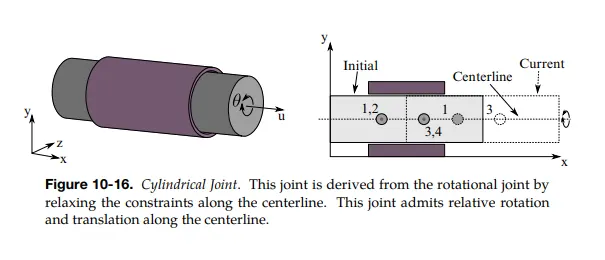
Case-1: Cylindrical Joint Between Rigid Bodies:-
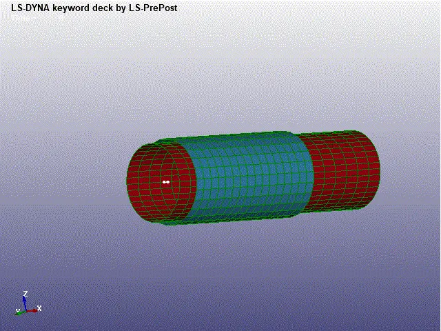
1.Create 2 Cylindrical Sphere by Mesh > Shape Mesher > Cylinder Shell
2.Create 2 Cylinder Shell with 2 Different Length and Radius
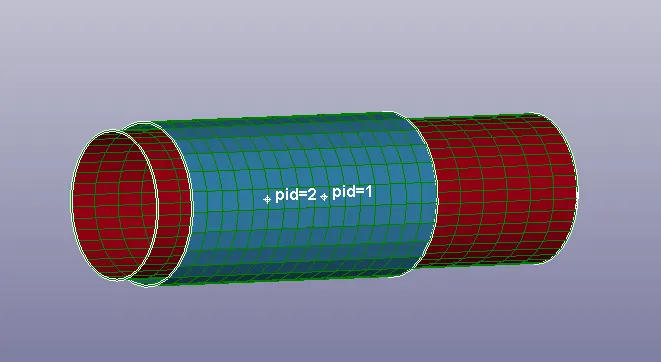
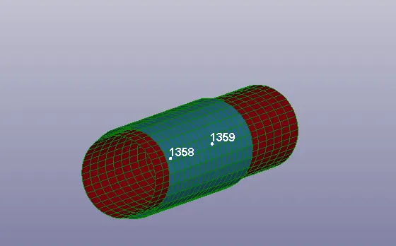
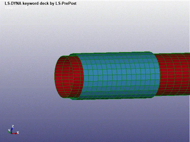
3.Two Cylinders Were Created With the Radius Of 10 and 11 mm of different lengths and Assigned as Part-1 and 2
Procedure:-
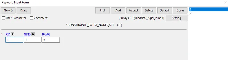
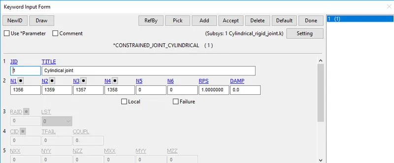
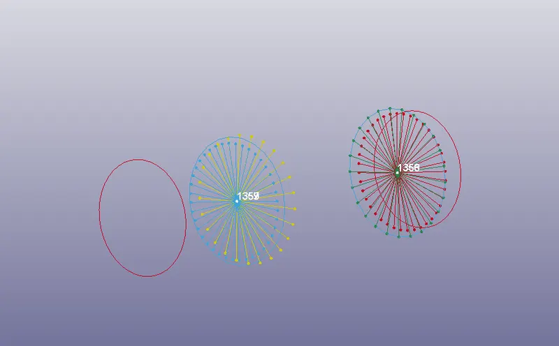
1. Create 2 Nodes at the Centre Node id= 1356, 1357 and Node set is created with These nodes and assigned to the part-1 cylinder with radius 10
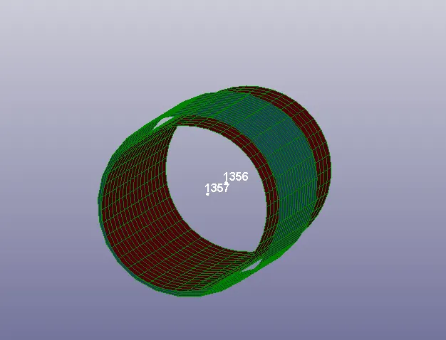
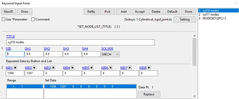
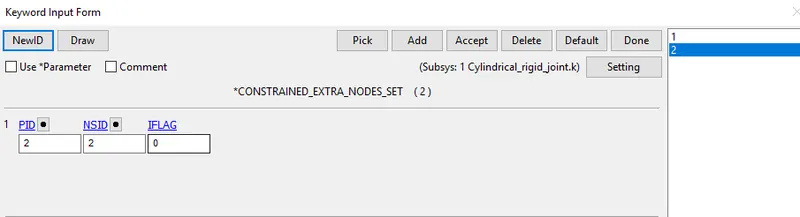
2. Create Another 2 Nodes Node id=1359, 1358 and Node set is created with These nodes and assigned to the part-2 cylinder with radius 11
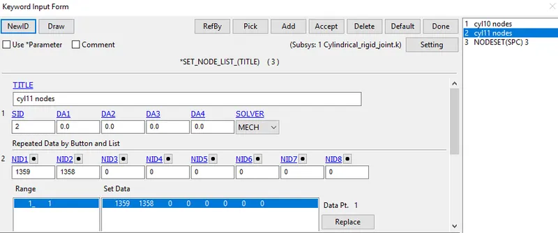
Constrained Extra Node Set:-
Constrained Joint Cylindrical:-
Constrained Joint Cylindrical Is defined with the Coinciding Nodes
Material:-
MAT_RIGID is Assigned with the Properties of Aluminium
Initial Velocity:-
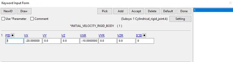
Initial Velocity is assigned to the Inner Cylinder By INITIAL_Velocity_RIGID_BODY, with rotational velocities in the X, Y, Z-axis along with the Translational Velocity in X axis
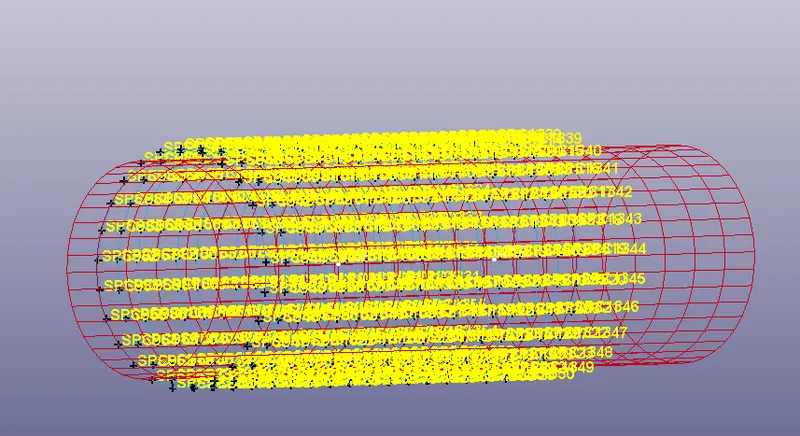
The Outer Cylinder Is Constrained In All DOF's
All other keywords are Assigned as same in the Previous One
Results:-
Case-2: Cylindrical joint Between Deformable Bodies:-
1. Nodal Rigid body Is created For two Cylinder Shells Considering the Coinciding nodes as the origin
2. Constrained Joint Cylindrical card is defined with the Coinciding nodes
3.MAT_ELASTIC card is defined with the Properties Of Aluminum
All Other Keywords And Cards remains Unchanged and the Simulation is executed
4.TRANSLATIONAL JOINTS:-
A translational joint allows one part to translate along a vector in respect of another part. The parts can only translate, not rotate, in respect of each other. This joint has one translational degree of freedom, and the rotational degree of freedom is 0. An axis of the translation is the z-axis.
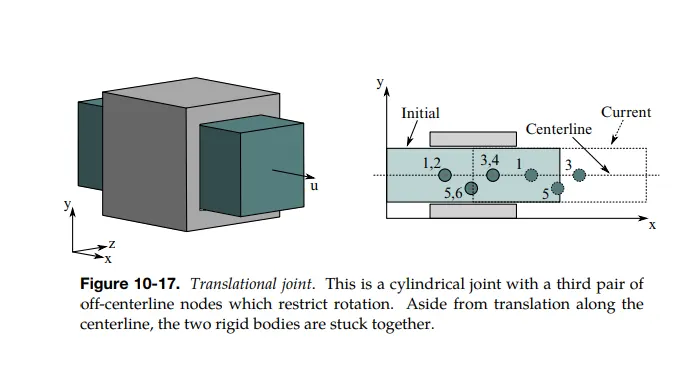
It is the same as the Cylindrical Joint but has an extra node that resits movement in rotational Axis
Case-1: Translational Joint Between Rigid Bodies:-
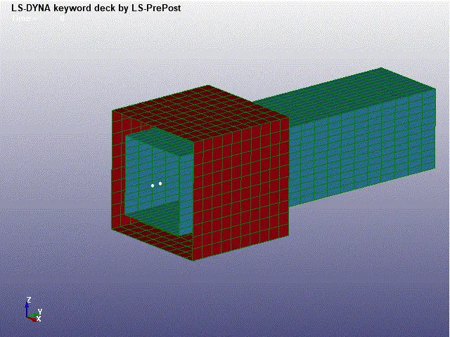
1. Create 2 Shell boxes of Different Heights and Length using Shape Mesher Option
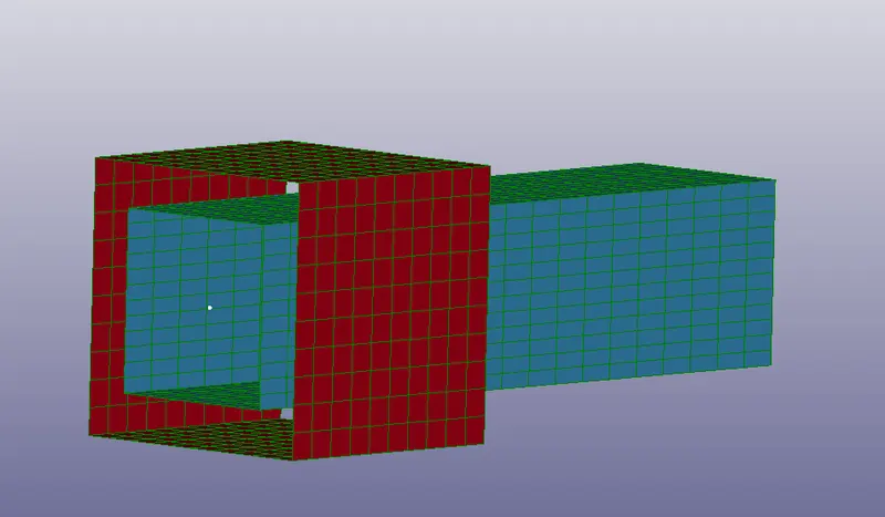
2. The 2 boxes are assigned as Part 1 and 2
Procedure:-
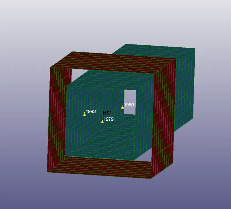
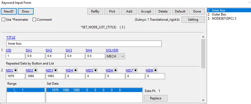
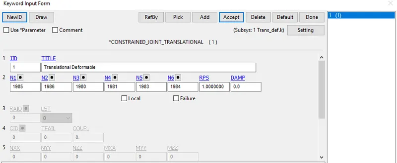
1. Create 2 Nodes at the Centre Node id= 1979, 1980 and a Node at the centre between these 2 nodes slightly deviated from the axis of the 2 nodes created and node id is noted as 1983, a Node set is created with These nodes and assigned to the part-1 Inner box
2. Create Another 2 Nodes at the Centre Node id= 1981, 1982 and a Node at the center between these 2 nodes slightly deviated from the axis of the 2 nodes created and node id is noted as 1984, a Node set is created with These nodes and assigned to the part-2 Outer box
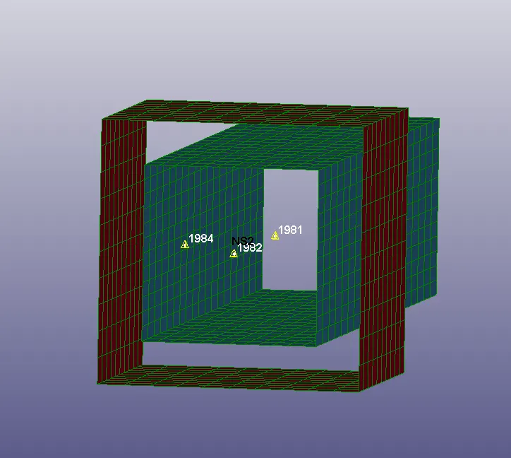
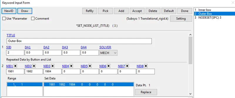
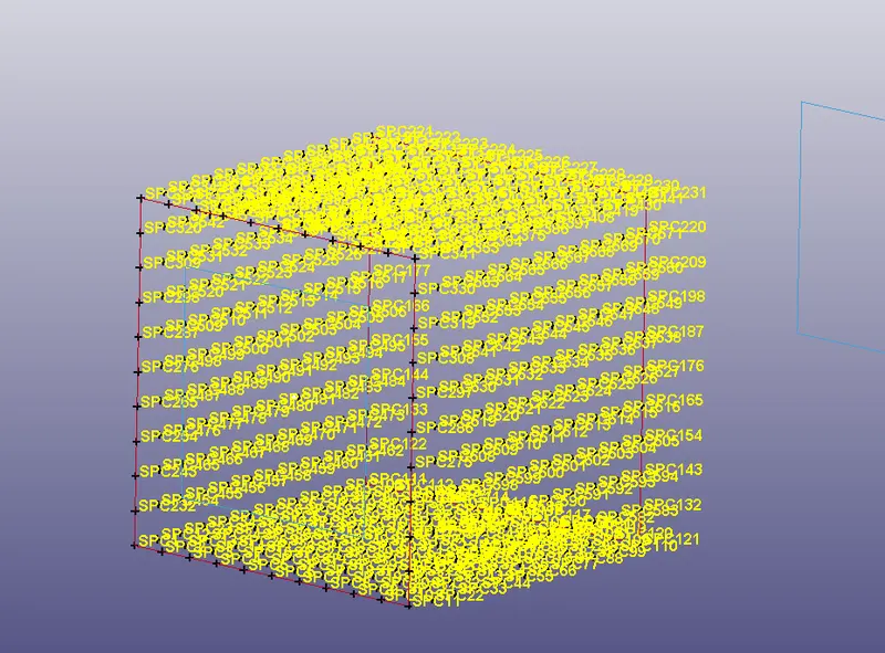
From the image, it's shown that These 6 nodes have coincided with each other
Constrained Extra Node Set:-
Constrained JointTranslational:-
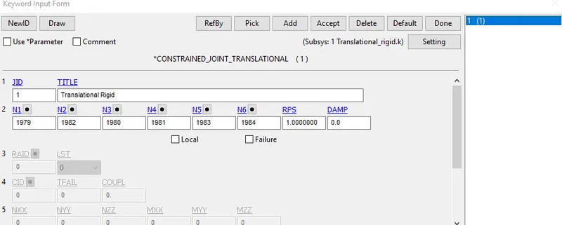
Constrained JointTranslational Is defined with the Coinciding Nodes
Material:-
MAT_RIGID is Assigned with the Properties of Aluminium
Initial Velocity:-
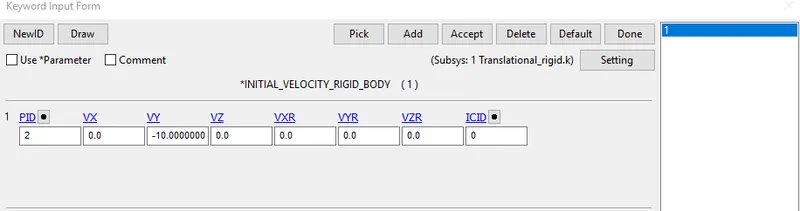
Initial Velocity is assigned to the Inner Box shell By INITIAL_Velocity_RIGID_BODY, with Translational Velocity in Y-axis
The Outer Box Is Constrained In All DOF's
All other keywords are Assigned as same in the Previous One
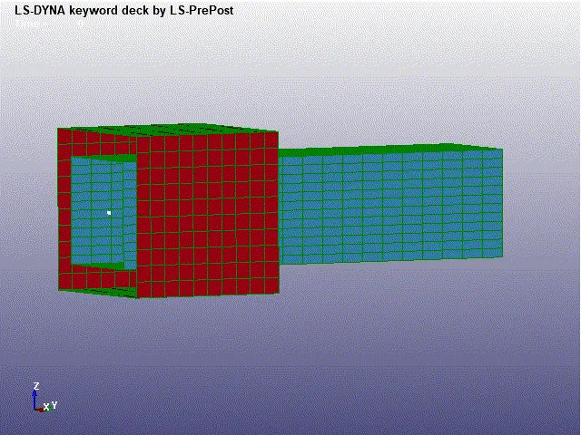
Case-2: Translational joint Between Deformable Bodies:-
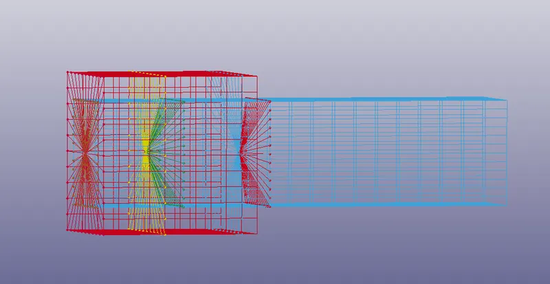
1. Nodal Rigid body Is created For two Box Shells Considering the Three Coinciding nodes as the origin, Therefore 6 nodal rigid Body is Created
2. CNRB is created by Turning of P-Node and By assigning respective Coinciding Nodes for each part
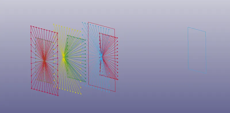
2. Constrained Joint Translational card is defined with the Coinciding nodes
3.MAT_ELASTIC card is defined with the Properties Of Aluminum
All Other Keywords And Cards remains Unchanged and the Simulation is executed
CONCLUSION:-
All the joints, Spherical, Revolute, Cylindrical, and Translational joints between two rigid bodies and two deformable bodies are demonstrated with the help of the Ls-Dyna manual (*CONSTRAINED_JOINT keyword,).