Week-7 Head Impact
Head Impact:
All units are taken in kg mm ms based on conversion factor of models imported.
Aim:
To determine the Pedestrian protection on the we look for imparting minimum injury to head, upper leg (thigh), and lower leg (including knee) in case of an accident with a human subject. These tests are usually done at a lower velocity from 20-40 kmph as accidents tend to result in more severe circumstances above these velocities and braking in case of an accident often results in collision at low velocities.
Steps followed:
Import the model for simple head,pedestrian head & Hood which is provided in the question in .k format.
At first we will take case 1 of the Simple Head model which is hollow for our case 1,then Pedestrian head for case 2 and for case 3 we have to take Meshed Hood,Pedestrian head both.
Case1:
Geometry & Meshing:
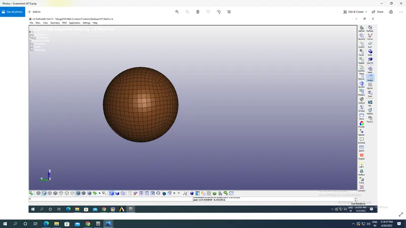
Imported model of simple head looks like shown in the image below which contains in it shell elements with hollow sphere as shown in the image below:
Section:
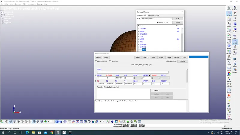
Now create section for sphere of skull which is hollow from inside and as we know for that we have to create a shell section of it with appropriate Element formulation of 2 which is Belytschko-Tsay membrane which is fully integrated & Ideal for fabrics with negligible bending stiffness and at the same time this formulation is economical. Shell thickness is taken as 1 mm as shown in the image below:
Material selection:
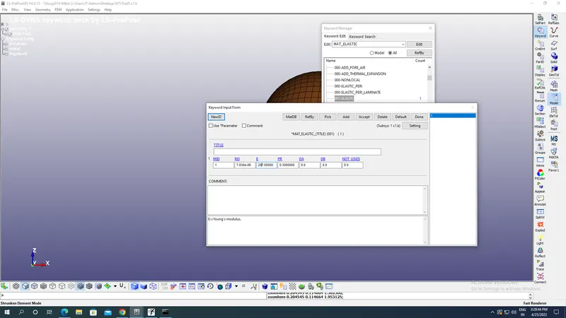
Now select the 001 Elastic material for sphere under Mat keyword by going into Toolbar at right containing Model and from there Keyword & from there to MAT-001N Elastic material.This 001 Elastic material is chosen with density of steel as 7.80E-06 kg/mm^3,Young’s Modulus as 207 kg mm^-1 ms^-2 & Poission’s ratio as 0.3 so that we can observe elastic deformation of sphere upon collision with rigid planar wall.
Parts creation:
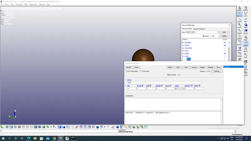
Now the parts which are there after Geometry are assigned with section &, material Id under Part option keyword by going into Toolbar at right containing Model and from there Keyword & from there to Part by assigning section id,material id,part id & Part title as shown in the image below:
Rigid wall:
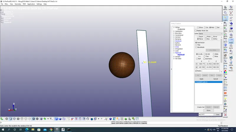
Now rigid wall of Planar format is created by going into Create entity option under Toolbar present under Model option present at the right side of screen with appropriate Tails & Heads of plane wall such that there is change of orientation of wall opposite to the velocity to be applied at the sphere by using Transform option which is here along positive X axis as velocity of skull must be along negative X axis here.
Boundary conditions:
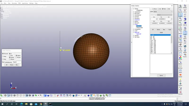
Now we have to apply initial velocity nodewise to the skull along the negative X & Z axis such that it resembles how a collision of the skull with Bonnet of a car happens after a person is hit by the car. We have taken here velocity as 6 mm/ms along negative X & along negative Z its 3mm/ms by selecting all nodes of sphere as shown in the image below:
Termination time:
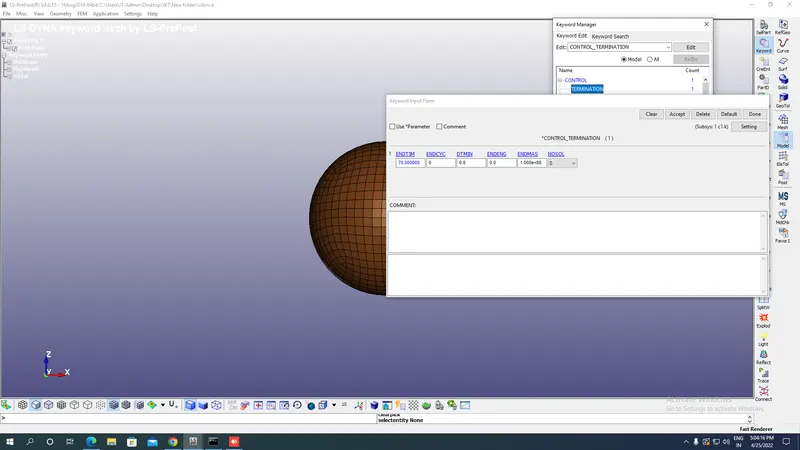
In order to stop the simulation the Termination End Time is given as shown in the image below which is a mandatory card found under Toolbar-Models-Keyword-Controls-Termination with End time as 70 ms applied here.
Outputs request:
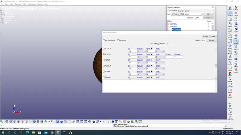
For results go to Database-ASCII define NODEOUT option for acceleration,HIC etc at the desired node as shown in the image below with DT as 10ms.
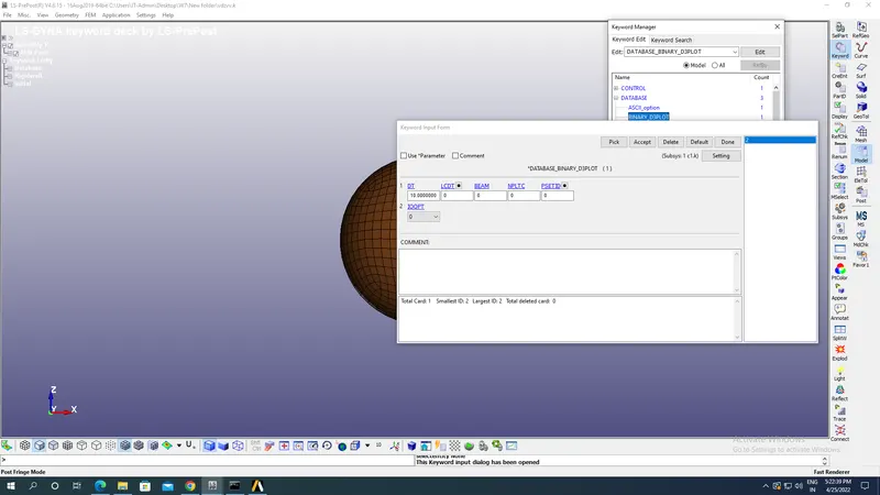
Now go to Binary 3D plot under database for animation and provide animation step(DT) as 10 ms as shown in the image below:
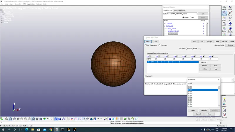
In order to have output at nodes go to Database select the History Nodes option & apply the node ID at which desired output of acceleration & HIC is required.
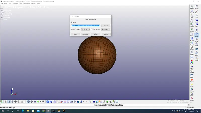
Now go to files & select Save as option under which select save keyword as option with appropriate name of folders & file created as shown in the image below:
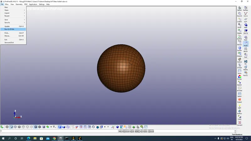
Now Run the LS dyna file under Run as LS Dyna option under files as shown in the image below:
Results:
Binary D3 plots:
Von mises stress plot:
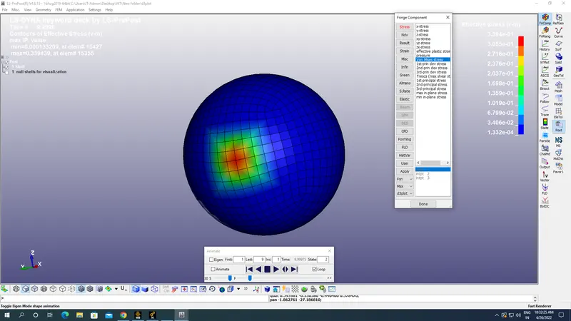
Maximum Von mises stress:3.394E-01 kg mm^-1 ms^-2.
Von mises Strain plot:
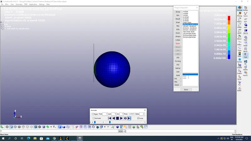
Maximum Von mises strain:9.806E-09.
ASCII Plots:
We have selected a Nodeout in ASCII option with animation step(DT) as 10 ms & History node with Node IDs for desired results at a particular node in the skull.
Resultant acceleration plot at Node id 68790:
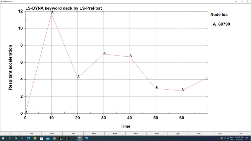
Maximum resultant acceleration at node :11.7 mm/ms^2.
Head Injury Coefficient/Criteria AT 36 ms(HIC-26):
HIC is quantification of head injury during collision of skull at time of retardation less than 36 ms.It is not the value which defines head injury but it is used by Abbreviated Injury Scale(AIS) to decide the various levels of injuries which skull receives at a particular HIC values.Example HIC value of 650 means 90% of level one,55% of level 2, 20% of level 3 & 5% of level 4.
Level 1:Slight damage to brain with Headache & Dizziness with no loss in consciousness.
Level 2:Concussion with or without skull fracture,less than 15 minutes of unconsciousness,detached retina,face and nose fracture.
Level 3:Concussion with or without skull fracture,more than 15 minutes of unconsciousness,without severe neurological damage,multiple skull fractures,loss of vision
Level 4:Multiple skull fractures with severe neurological damage.
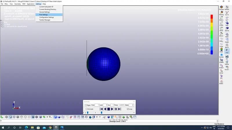
Before plotting HIC 36 we have to go to the Settings-Post setting option and change the unit of time as msec & gravity as 0.00981 mm/ms^2.
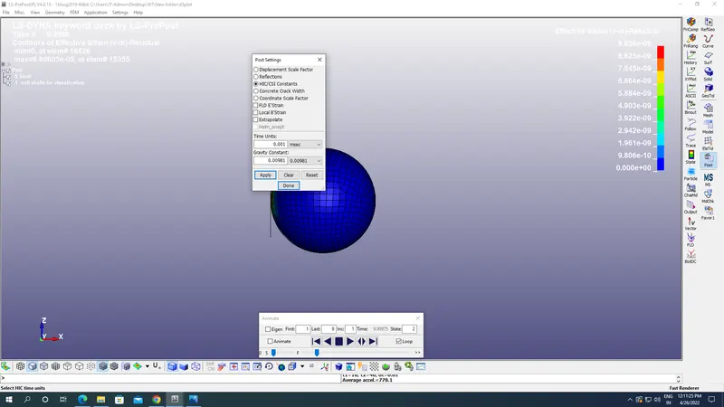
HIC 36 plot:
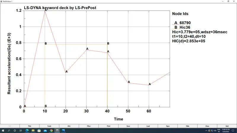
Maximum HIC observed :3.779E+05 at 36 msec with t1=10msec,t2=40 msec.
Case 2:
Aim: To rotate a Pedestrian Head about Y axis and collide with planar rigid wall and study its impact results.
Steps followed:
- First open the imported model of Pedestrian skull and decide about which axis we want to rotate the skull.The imported model appears as:
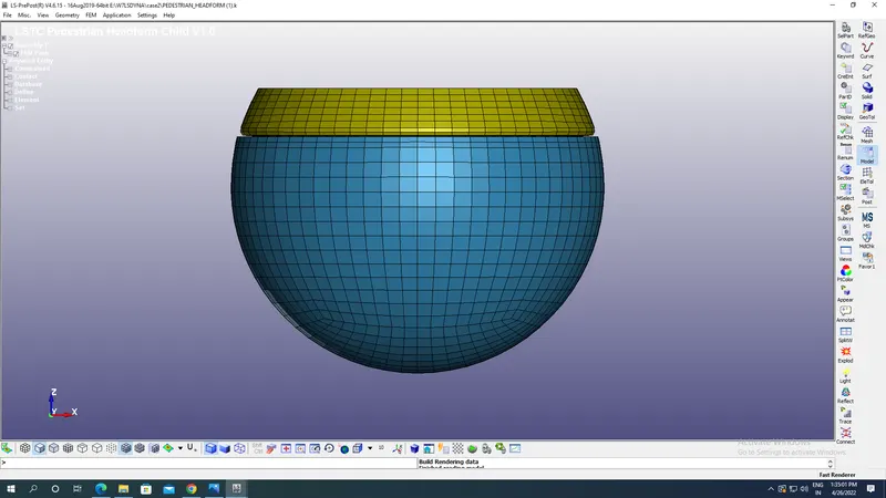
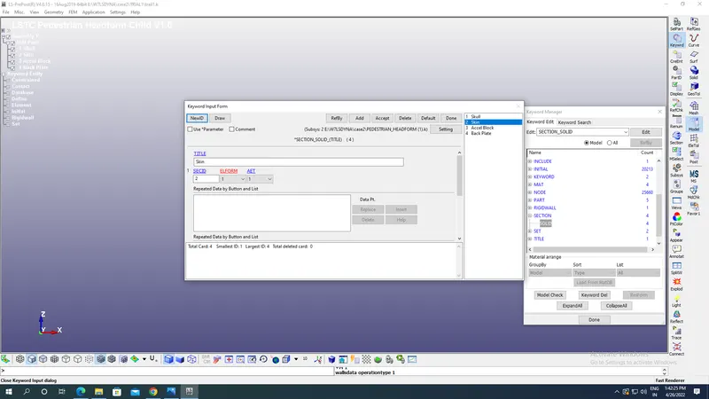
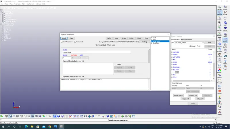
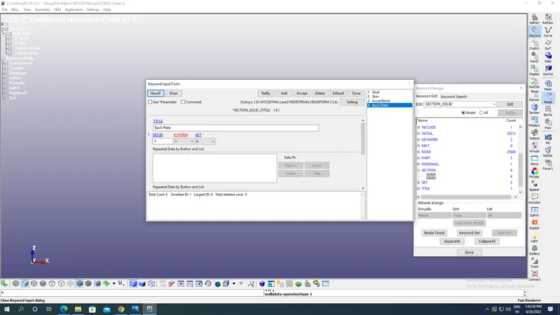
- Imported model above contains four parts which are skull,skin,acceleration block & back plate with solid section for each with Element formulation of 1 for constant stress solid element with different Section Ids as shown in the image below:
Section for skull:
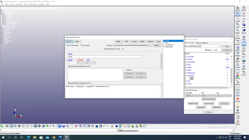
Section for skin:
Section for acceleration block:
Section for back plate:
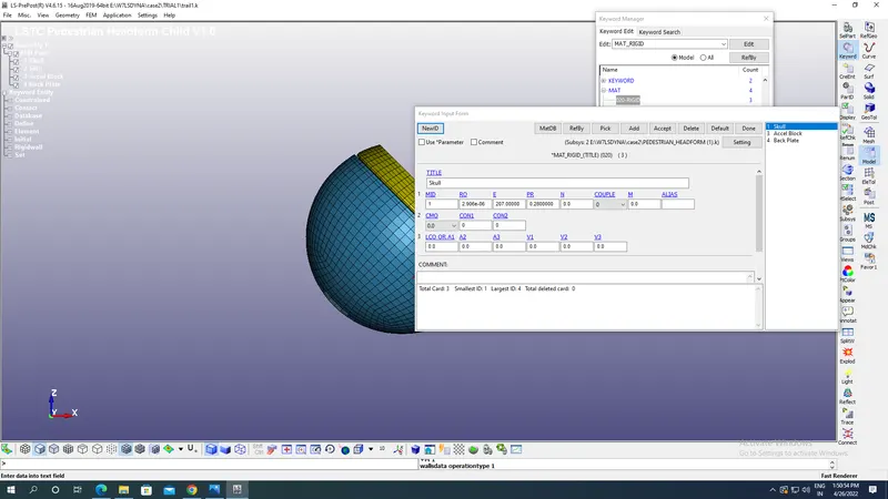
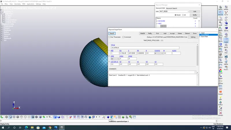
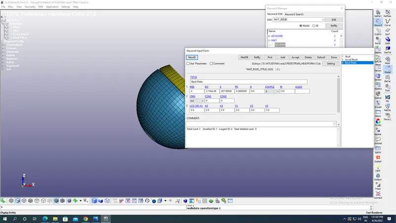
- Now we are going to define material used for entire skull assembly which are here MAT-020 Rigid for Skull,Acceleration block & Back plate with density as 2.906E-06 kg/mm^3,Young’s modulus as 207 kg mm^-1 ms^-2 and Poisson’s ratio as 0.28 with appropriate material ids.
Skull:
Acceleration block:
Back plate:
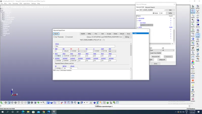
- Now MAT 077_O_OGDEN RUBBER material is used for skin of skull with various parameters as shown in the image below:
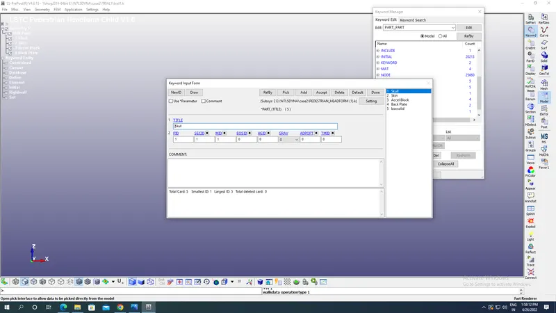
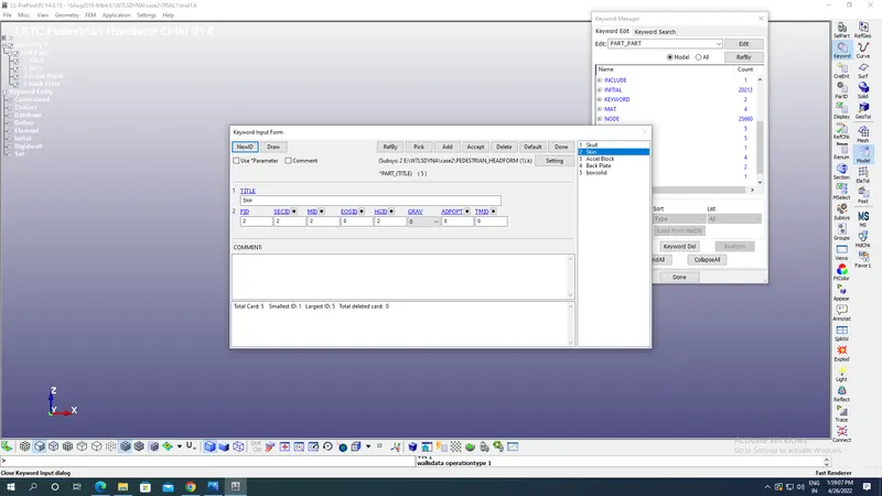
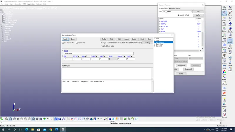
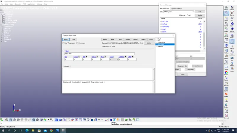
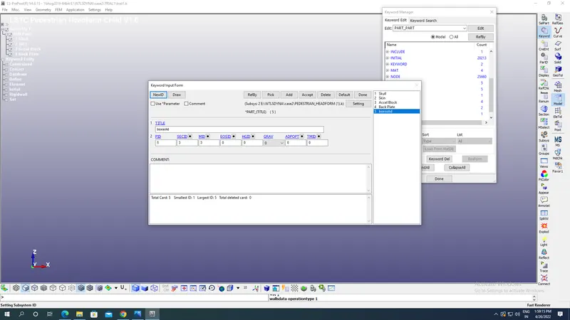
- Now we go to part keyword and assign material ID section ID to the parts with appropriate Title & part ID s to various parts as shown in the image below:
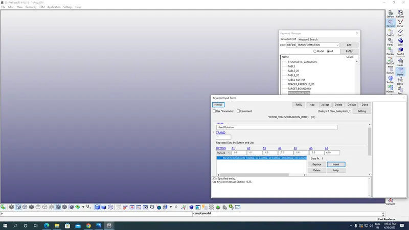
- Then we have to rotate the model of Pedestrian head form for that we will open new LS Prepost window and creating Define-Transformation option under Models-Keyword option with direction cosines of any line parallel to axis of rotation which is Y axis here it is 0,1,0 along x,y &z axis.Coordinates of line being parallel to Y axis which is here 0,0,0 with rotation angle being 45 degrees about line parallel to Y axis.Create appropriate Tran ID which is to be used in future.
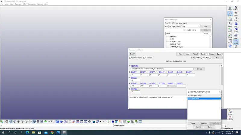
- Now go to Include-Transformation under keyword option select the file which you want to rotate which here is Pedestrian Head and after that we assign TRAN ID which was created before as shown in the image below:
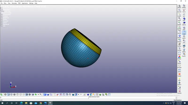
- Now save this model under File-Save-Save keyword as option & close this file.
- Open the new LS Prepost window and under file open the keyword file which was saved before the new roasted pedestrian skull appears as shown in the image below:
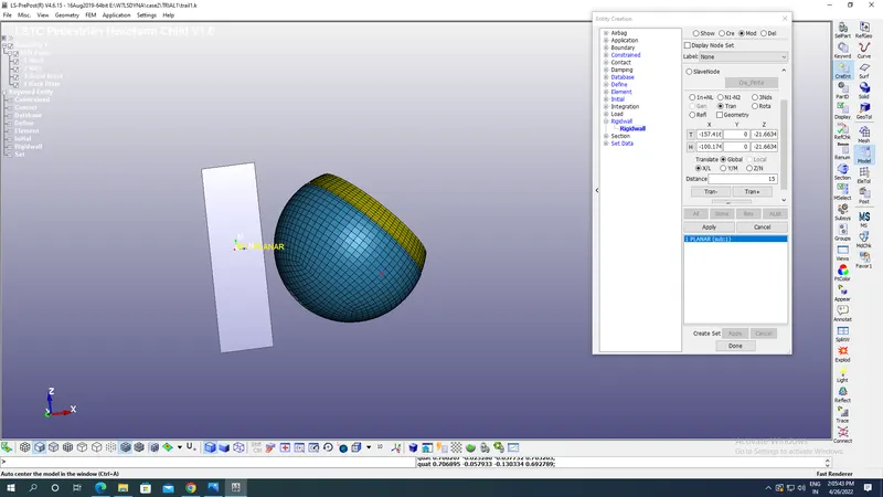
- Rigid wall:
Now rigid wall of Planar format is created by going into Create entity option under Toolbar present under Model option present at the right side of screen with appropriate Tails & Heads of plane wall such that there is change of orientation of wall opposite to the velocity to be applied at the sphere by using Transform option which is here along positive X axis as velocity of skull must be along negative X axis here.
- Boundary conditions:
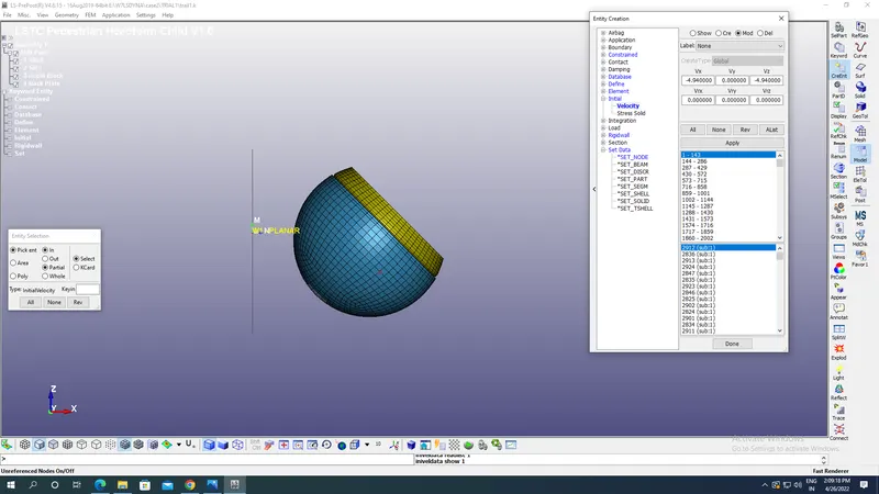
Now we have to apply initial velocity nodewise to the skull along the negative X & Z axis such that it resembles how a collision of the skull with Bonnet of a car happens after a person is hit by the car. We have taken here velocity as4.94 mm/ms along negative X & along negative Z its 4.94 mm/ms by selecting all nodes of sphere as shown in the image below:
- Termination time:
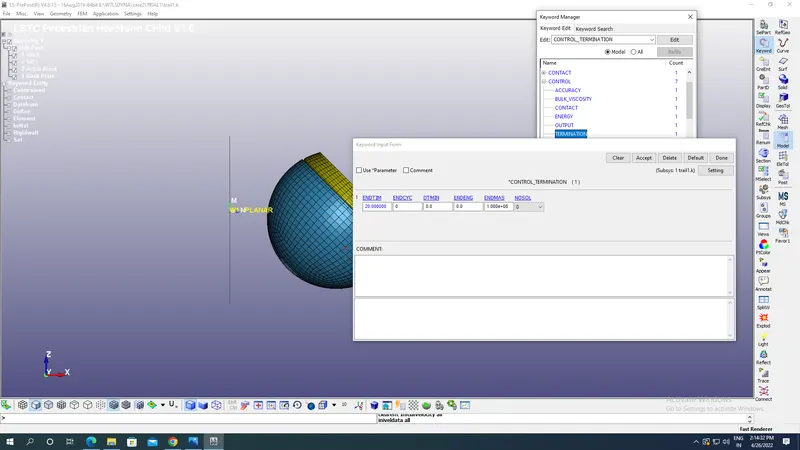
In order to stop the simulation the Termination End Time is given as shown in the image below which is a mandatory card found under Toolbar-Models-Keyword-Controls-Termination with End time as 20 ms applied here.
- Outputs request:
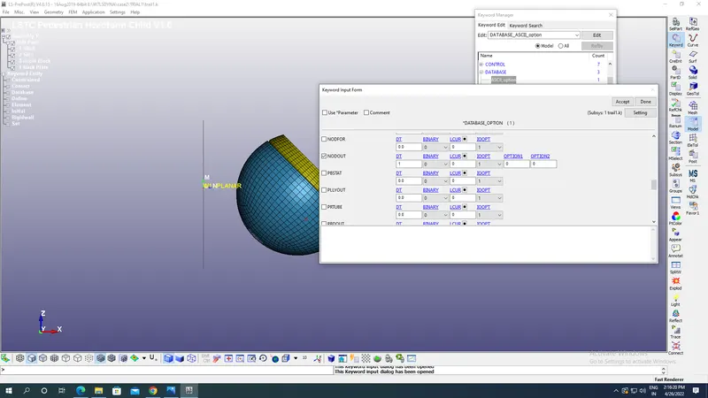
For results go to Database-ASCII define NODEOUT option for acceleration,HIC etc at the desired node as shown in the image below with DT as 1ms.
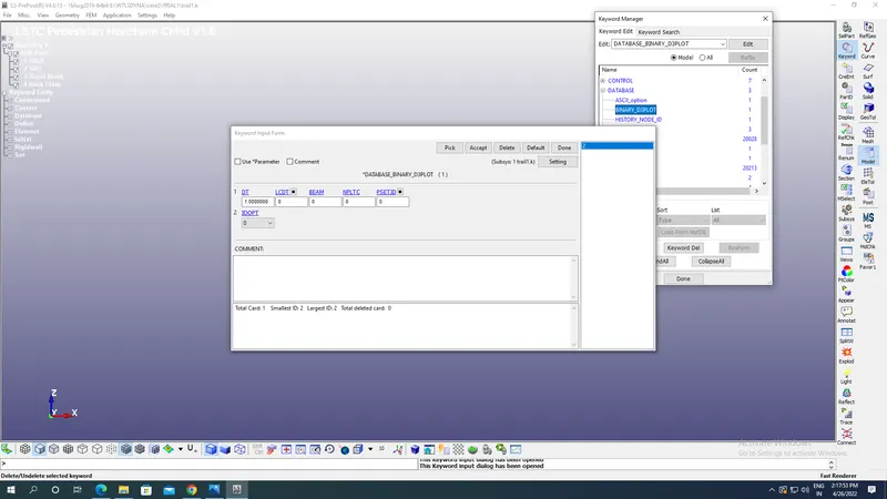
- Now go to Binary 3D plot under database for animation and provide animation step(DT) as 1 ms as shown in the image below:
- In order to have output at nodes go to Database select the History Nodes option & apply the node ID at which desired output of acceleration & HIC is required.
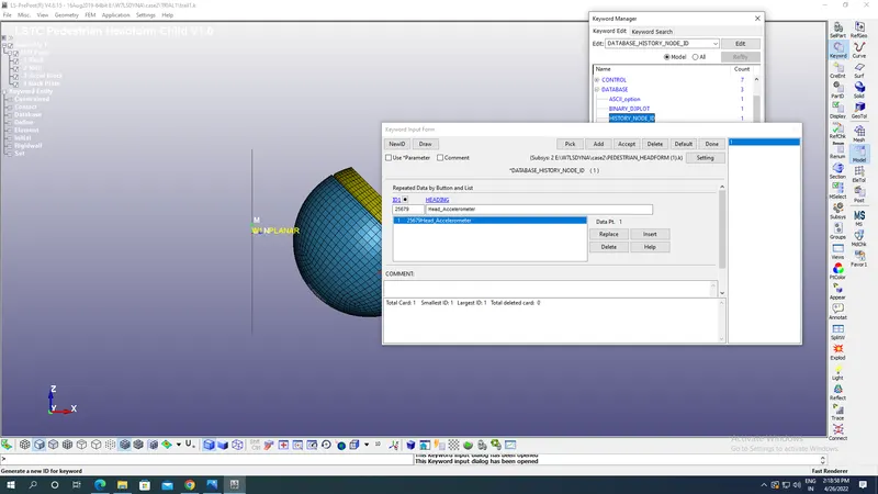
Now go to files & select Save as option under which select save keyword as option with appropriate name of folders & file created as shown in the image below
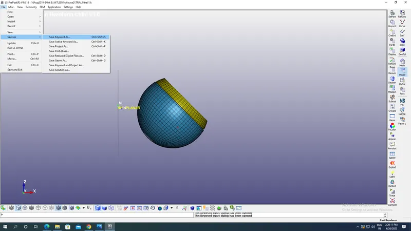
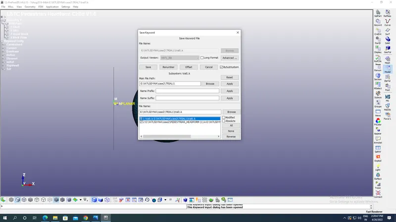
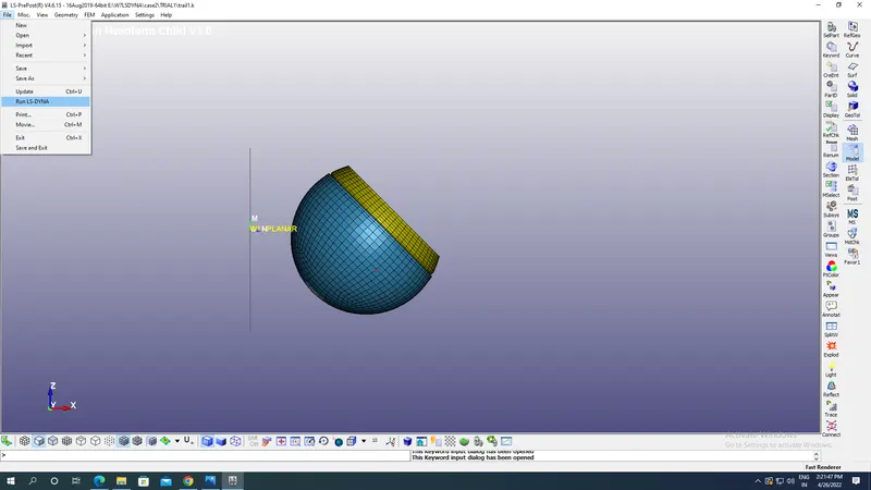
- Now Run the LS dyna file under Run as LS Dyna option under files as shown in the image below:
Results:
Binary D3 plots:
Von mises stress plot:
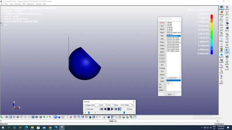
Maximum Von mises stress:4.563E-03 kg mm^-1 ms^-2.
Von mises Strain plot:
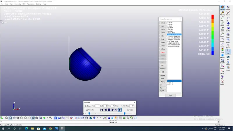
Maximum Von mises strain:1.318E-10.
ASCII Plots:
We have selected a Nodeout in ASCII option with animation step(DT) as 10 ms & History node with Node IDs for desired results at a particular node in the skull.
Resultant acceleration plot at Node id 25679:
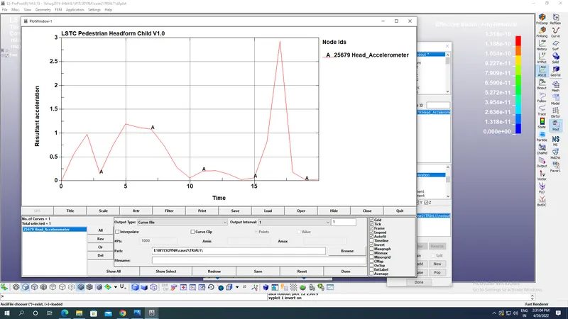
Maximum resultant acceleration at node :2.93 mm/ms^2.
Head Injury Coefficient/Criteria AT 36 ms(HIC-26):
HIC is quantification of head injury during collision of skull at time of retardation less than 36 ms.It is not the value which defines head injury but it is used by Abbreviated Injury Scale(AIS) to decide the various levels of injuries which skull receives at a particular HIC values.Example HIC value of 650 means 90% of level one,55% of level 2, 20% of level 3 & 5% of level 4.
Level 1:Slight damage to brain with Headache & Dizziness with no loss in consciousness.
Level 2:Concussion with or without skull fracture,less than 15 minutes of unconsciousness,detached retina,face and nose fracture.
Level 3:Concussion with or without skull fracture,more than 15 minutes of unconsciousness,without severe neurological damage,multiple skull fractures,loss of vision
Level 4:Multiple skull fractures with severe neurological damage.
Before plotting HIC 36 we have to go to the Settings-Post setting option and change the unit of time as msec & gravity as 0.00981 mm/ms^2 like we did in case 1.
HIC 36 plot:
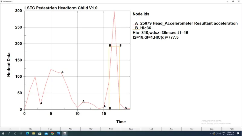
Maximum HIC observed :810 at 36 msec with t1=16msec,t2=18 msec.
Case 3:
Aim: To rotate a Pedestrian Head about Y axis and collide with Hood of car and study its impact results.
Steps followed:
- First open the imported model of Pedestrian skull and decide about which axis we want to rotate the skull.The imported model appears as:
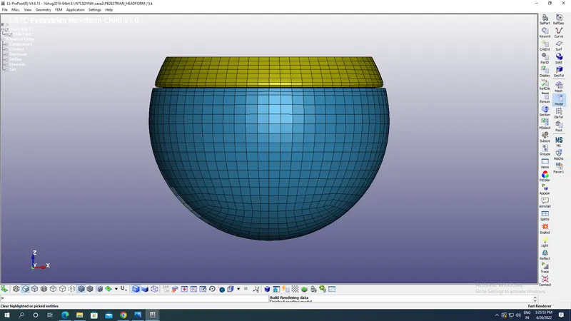
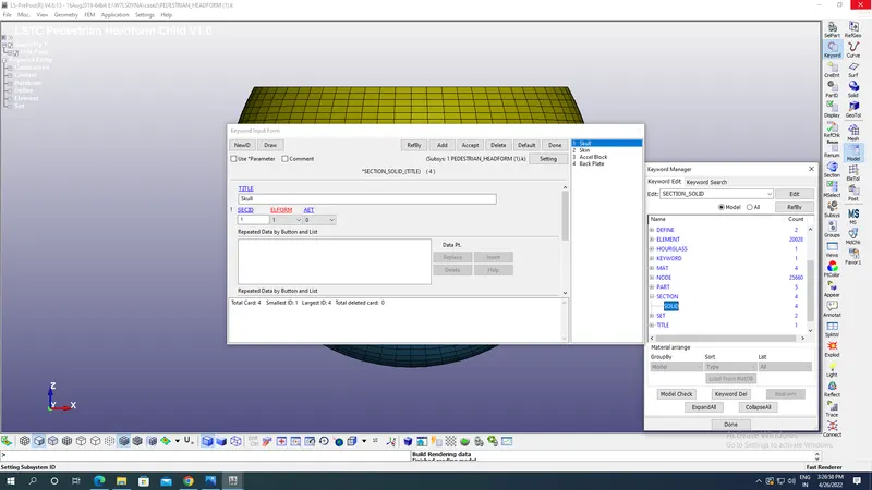
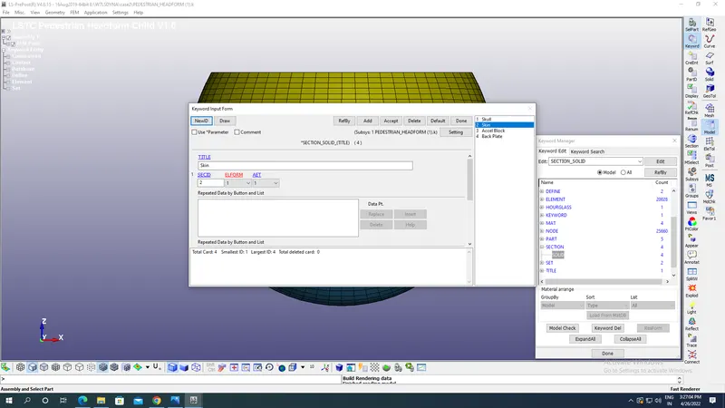
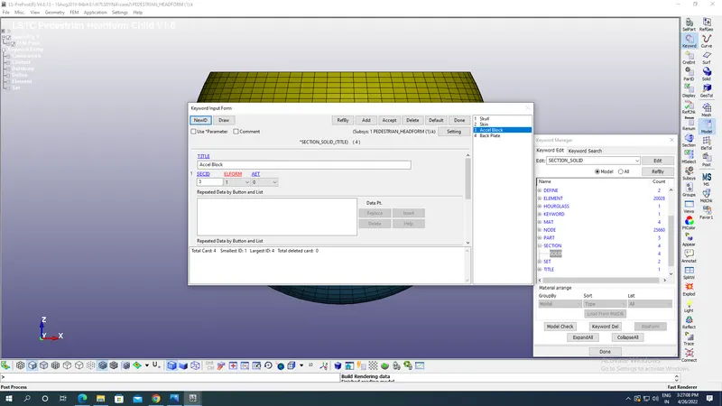
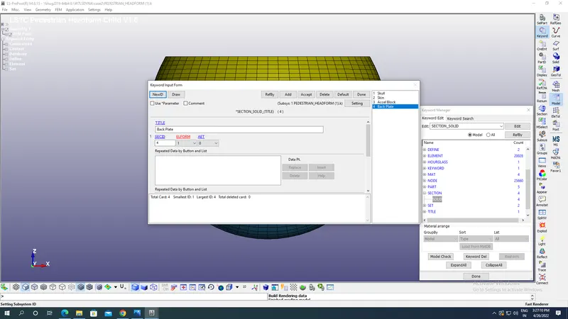
- Imported model above contains four parts which are skull,skin,acceleration block & back plate with solid section for each with Element formulation of 1 for constant stress solid element with different Section Ids as shown in the image below:
Section for skull:
Section for skin:
Section for Acceleration block:
Section for Back plate:
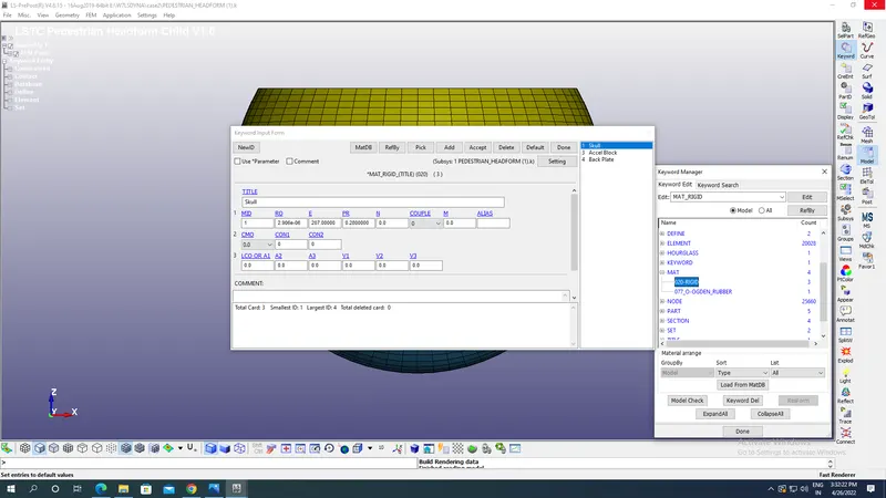
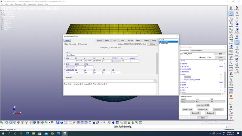
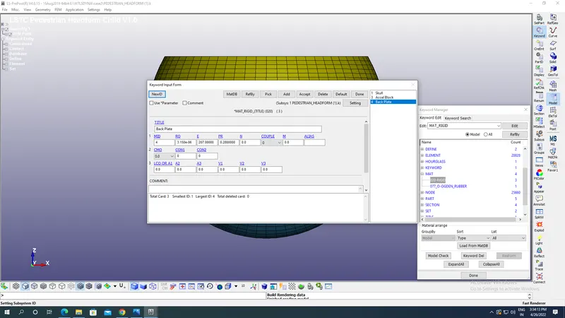
- Now we are going to define material used for entire skull assembly which are here MAT-020 Rigid for Skull,Acceleration block & Back plate with density as 2.906E-06 kg/mm^3,Young’s modulus as 207 kg mm^-1 ms^-2 and Poisson’s ratio as 0.28 with appropriate material ids.
Skull:
Acceleration block:
Back Plate:
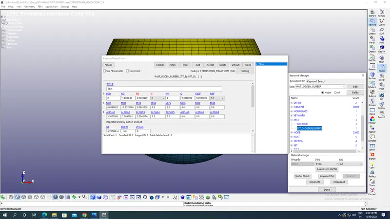
- Now MAT 077_O_OGDEN RUBBER material is used for skin of skull with various parameters as shown in the image below:
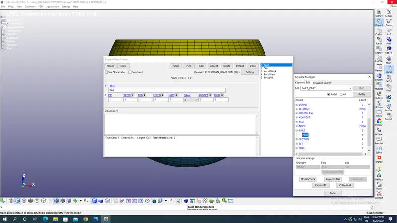
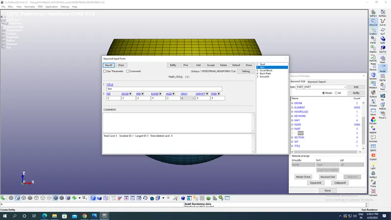
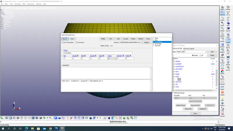
- Now we go to part keyword and assign material ID section ID to the parts with appropriate Title & part ID s to various parts as shown in the image below:
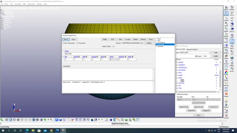
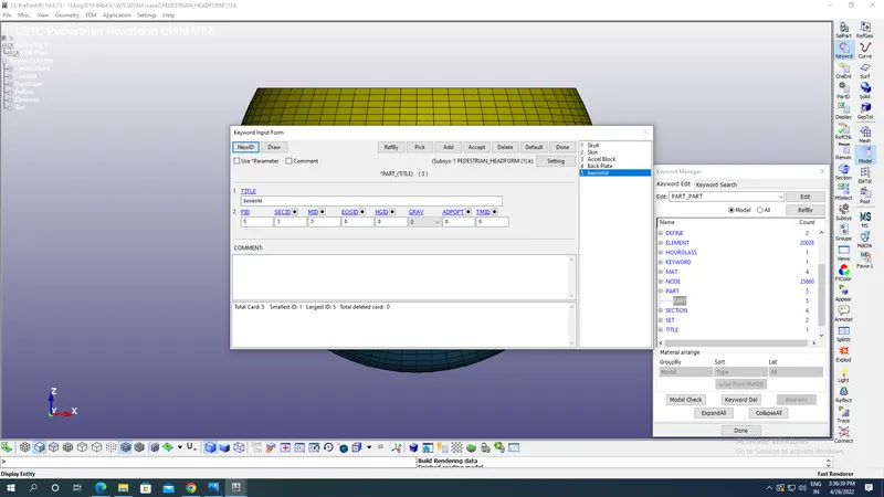
- Save the Pedestrian skull & open the imported model of Hood to create section & material for Hood.
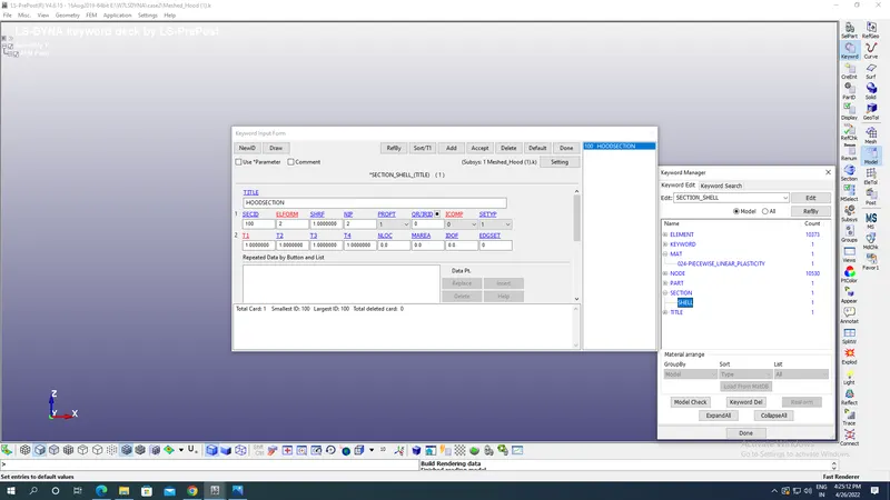
- Create a SHELL-section under section keyword option with 1mm thickness as shown in the image below with appropriate section ID:
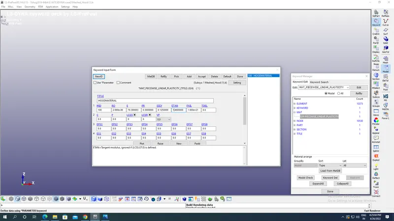
- Create a MAT 024 Piecewise linear plasticity with density,Young’s Modulus & poisson’s ratio of Aluminum as shown in the image below with appropriate material ID:
Now assign the section ID & material ID to the Part of hood created as shown in the image below:
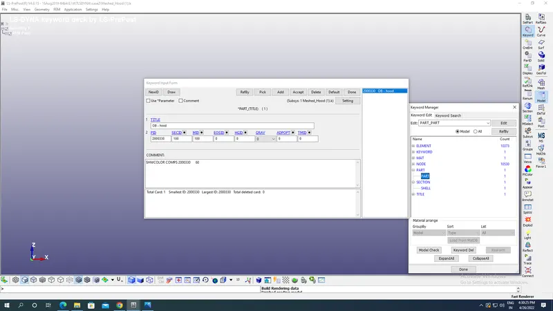
- Save the model like before in keyword format.
- Then we have to rotate the model of Pedestrian head form for that we will open new LS Prepost window and creating Define-Transformation option under Models-Keyword option with direction cosines of any line parallel to axis of rotation which is Y axis here it is 0,1,0 along x,y &z axis.Coordinates of line being parallel to Y axis which is here 0,0,0 with rotation angle being 45 degrees about line parallel to Y axis.Create appropriate Tran ID which is to be used in future same as case 2.
- Now we INCLUDE KEYWORD to include the Hood as shown in the image below under same LS Prepost option:
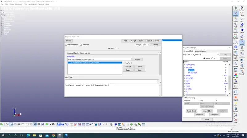
- Now go to Include-Transformation under keyword option select the file which you want to rotate which here is Pedestrian Head and after that we assign TRAN ID which was created before as shown in the image below:
- Now the file is saved to the desired location and open the keyword file in new LS Prepost which appears as shown in the image below:
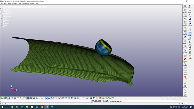
- Boundary conditions:
Now we have to apply initial velocity nodewise to the skull along the negative X & Z axis such that it resembles how a collision of the skull with Bonnet of a car happens after a person is hit by the car. We have taken here velocity as4.94 mm/ms along negative X & along negative Z its 4.94 mm/ms by selecting all nodes of sphere as shown in the image below:
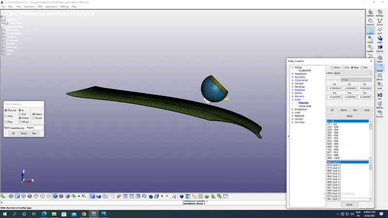
Create a Boundary SPC by fixing the boundary of hood as shown in the image below, we are not fixing Hood entirely because we have to check the stress & strains in hood.
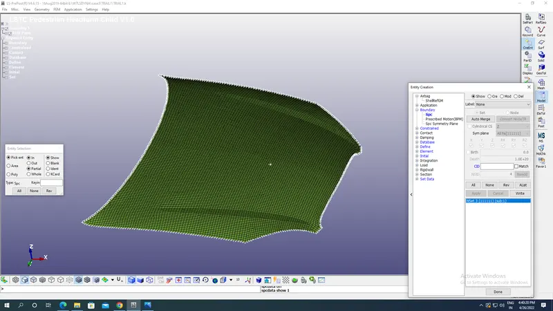
- Termination time:
In order to stop the simulation the Termination End Time is given as shown in the image below which is a mandatory card found under Toolbar-Models-Keyword-Controls-Termination with End time as 20 ms applied here.
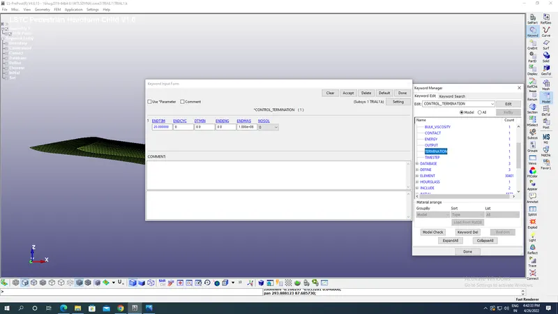
- Outputs request:
For results go to Database-ASCII define NODEOUT option for acceleration,HIC etc at the desired node as shown in the image below with DT as 1ms.
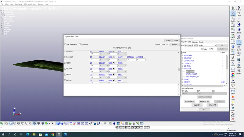
- Now go to Binary 3D plot under database for animation and provide animation step(DT) as 1 ms as shown in the image below:
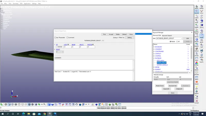
- In order to have output at nodes go to Database select the History Nodes option & apply the node ID at which desired output of acceleration & HIC is required.
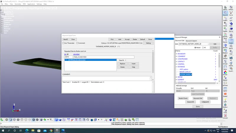
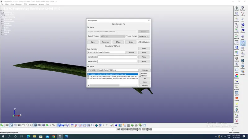
- Now go to files & select Save as option under which select save keyword as option with appropriate name of folders & file created as shown in the image below:
Results:
Binary D3 plots:
Von mises stress plot:
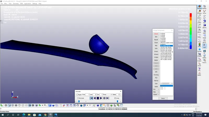
Maximum Von mises stress:9.756E-02 kg mm^-1 ms^-2.
Von mises Strain plot:
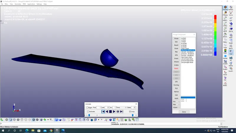
Maximum Von mises strain:2.818E-09.
ASCII Plots:
We have selected a Nodeout in ASCII option with animation step(DT) as 10 ms & History node with Node IDs for desired results at a particular node in the skull.
Resultant acceleration plot at Node id 25679:
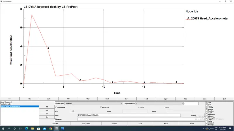
Maximum resultant acceleration at node :7.40 mm/ms^2.
Head Injury Coefficient/Criteria AT 36 ms(HIC-26):
HIC is quantification of head injury during collision of skull at time of retardation less than 36 ms.It is not the value which defines head injury but it is used by Abbreviated Injury Scale(AIS) to decide the various levels of injuries which skull receives at a particular HIC values.Example HIC value of 650 means 90% of level one,55% of level 2, 20% of level 3 & 5% of level 4.
Level 1:Slight damage to brain with Headache & Dizziness with no loss in consciousness.
Level 2:Concussion with or without skull fracture,less than 15 minutes of unconsciousness,detached retina,face and nose fracture.
Level 3:Concussion with or without skull fracture,more than 15 minutes of unconsciousness,without severe neurological damage,multiple skull fractures,loss of vision
Level 4:Multiple skull fractures with severe neurological damage.
Before plotting HIC 36 we have to go to the Settings-Post setting option and change the unit of time as msec & gravity as 0.00981 mm/ms^2 like we did in case 1.
HIC 36 plot:
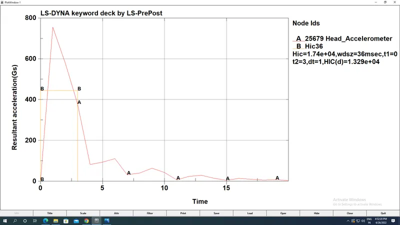
Maximum HIC observed :1.74E+04 at 36 msec with t1=0msec,t2=3 msec.
Comparison of case 1,2&3:
We can see from the images above that values of HIC value for case 2 is low compared to case 1&Case3 because of sliding of skull in Case2 when it's rotated and collided with rigid wall.At the same time we can see that actually the HIC value in case 3 is less than case 1 which is again due to infinite stiffness of rigid wall compared to Hood made up of Piecewise LInear Material 024. At the same time we can see that Von mises stress & strain is more in case 1 because of non siliding so no shear stress devloped while in case 2 & case 3 we have shear stress devloped due to sliding.Acceleration in case 1 is 11.7 mm/ms^2 which is higher than case 2& case 3.
Conclusion:
In all the three cases, the skull of Hollow & solid section is collided with rigid wall & Hood made up of Plastic material of 024 and stress,strain & HIC values are compared and results are plotted and compared as shown in the images above.