Week 7-Long Piston With Cam
Transient Analysis on Piston & Cam:
Aim: To perform transient analysis on Piston and Cam mechanism model with frictionless contact,frictional contact of given frictional coefficients of 0.1 and 0.2.
Steps followed:
1)Material Selection:
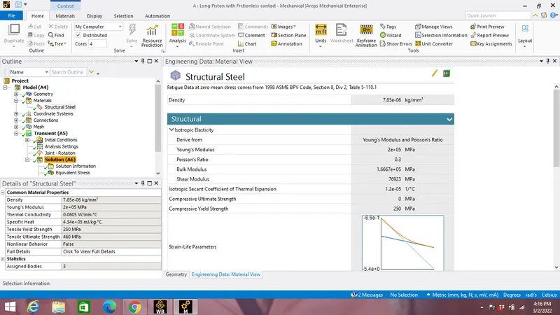
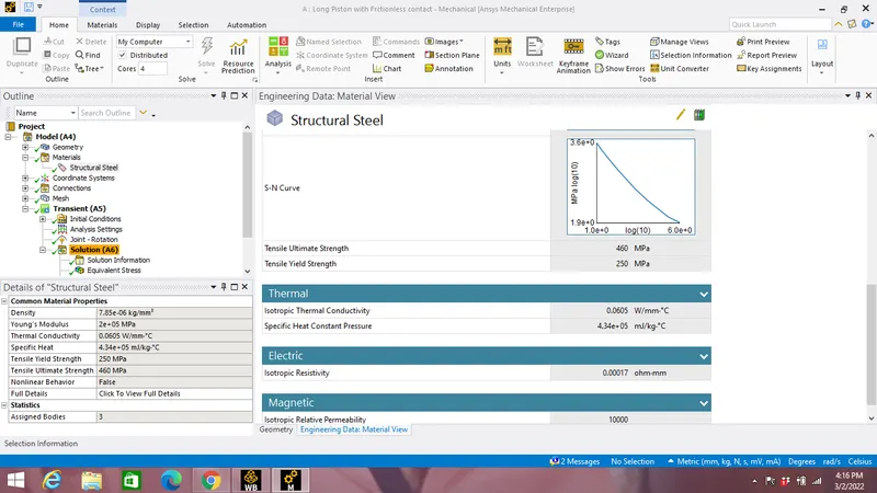
Structural steel is choosen as material for Barrel,Cam and its Follower with the material specification as listed below:
2)Geometry:
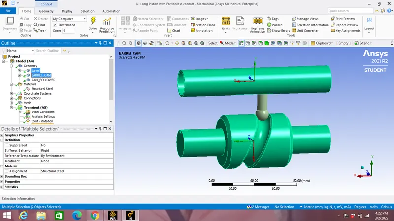
Required geometry of Barrel,Cam & its Follower is imported from the CAD file shared above and in Models parts are renamed as Barrel,Cam and Cam Follower with Rigid type of Stiffness to both Barrel & Cam as we want to do analysis of Follower only so we have to change Barrel & Cam to be rigid bodies with masses at the Centre of mass with no Stress,Strain or deformation acting on them.
3) Contacts & Joints:
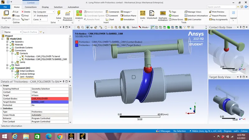
Select the Contacts in the Connections setting & select both the contacts by shift key and with Right click select Flip Contact/Target option to rename contacts.
Update the second contact option by selecting the faces shown below:
Case 1:
For the frictionless type of contact select both the contacts by the shift key & Type:Frictionless.
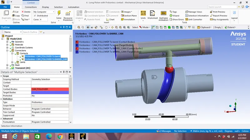
Case 2:
Select the faces of second contact option same as above only change Type:Frictional with Frictional Coefficients of 0.1 by selecting both the contacts with Shift key:
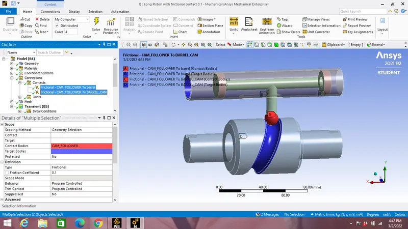
Case 3:
Select the faces of second contact option same as above only change Type:Frictional with Frictional Coefficients of 0.2 by selecting both the contacts with Shift key:
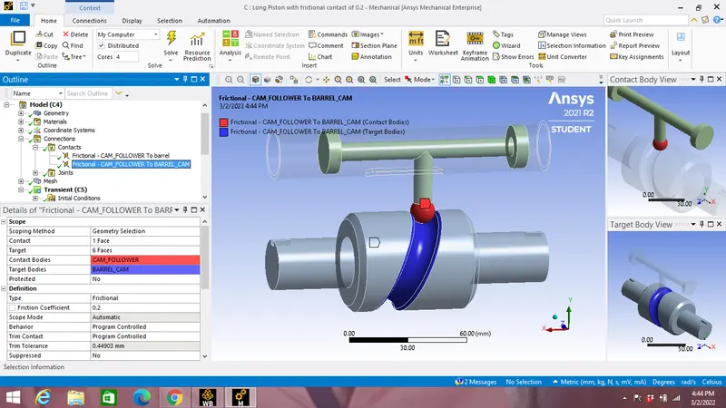
Joints:
Joints are same for all the above three cases.
a)Fixed Joint:
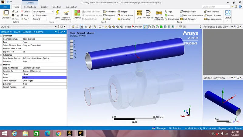
A fixed joint Body-Ground is applied by selecting the face of Barrel as it is fixed always with piston sliding inside it.
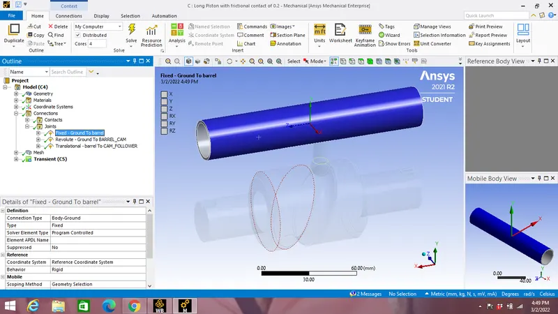
Fixed Joint settings are shown in the image below:
b)Revolute Joint:
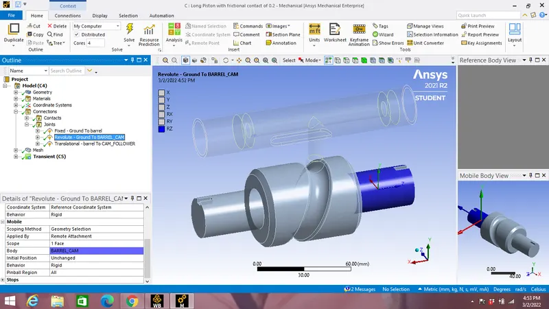
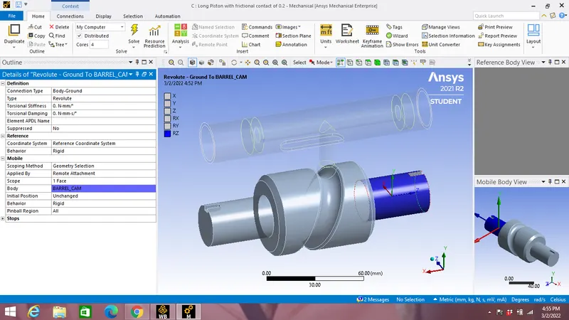
A Revolute Joint is given by selecting the one face of Cam with Connection Type:Body-Ground:
Revolute Joint settings are shown in the image below:
c)Translational Joint:
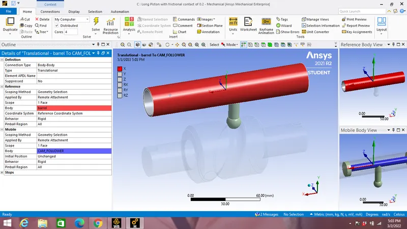
A Translational Joint is applied by selecting the face of Piston inside Barrel with Body-Body as Connection type by taking the Refrence body as Barrel and Mobile Body as Piston.
Mobile Body is applied by selecting curve face of piston as shown in the image shown below:
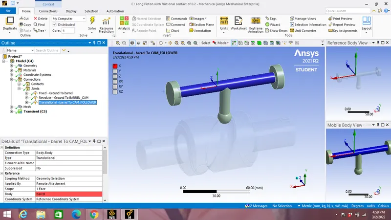
Reference body is selected as Barrel by selecting curve face of Barrel covering the Piston as shown below:
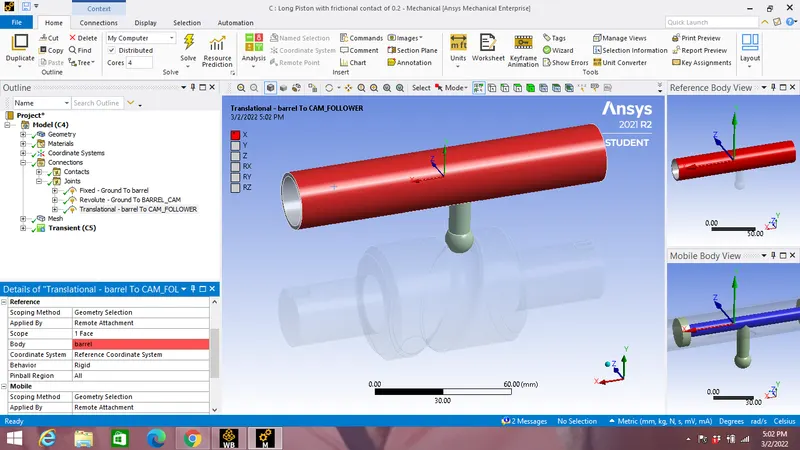
Translational Joint settings are shown in the image below:
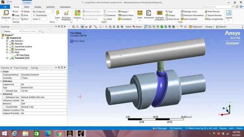
4)Meshing:
Meshing is doen by selecting the contact surface of Cam & Follower with element size of 3mm.
5)Boundary canditions:
For all the three cases mentioned above boundary canditions are kept same.
a)Analysis Setting:
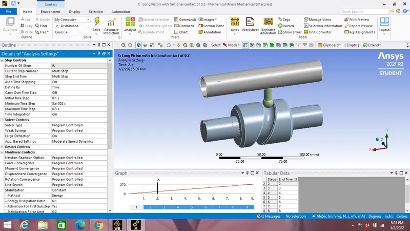
Number of steps for analysis is taken as 9 with Intial Time Step as 0.1,Minimum Time Step as 5e-002 and Maximum Time Step as 0.2. Weak Springs & Large Deflections are switched On.
Within Nonlinear Controls Stablization is taken as Constant with Energy Dissipation of 0.1 and Activation for the first substep is choosen Yes and all Output controls are selected Yes except Contact Miscellaneous as No.
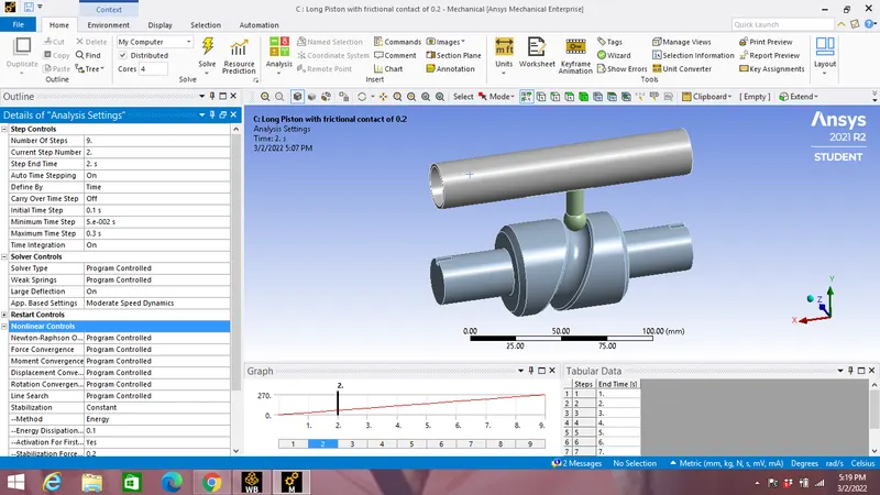
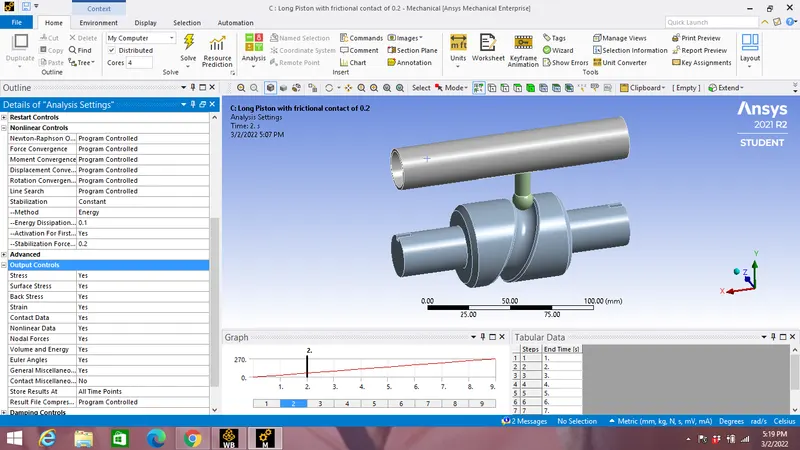
From steps 2 to 9 choosen with Shift key with intial time step as 0.1 s,minimum time step as 5e-002 s and maximum time step as 0.3 s. All other analysis setting of Nonlinear controls & output controls are kept same as that in step 1 above.
b)Joint Rotation:
Rotation is applied in tabular format with respect to Z axis by taking Revolute joint Ground to Barrel.
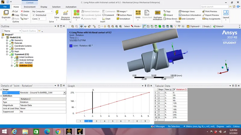
Rotation in Tabular format:
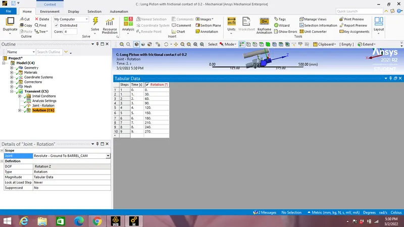
Rotation vs Step graph:
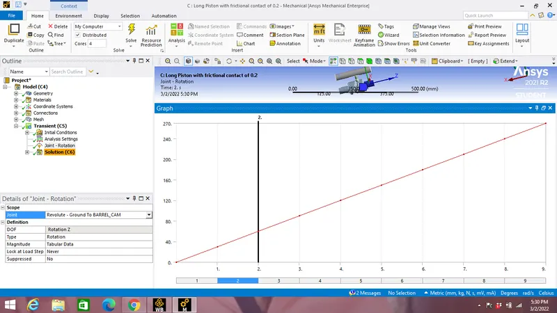
Results:
Case 1:
Frictionless contacts:
Equivalent Stress of Cam's Follower:
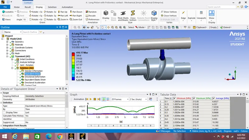
Stress vs Time graph:
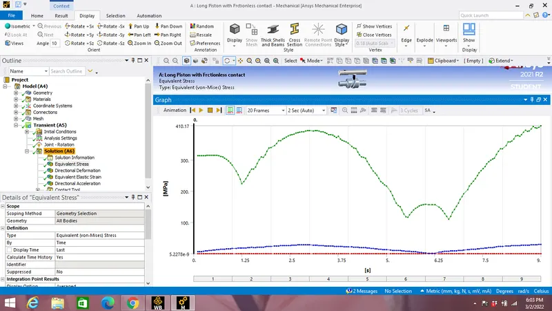
Maximum Equivalent Stress:410.17 MPa
Directional Deformation:
Directional deformation is taken along Z axis for the Follower as shown in the image below:
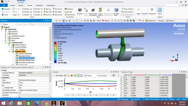
Maximum Directional deformation along Z axis:50.796 mm.
Equivalent Elastic Strain:
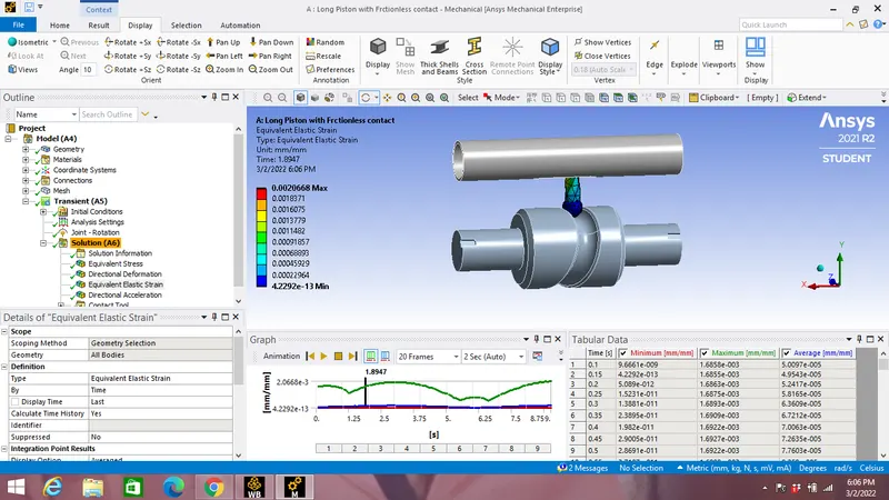
Equivalent Strain vs Time graph:
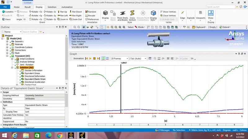
Maximum Equivalent Strain:2.0668e-3
Case 2:
Frictional contact with 0.1 frictional coefficients:
Equivalent Stress of Cam's Follower:
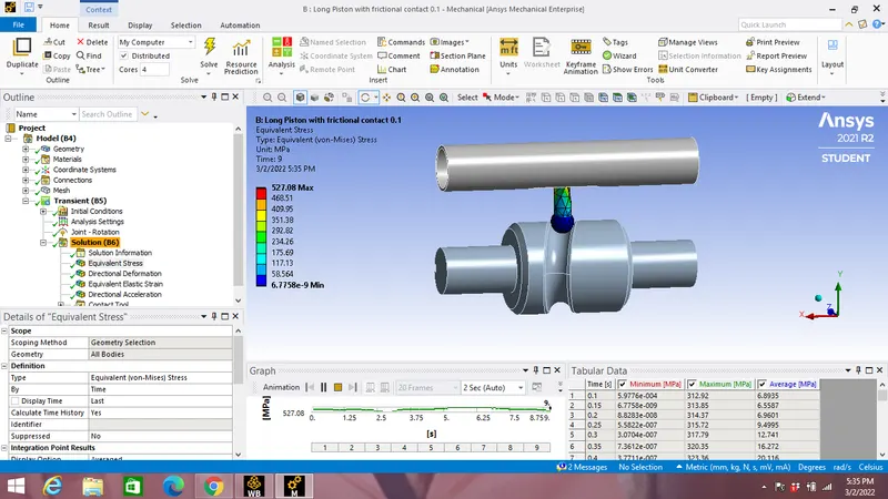
Stress vs Time graph:
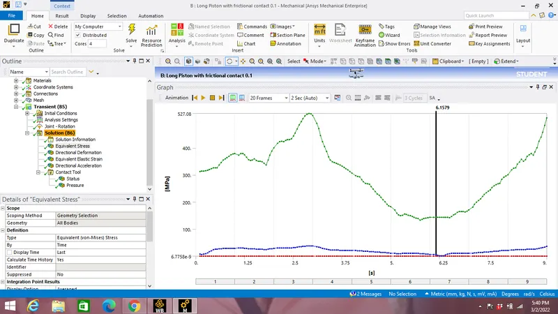
Maximum Equivalent Stress:527.08 MPa
Directional Deformation:
Directional deformation is taken along Z axis for the Follower as shown in the image below:
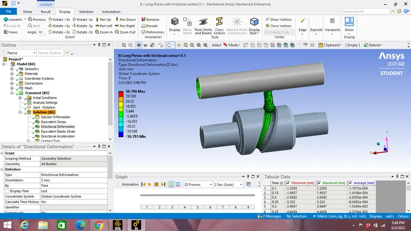
Maximum Directional deformation along Z axis:50.796 mm.
Equivalent Elastic Strain:
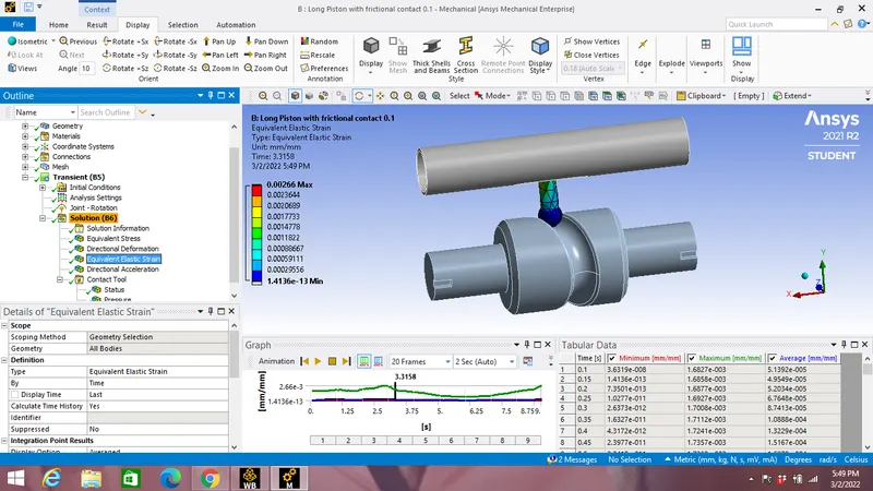
Equivalent Strain vs Time graph:
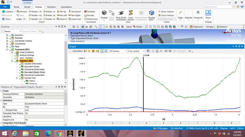
Maximum Equivalent Strain:2.66e-3
Case 3:
Frictional contact with 0.2 frictional coefficients:
Equivalent Stress of Cam's Follower:
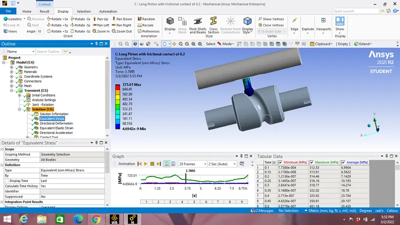
Stress vs Time graph:
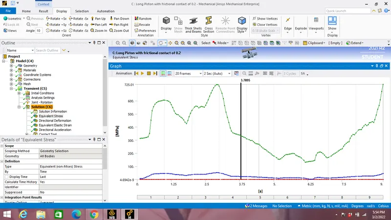
Maximum Equivalent Stress:725.01 MPa
Directional Deformation:
Directional deformation is taken along Z axis for the Follower as shown in the image below:
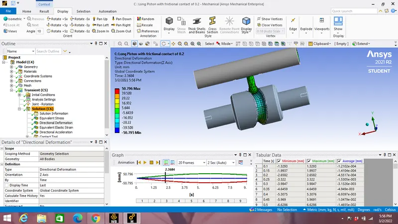
Maximum Directional deformation along Z axis:50.796 mm.
Equivalent Elastic Strain:
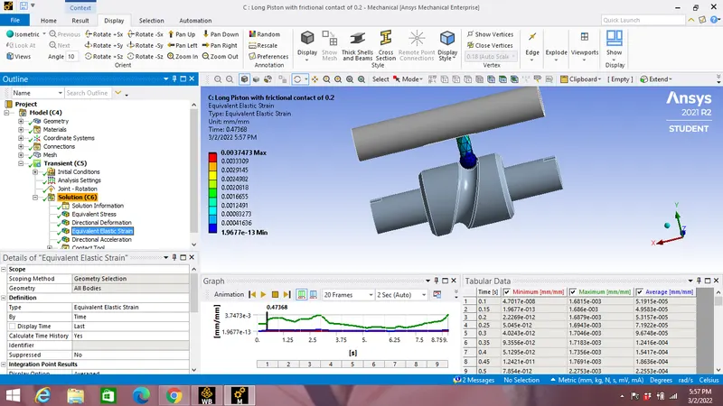
Equivalent Strain vs Time graph:
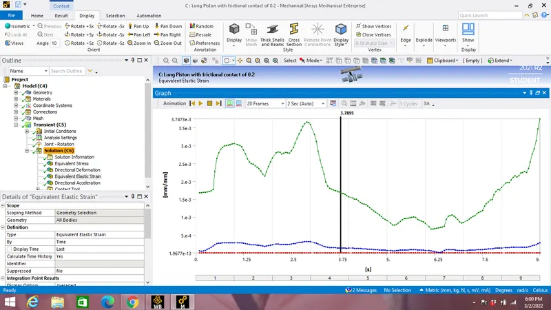
Maximum Equivalent Strain:3.7473e-3.
Comparision of Maximum Equivalent Stress,Strain and Directional deformation of case 1,2 and 3:
| Case | Maximum Equivalent Stress(MPa) | Directional Deformation along Z (mm) | Maximum Equivalent Strain |
| 1 | 410.17 | 50.796 | 2.0668e-3 |
| 2 | 527.08 | 50.796 | 2.66e-3 |
| 3 | 725.01 | 50.796 | 3.7473e-3 |
Conclusion:
- It can be seen from the table above that highest Maximum Equivalent Stress occurs for frictional contact with frictional coefficient of 0.1 as 725.01 MPa. So with increase in friction at the contact surface more work has to be doen against friction so high stress occurs at the contact areas.
- Directional Deformation along Z axis remains same for all the three cases.
- Highest maximum equivalent strain of 3.7473e-3 occurs for case 3 as the stress devloped was high in that particular case.