Assignment 6-Frontal Crash Simulation Challenge
Frontal crash challenge:
Aim:
- To perform frontal crash on vehicle against rigid wall in Hypermesh.
- To simulate the crash behaviour in Hyperview & simulate the results.
- To plot the sectional & axial forces at different location.
- To obtain intruion result on Dash wall and plot them in Hypergraph.
- To obtain acceleration on B-Pillar.
Case Setup & execution:
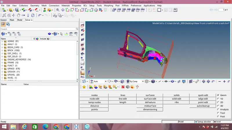
Import the .rad files in solver deck and frontal crash model obtained is shown in the image below:
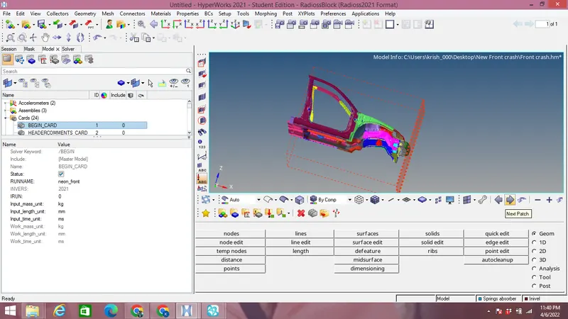
Check the unit system in the Model browser under Begin card as shown in the image below which contains Kg mm ms:
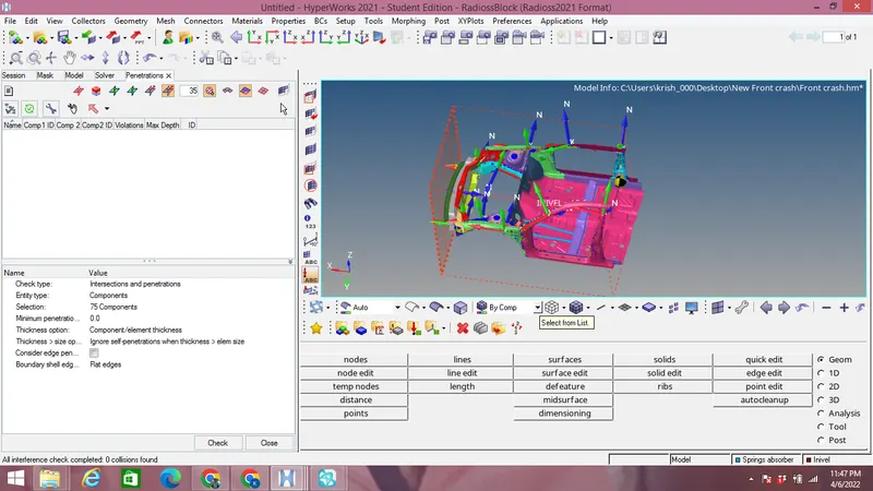
Check the penetration by going to Tools on menu bar & selecting the Penetration and select all the car model components for the penetration check as shown in the image below:
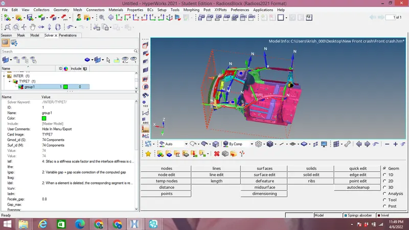
Create a Type 7 interface at Solver browser and delete the default interfaces with all the components as slave & master with perferable interface parameters as Istef=4,Idel=2,Fscale_gap=0.8 Stmin=1kN,Frict=0.2,Gap min=0.5,Iform=2 & Inacti=0 shown in the image below:
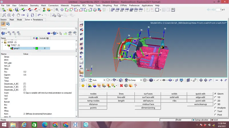
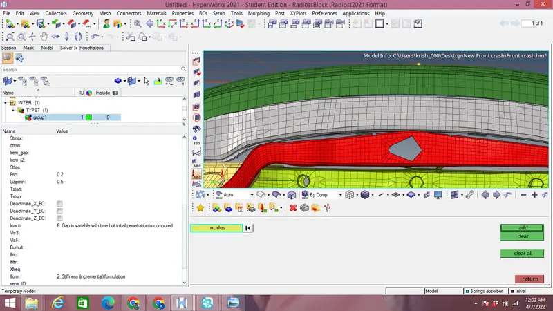
Create a rigid wall at the front side by selecting node at the outermost part of Bumper by creating a nodes using Temp nodes as shown in the image below:
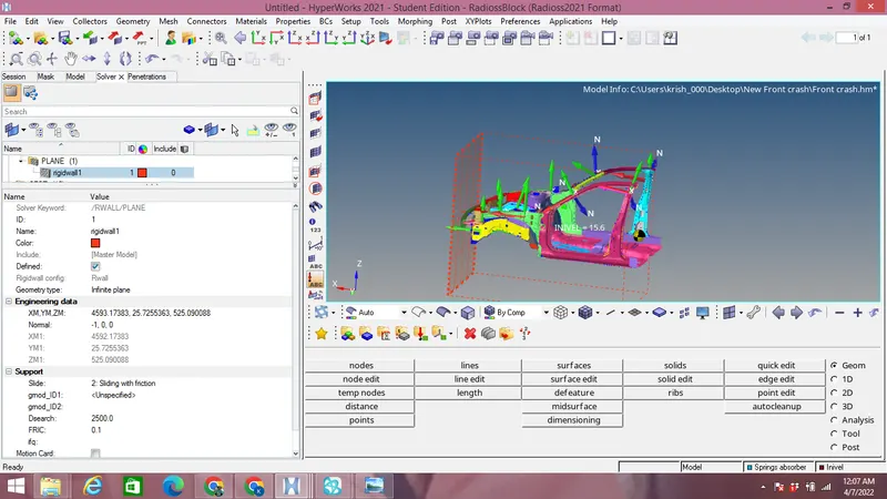
Go to solver browser & create a Plane Rigid wall by selecting the Nodes created above with D search as 2500 and Frict as 0.1 as shown in the image below:
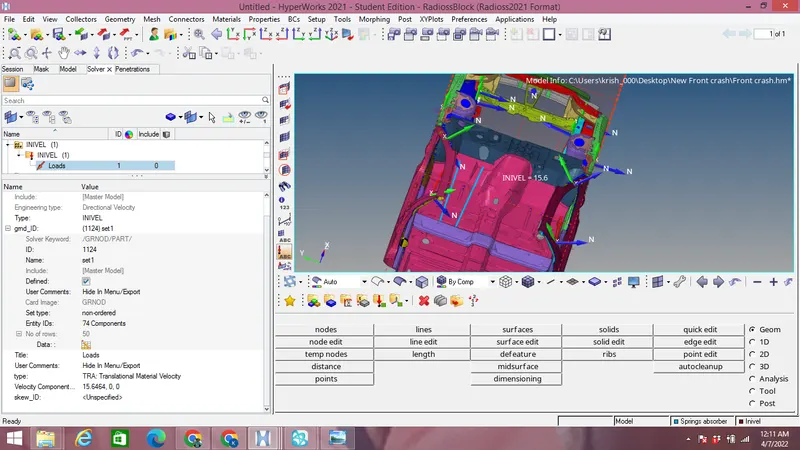
Create a intial velocity of 15.6464 mm/ms along X axis for the car component by right click-create-boundary canditions-Invel as shown in the image below by taking all the car components as shown in the image below:
Create the frame for sectional forces on A-pillar by right click-create-Frame-Mov on the solver browser by properly selecting origin,plane as yz with 3 nodes as shown in the image below:
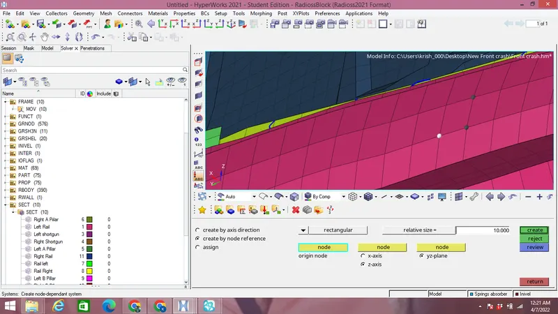
10 Frames are created out of which 4 are for Rails at node 174247 at both right & left,2 for Right & left Shortguns, Right & left A-Pillars, Right & left Right & left B-Pillars as shown in the image below:
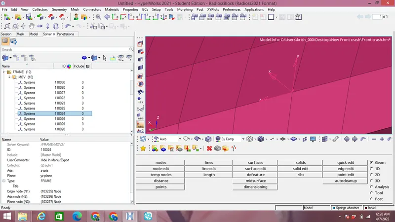
Create sections at Rail at node 174247,Left rails,Shortguns,A-pillars & B-Pillars by right click on Solver browser so that we can capture section force on A-Pillar,Axial force on rails due to Bumper,Shortguns as shown in the image below:
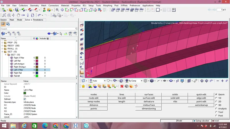
Assign the respective moving frame to the section by Frame ID created on that particular components & Nodes as shown in the image above,in gshell select the elements as shown in the image below:
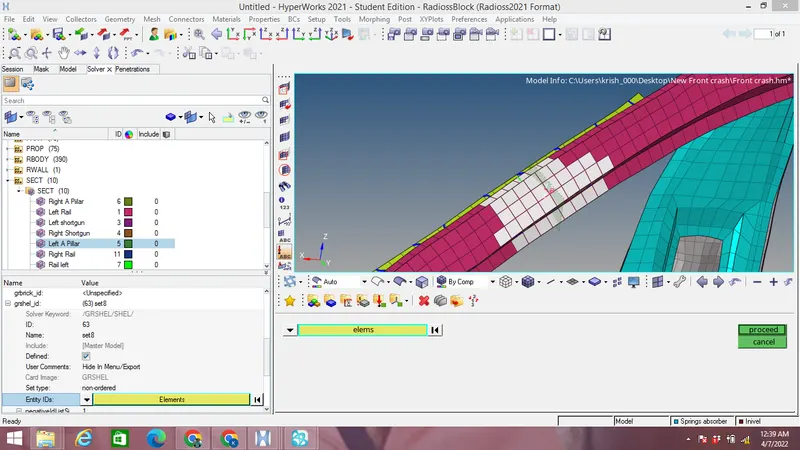
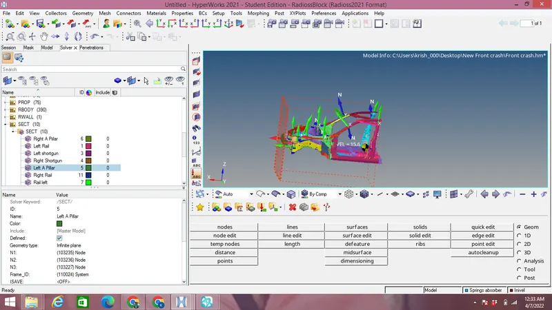
Finally created the 10 sections as shown in the image below:
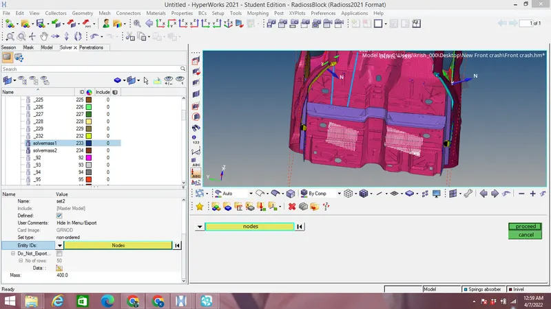
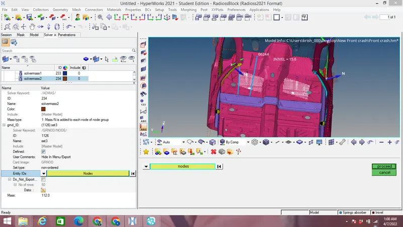
Add the mass of of 400 & 112 kg by selecting mass/node option by right click on selecting ADMAS option as shown in the image below:
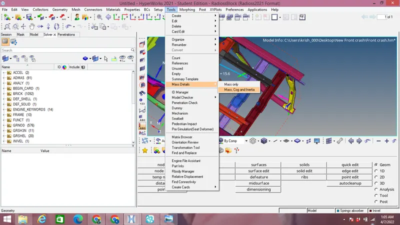
Now for checking the total mass & COG we go to Tools-mass details-mass,COG & Inertia as shown in the image below:
Now Total mass =700 kg with COG is checked as shown in the image below:
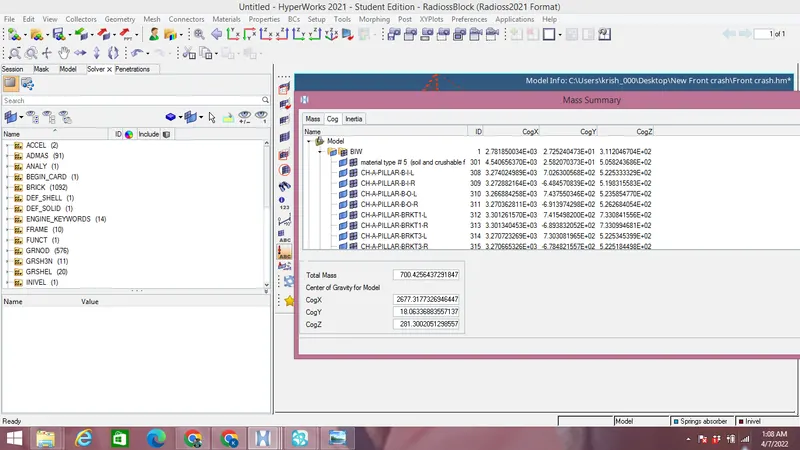
Final COG postion is shown in the image below:
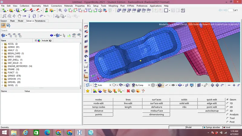
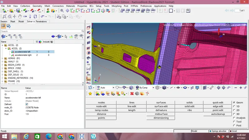
Create an accelerometer on B-Pillar rocker at both right & left by right click-Accel-selecting proper nodes with F-cut as 1.9 as shown in the image below:
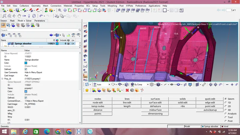
Create a spring to measure intrusion at nodes 66695 & 66244 by nodes translation with proper P4-SPRING property card with stiffness(K)=0.001 and Mass=0.0001 Kg as shown in the image below with springs creations at given 2 nodes:
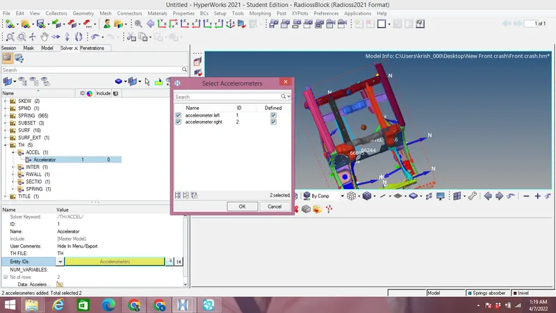
Create a Time history file at solver browser by right click-TH & name it as accelerometer select both the accelerometer as shown in the image below:
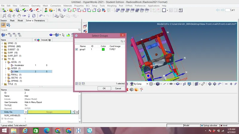
Like above create a Time history file for interface & select the interface as shown in the image below:
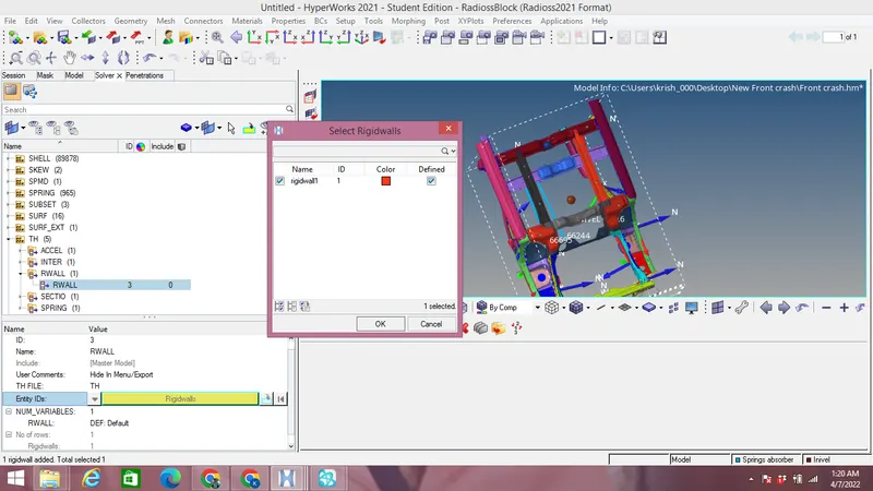
Like above create a Time history file for Rigid wall & select the rigid wall as shown in the image below:
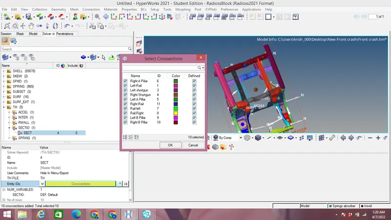
Like above create a Time history file for Sections & select the all the sections as shown in the image below:
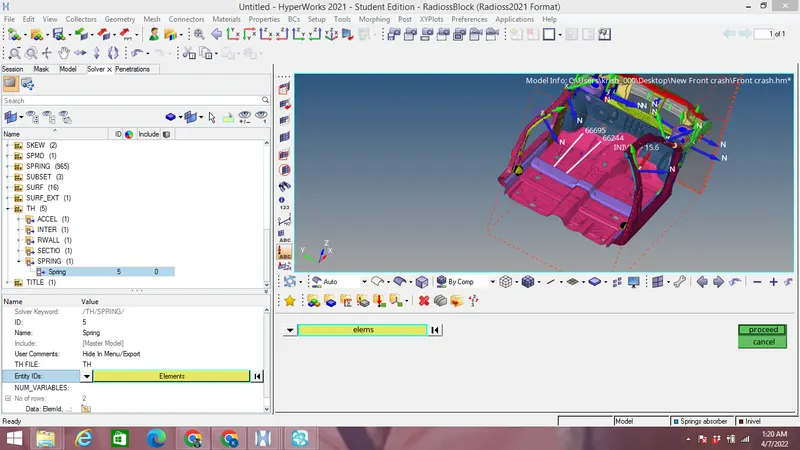
Like above create a Time history file for Springs & select the 1D elements as shown in the image below:
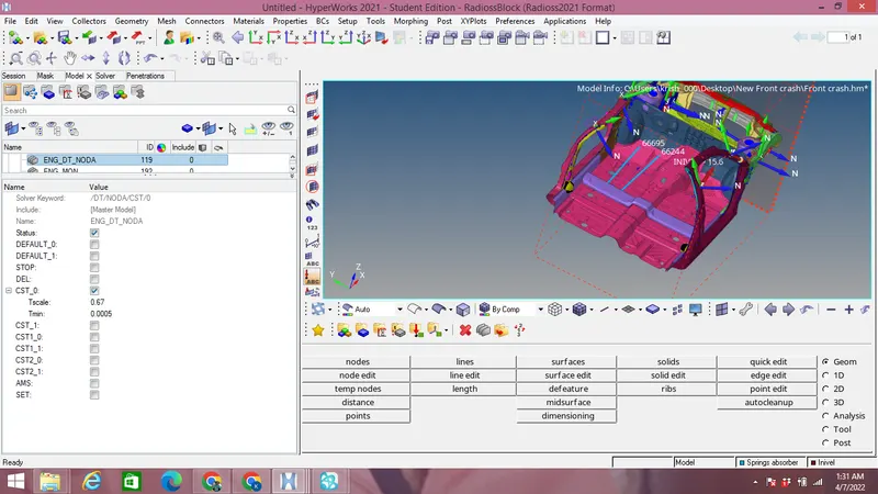
Check the animation time under model browser-Cards-Eng ANM-DT NODA as 0.5 to 0.1 ms as shown in the image below:
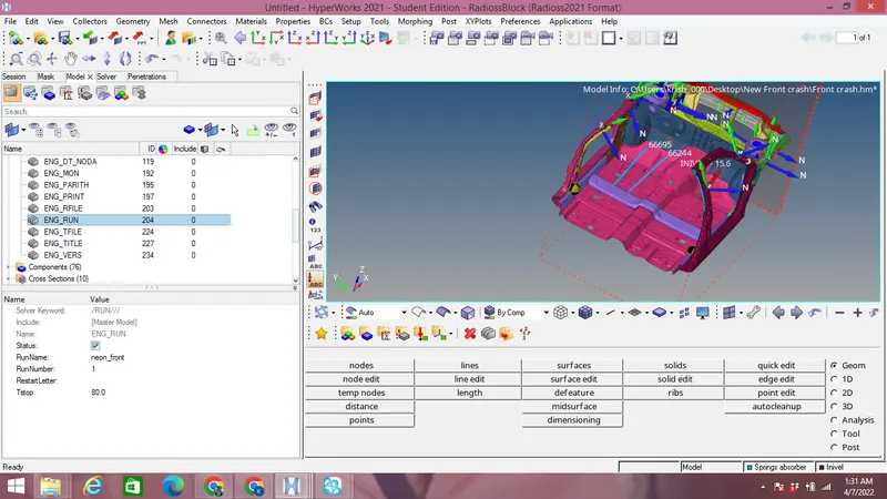
Check the Run time under model browser-Cards-Eng RUN as 80 ms as shown in the image below:
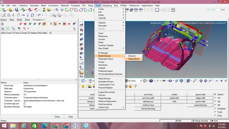
Go to Tools-Model checker option to check for any errors before running the simulation as shown in the image below:
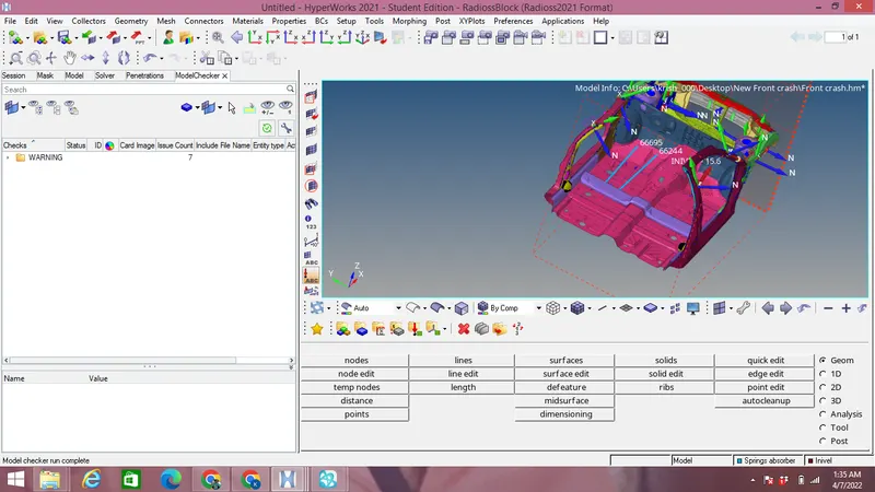
Next Run the model under Analysis-Radioss with -nt 4 threads of CPU and output files obtained are shown in the image below:
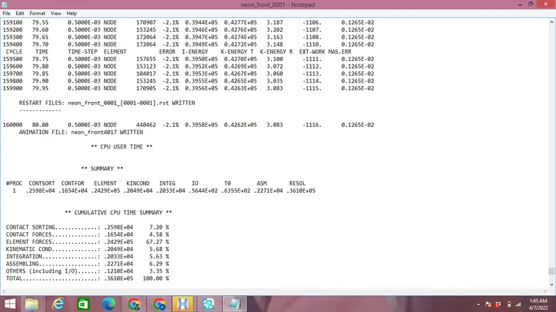
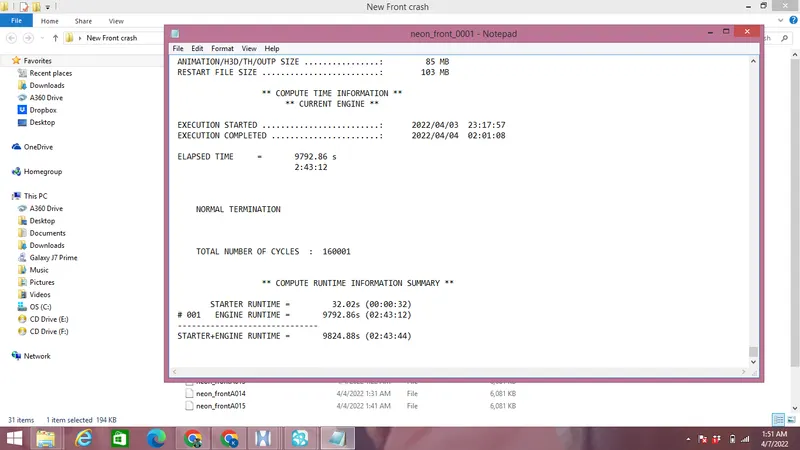
Maximum Energy error is -2.1 % and mass error is 0.126E-02 as shown in the image above with 160001 cycles & Starter+Engine Run time as 9824.88s.
Observation:
To view the simulation go to Hyperview mode from hypermesh & select the .h3d files as shown in the image below :
Plot of displacement vs time simulation is shown in the image below:
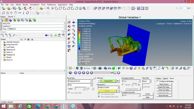
Maximum displacement of 1.227E+03 mm as shown in the image above.
Von misses stress vs time plot is shown in the image below:
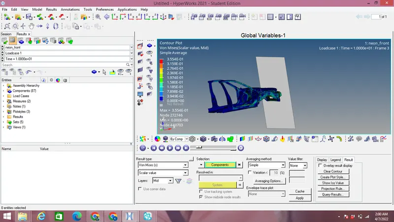
Maximum Von Mises stress obtained is 0.3544 Mpa as observed from the simulation above. Overall stress distribution is quite good in vehicle as seen from the plot above.
Now for plotting graphs we switch from Hyperview to Hypergraphs 2D and select the .T01 files as shown in the image below:
Energies plot:
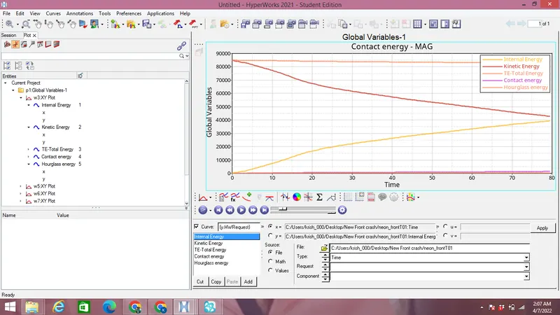
From the plot above we can see that there is high amount of Kinetic energy at the start of simulation but as the simulation progress the kinetic energy in the vehicle decreases and it gets converted into internal energy but Total energy of the system is almost constant to 85000 J as shown in the image above.Some contact energy is created due to type 7 interface with 0.1 friction.
Cross sectional forces plot:
A-Pillar:
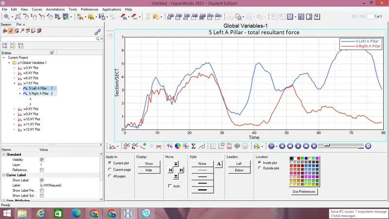
Forces on left A-Pillar is more than right A Pillar as seen from image above.
Shortgun:
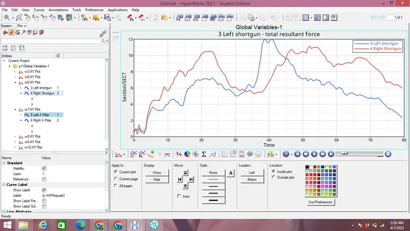
Resultant force on the left shortgun is higher than right as seen from the image above.
Axial force due to Bumper on rails:
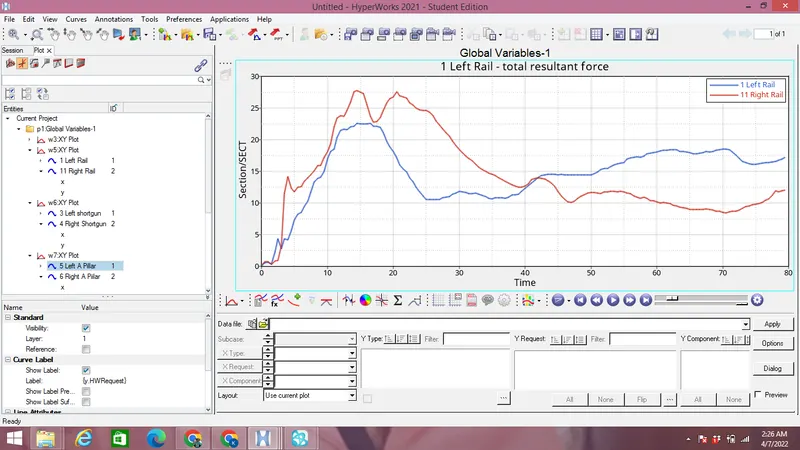
It can be seen that effect of forces by bumper occurs higher in right rail than left one as seen from the images above.
Accelerometer:
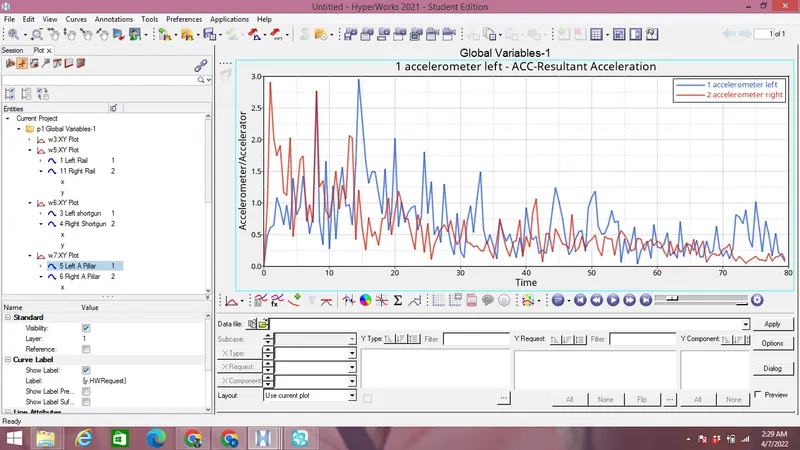
Intially acceleration on right B-Pillar was higher but as the simulation progress acceleration of left B-pillar is more or similar to right B-pillar as shown in the image above.
Intrusions:
Spring connecting nodes 66695 & 66244 with Spring element ID's are shown in the image below:
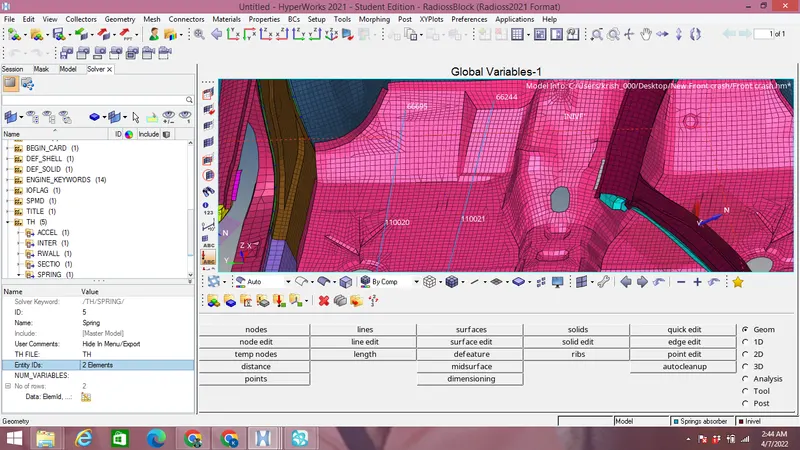
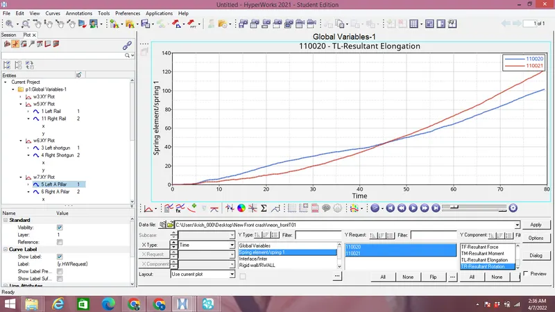
Total resultant Elongation on springs connected at both the nodes with respective spring element ID's from above shows that node 66244 is displaced 120 mm while node 66695 as 100 mm.
Conclusion:
The vehicle model impact on the rigid wall to study for the frontal crash secanrio alongwith accelerations,displacement & forces devloped at various points.