Assignment 2-RADIOSS Engine File Editing & 3D Meshing Challenge
Radioss Engine file editing & 3D mesh challenge:
Aim:
- To check the material properties of rail component & calculate speed of sound in steel rail.
- To calculate time taken by shock wave to travel from one end of the rail to the other end of rail of length 1000mm.
- To edit the engine file so that stress wave can be monitored moving from one end of the rail to the other end during impact.
- To set the frequency animation output to the time that will give 20 animation steps in the engine file.
- To perform 3D mesh on the given component with quality parameters & size mentioned above.
Steps followed:
Importing the Radioss starter file :
- Calculate the speed of sound(c) in steel rail=√(E/ρ), were E=Young's modulus,ρ=Density of steel rail as shown in the image below of 0000.rad file.
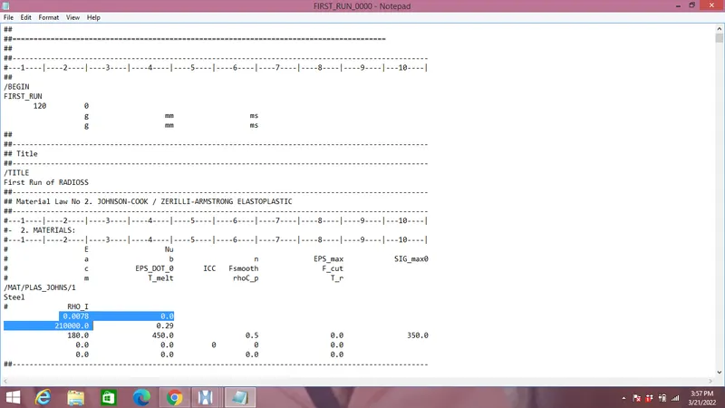
E=21000MPa, ρ=0.0078 g/mm^3.
c=√(21000/0.0078)=5188.75mm/ms.
- Time(t) taken for the shock wave to travel from the one end of the rail to other end of 1000mm length(l).
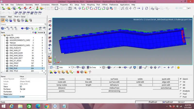
t=l/c=1000/5188.75=0.1927 ms.
- Time for sound to travel length of rail=0.1927 ms.
- Engine file edited according to the above calculated value as shown in the image below:
- Set the frequency of animation output to a time that will give 20 animation time steps.
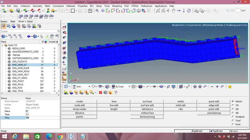
Frequency=(1/t)*time step=(1/0.1927)*20=104 Hz.
Set the above calculated frequency in 0001.rad file as shown in the image below:
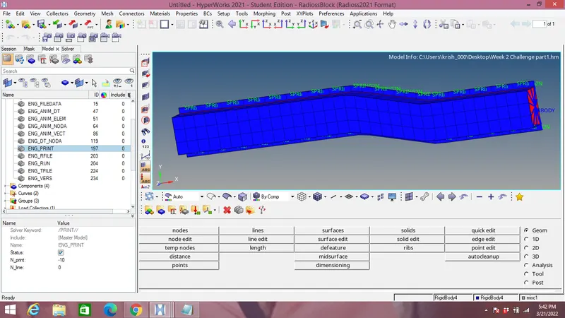
- Set the N_print value as -10.
- Now after changing all the values export the solver deck files in solver .rad format.
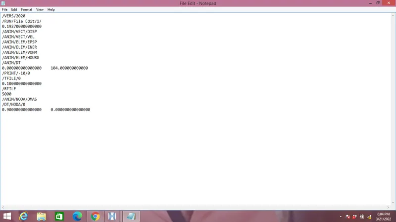
- The image above is the final radioss engine file after making all the changes.
- The edited radioss file is attached below.
1D Meshing:
Aim:
To mesh the file imported & connect it by 1D truss connector.
Steps followed:
- Import the model & open the file in .hm format in Hypermesh software.
- Mesh both the surface as shown in the image below.
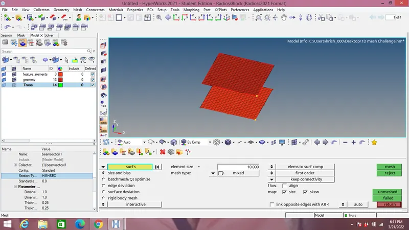
- Create a copmonent & make it current qand go to 1D panel and select the rods option and select the each node at different body to connect with 1D element of truss as shown in the image below.
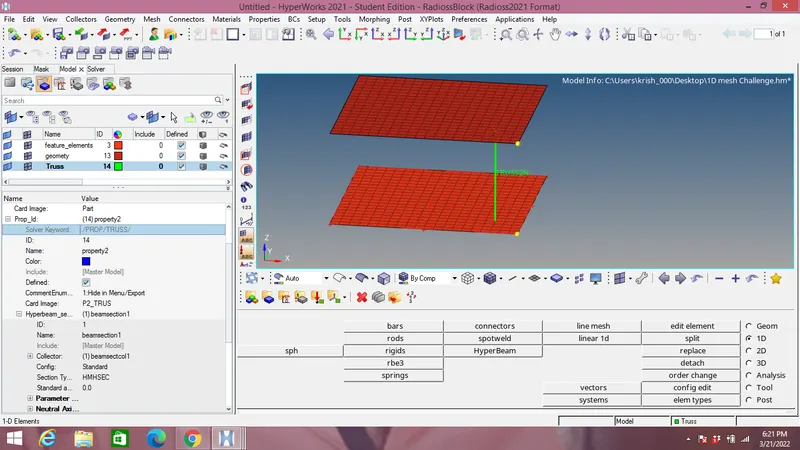
- After creating the truss 1D element go to Property Id and select card image as of "P2 Trus" type.
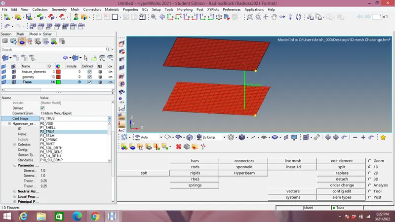
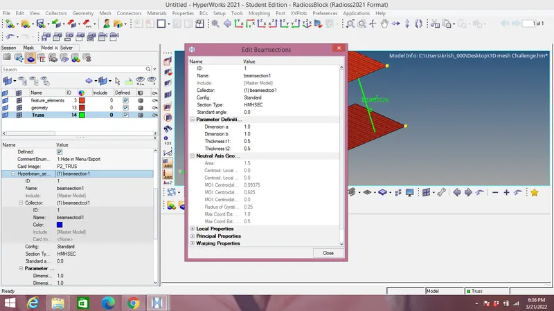
- Create new hyperbeam section & select the required cross section which is I section here as shown in the image below:
3D tetra & hexamesh model:
Steps followed:
- Import the model & open it directlt in hypermesh since it is .hm format as shown in the image below.
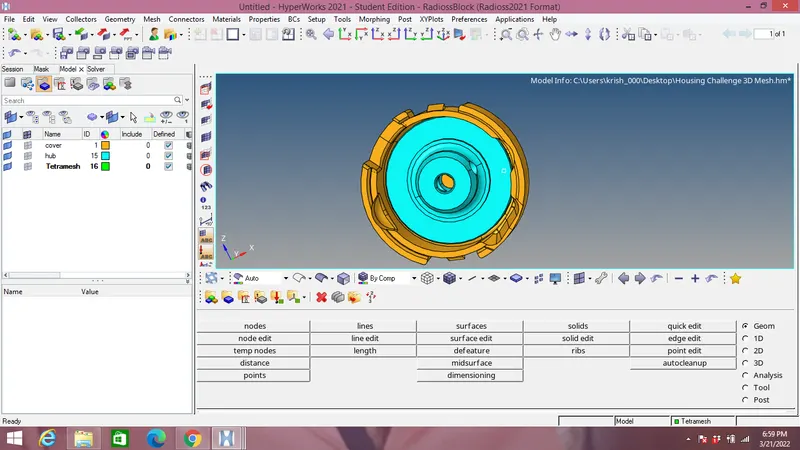
- After checking for geometrical errors in this case if not found any, start 2D meshing of hub with element size as 5mm with tria elements as shown in the image below:
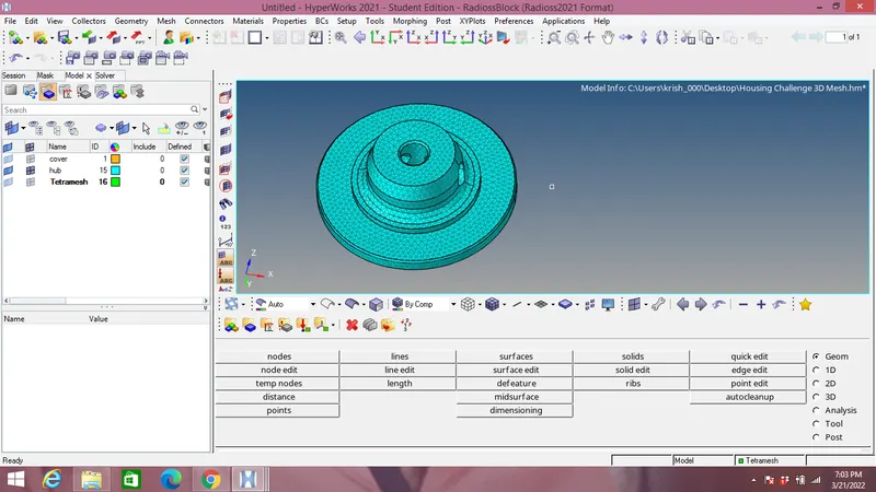
- After this we do 3D tetra meshing with required tet collapse value of 0.15 & target element size as 5mm in 3D panel as shown in the image below:
- Delete 2D tria mesh & check whether its deleted or not with the help of mask command in tool panel as shown in the image below:
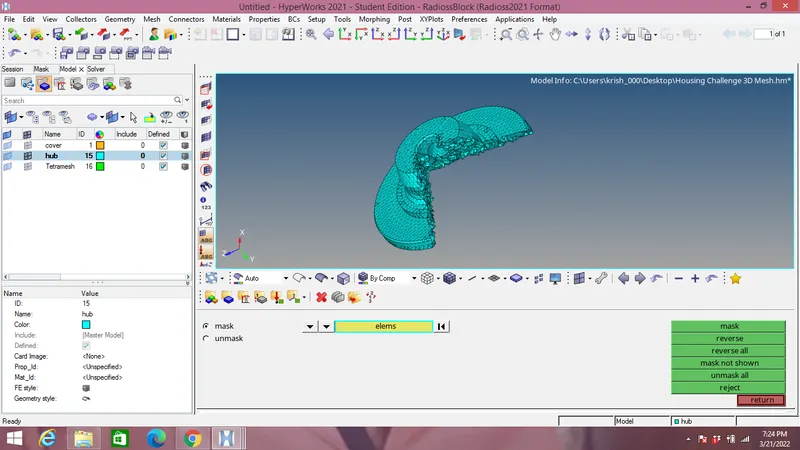
- Do the same with Cover by creating a tertamesh component for cover & check for 3D elements by mask option in tool panel.
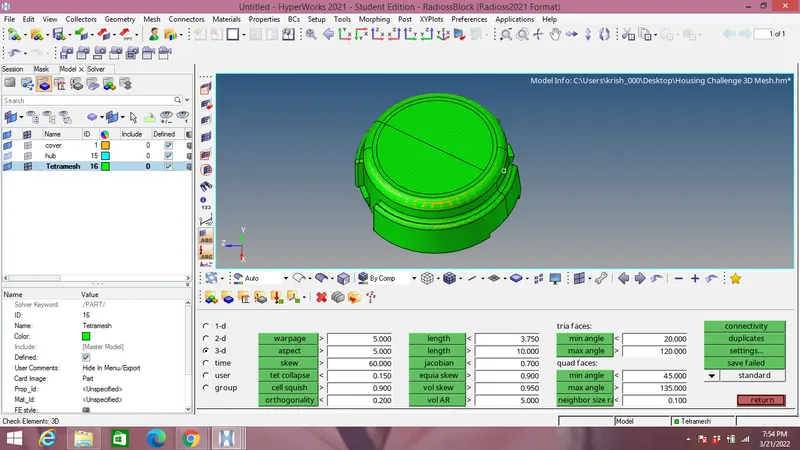
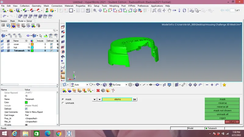
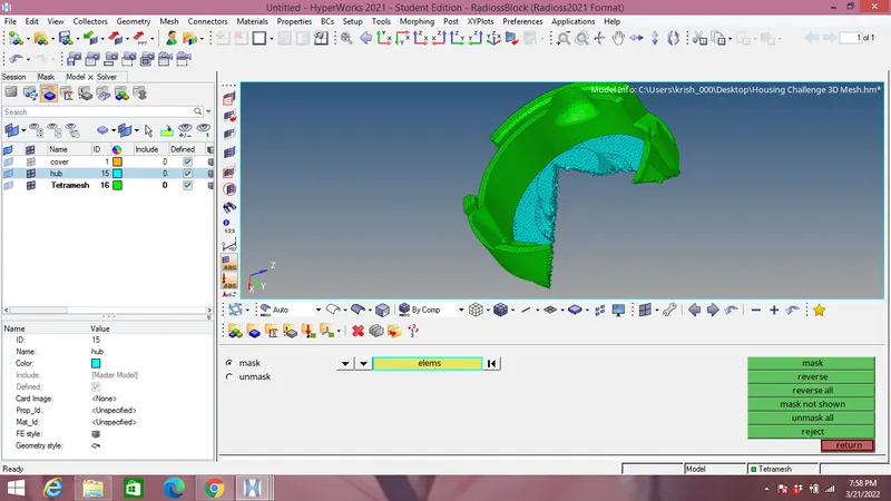
Mask the entire assembly of Hub & Cover to check that 3D tetramesh element exists. as shown in the image below:
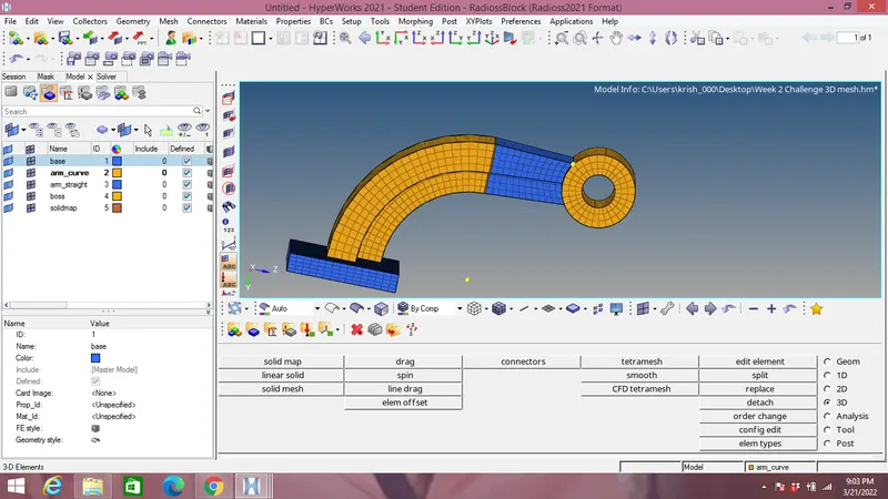
3D Hexamesh of Arm-Bracket model:
Steps followed:
- In this model we have four components which are meshed one by one.
- We have several steps for hexamesh in 3D panel like linear solid,element offset,spin, solid maps, stc.
- We have used several steps depending upon geometry of each component.
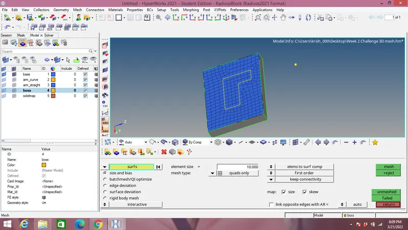
- The base is meshed with quad element in 2D panel by selecting its one face with element size of 10 mm as shown in the image below:
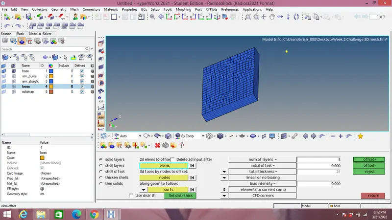
- With element offset option in 3D panel we mesh other faces of base as shown in the image below:
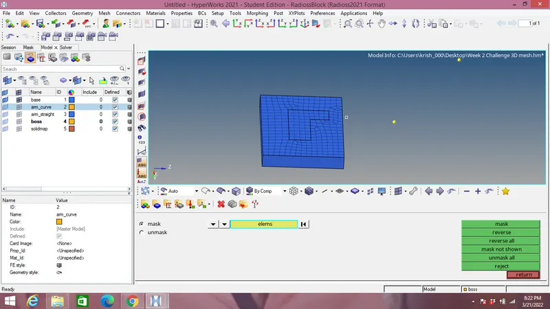
- Next the arm curve is meshed into 3D element by masking the hex8 element in base component as shown in the image below:
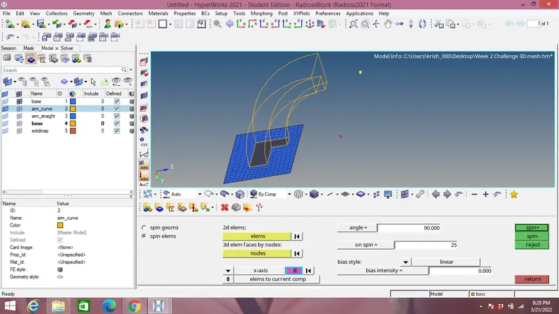
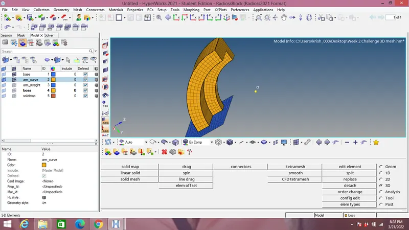
- Now the spin option is chosen in 3D panel for meshing arm curve by making centre of circle curve and selecting elements as shown in the image below:
- To mesh the arm straight component use linear option under 3D panel.
- We are meshing the free end face of straight arm by 2D elements after selecting face of curve arm and creating a face component as shown in the image below:
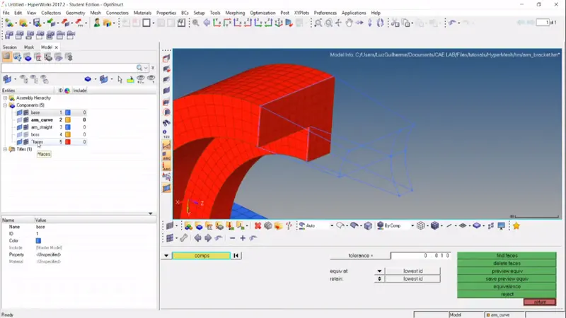
One end of straight arm meshed with same number of 2D elements as staright arm face:
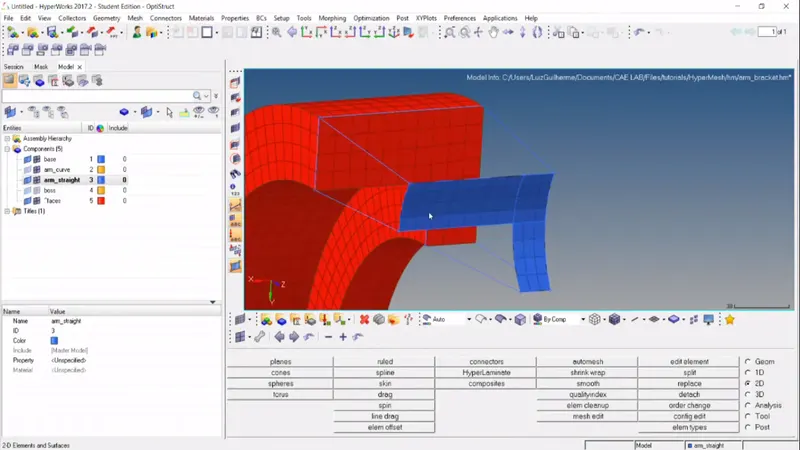
- Using linear solid option in 3D panel with source & destination elements with equivalent node on equivalent element 3D meshing is doen on the straight arm as shown below:
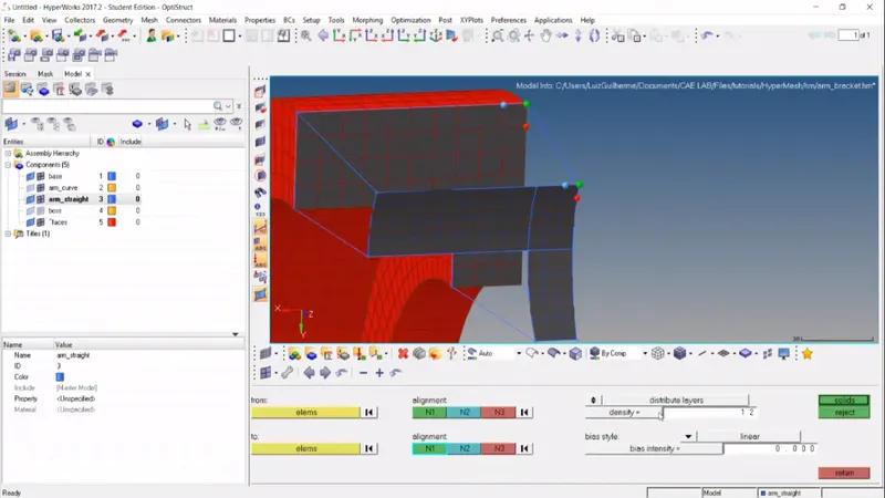
Finally meshing of straight arm is doen:
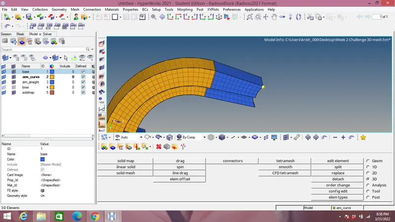
- To mesh the boss component we use solid map option in 3D panel.
- Mesh the boss to one side by 2D elements & solid map the elements to the other end of boss using nodes.
- After meshing all the components the 2D elements by delete option-by configuration-quad4 as shown in the image below:
Conclusion:
- Speed of sound,shock waves,time & frequency are calculated depending on steel rail material with 20 time steps
- Radioss file which is .rad format is edited.
- 1 D mesh elements are applied.
- 3D Tetra & Hexamesh elements with 5mm & 10mm size respectively with tet collapse of 0.15 is applied.