Assignment 7-Side Pole Crash Simulation Challenge
Aim: Side crash challenge.
Objective:
- To check the unit system and ethier follow Kg,mm,ms unit.
- To create an appropriate interface of friction 0.2 with recommended parameters.
- Check penetrations & intersections.
- Correct rigid body if any isssues.
- Create a rigid wall with friction 0.1 as per the reference model.
- Compare the model weight with the reference model and use added masses to reach the target weight of 700kg while getting CG about the required range.
- Initial velocity - 20mph, as per the standards.
- Use model checker to ensure good quality.
- Timestep :0.5 to 0.1 microseconds.
- Run 80ms.
Steps to be followed:
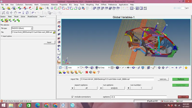
Import the 0000.rad starter file as shown in the image below:
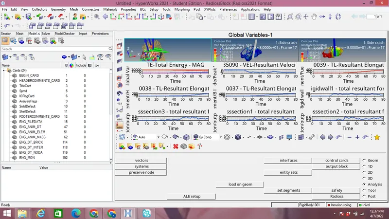
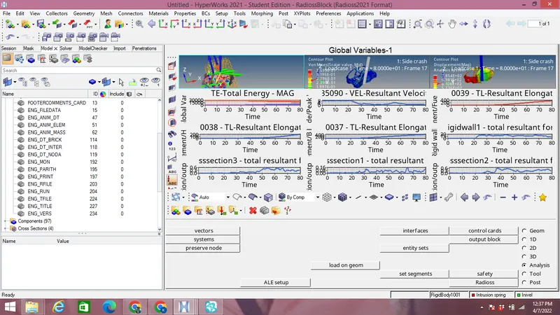
Create the Cards required for simulation such as Time_step Control,ENG CARD,ENG DT NODA,ENG DT BRICK,ENG ANIM ELEM ENG RUN,ENG PARITH etc under model browser as shown in the image below:
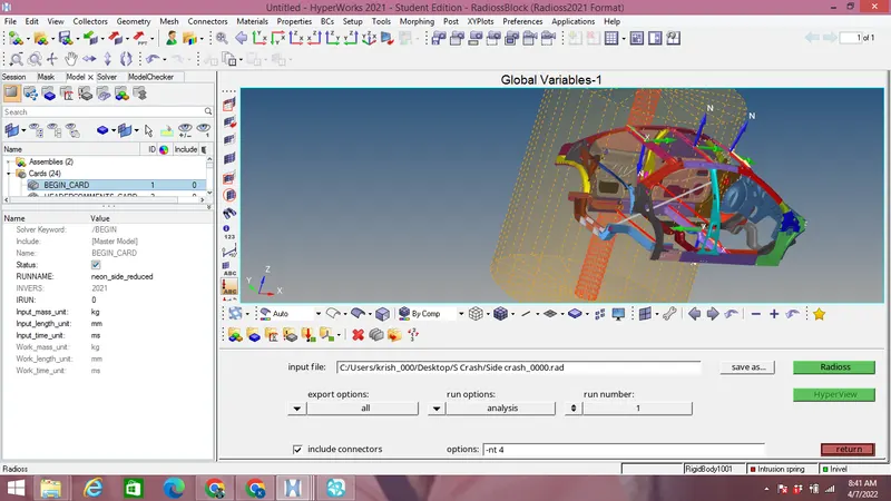
Check for unit system in Model-Begin cards as shown in the image below:
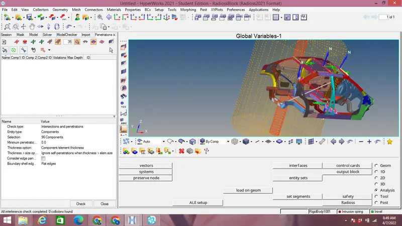
Check for penetration & intersection with penetration check under Tool menu in menu bar as shown in the image:
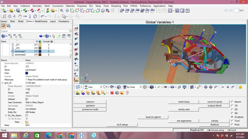
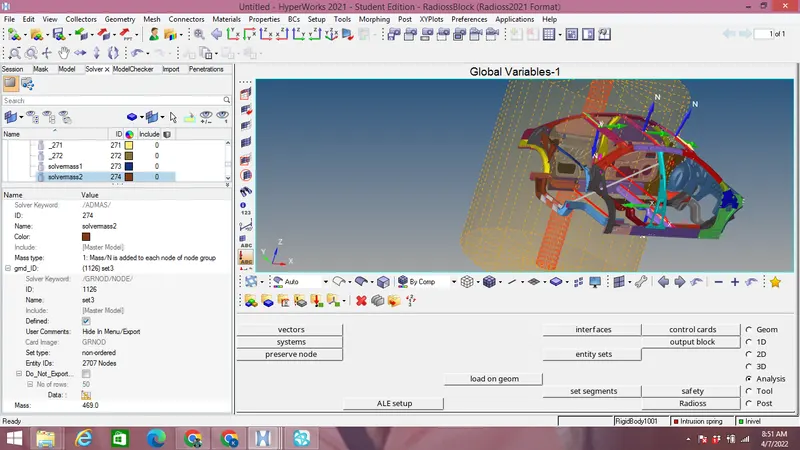
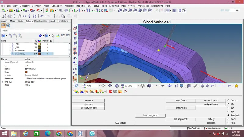
Add masses of total 700 Kg with proper mass balancing by Tool-mass,cog & inertia option.Compare the model weight with the reference model and use added masses to reach the target weight of 700kg while getting CG about the required range by using ADMAS option by right click on solver browser with proper nodes and mass of 65Kg & 469 kg is added to solver mass shown in the image below:
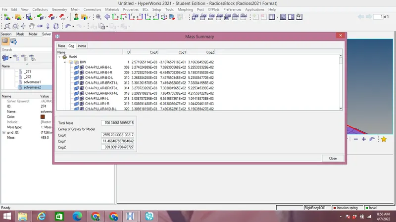
Cog is found out as shown in the image below:
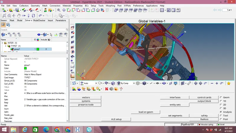
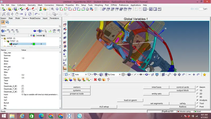
Create an appropriate Type 7 interface with friction as 0.2 and recommended parameters by right click on solver browser with INTER option as shown in the image below:
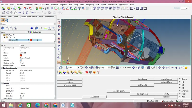
Create a rigid cylindrical wall with outermost node at side wall with 254 mm diameter & Dsearch as 1000 & friction 0.1 as per the reference model by right click on the solver-Rwall-Cyl as shown in the image below:
Initial velocity of 8.94mm/ms along Y axis as per the standards is applied to the car model by right click-Invel-Components-All as shown in the image below:
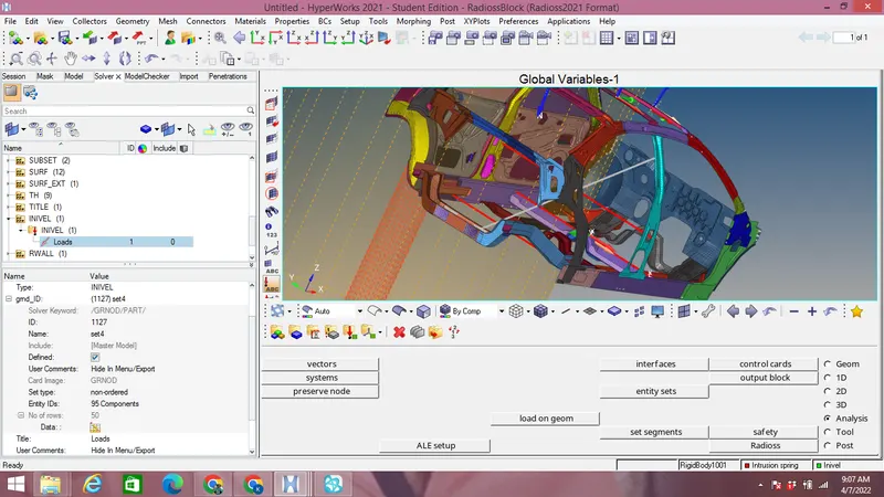
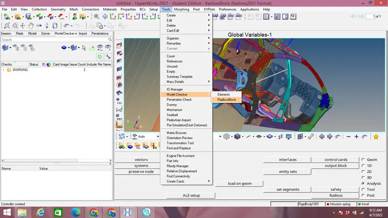
Use model checker to ensure good quality as shown in the image below by Tool-Model checker option as shown in the image below:
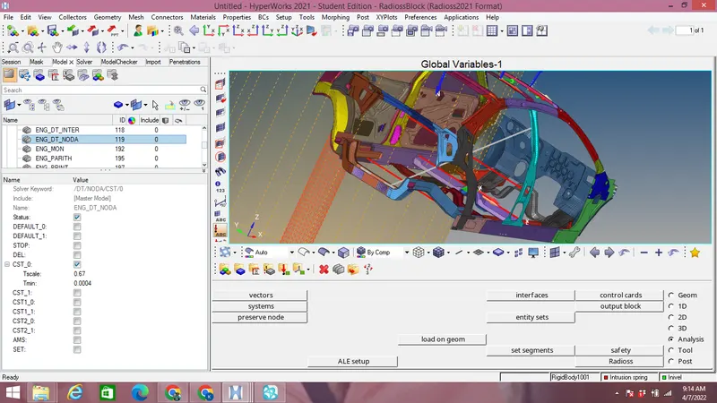
Timestep :0.5 to 0.1 microseconds under ENG ANIM DT NODA option under model browser-Cards as shown in the image below:
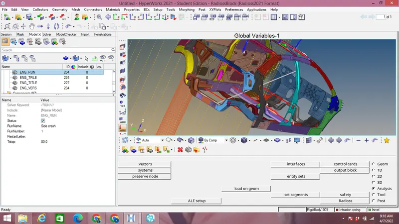
Run time of 80ms is edited under Cards-ENG RUN option in model browser as shown in the image below:
Create moving frames for the section by right click-frames-Mov as shown in the image below:
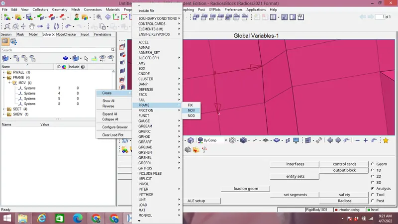
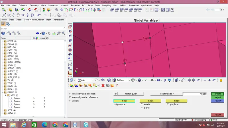
4 moving frames are created as shown in the image above.
Create 4 scetions on cross members on which forces are to be found by right click-sect-sect-Frame Id on Solver browser which is created above with proper Nodes selection as that of frame,Elements selected as shown in the image below.
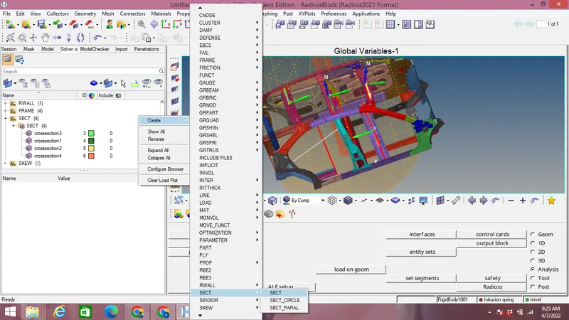
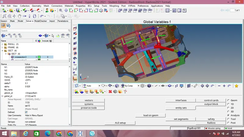
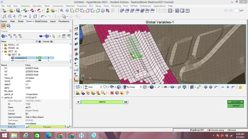
4 Cross sections similarly are created as shown above for measurements of forces in cross members.
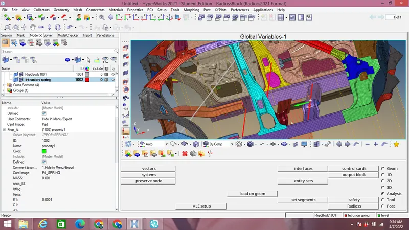
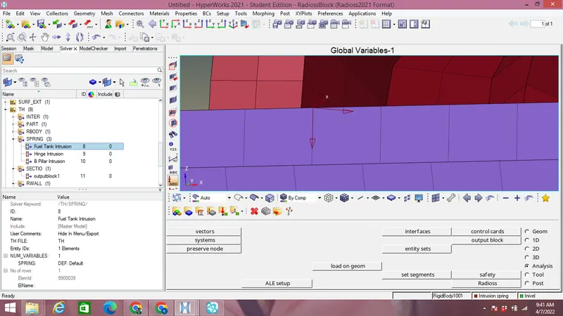
Create springs to find out Intrusion on Hinge Pillar,Fuel tank & B-Pillar with P4_SPRING property mass as 0.0001 kg,k=0.001 Kg as shown in the image below:
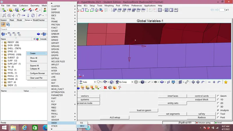
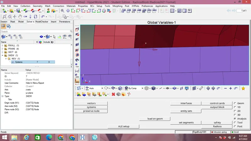
Create a Skew for peak velocity at the opposite to the inner node of door in solver browser-righ click-skew as shown in the image below as shown in the image below:
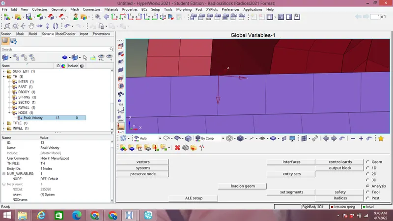
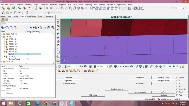
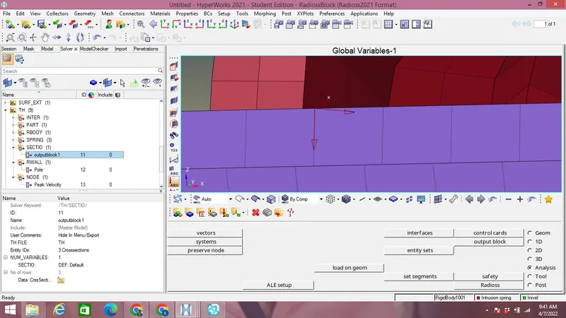
Create a Time history files & request for Peak velocity,Rigid wall forces,Interfaces,Intrusion by righ click-TH on solver browser as shown in the image below:
Peak velocity:
Rigid wall forces:
Section forces:
Intrusions:
Rigid body:
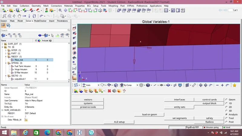
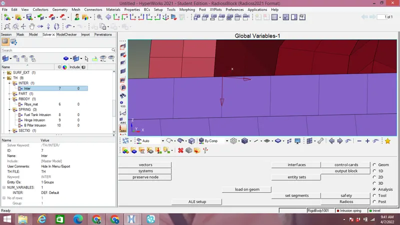
Interface:
Now Run the Analysis & Look at the energy & mass errors as shown in the image below:
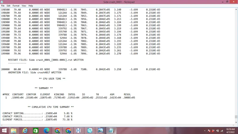
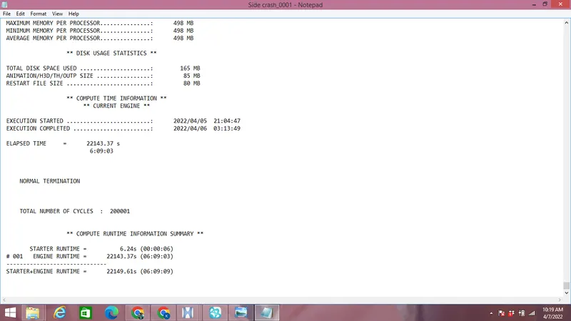
Energy Error is -1.6% with total number of cycles 200001 as shown in the image above.
Observation:
Von mises Stress plot:
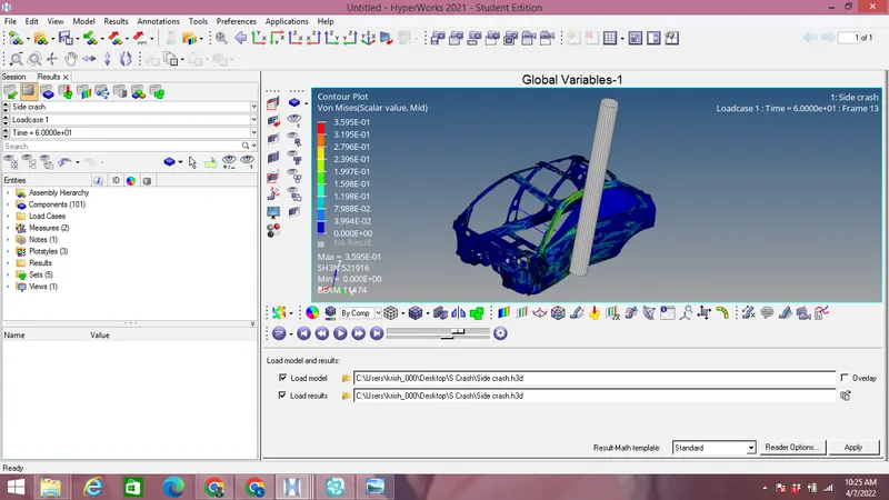
Maximum Von-mises stress observed is 0.3959 Mpa as shown in the image above while in vehicle stress distribution is better with less stress concentration.Generally stresses is more in B-Pillar is more since it takes the impact directly than its transferred to the other cross members.
Displacement vs Time plot:
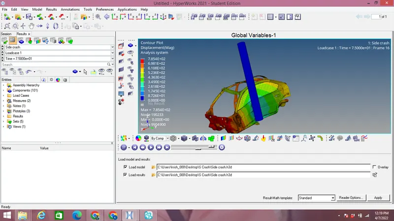
Maximum displacement observed from the image above is 785.4 mm.
Switch to Hypergraph 2D from the Hyperview mode to plot graphs:
Energies vs Time graph:
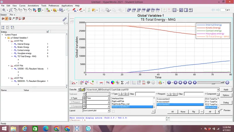
Decrease in Kinetic energy occurs due to decrease in intial velocity of the car after collision while Internal energy increases due to increase of potential energy stored in the car after collisions.Total energy of the system remains constant with slight decrease after loss as seen from the image above.While the contact energy & hourglass energies are almost negeligible as shown in the image above.
Peak velocity at inner node of door vs time graph:
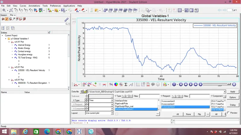
From the graph above we can see that Peak velocity at the inner node is between 9 & 10 and after collision it decreases as shown in the image above.
Rigid wall forces vs time plot:
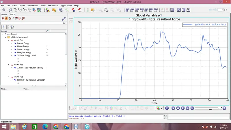
At the start of simulation rigid wall force is 0 after simulation it increases to 25 then again after collision it decreases as shown in the image above.
Sectional forces on the members:
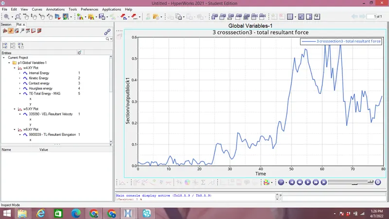
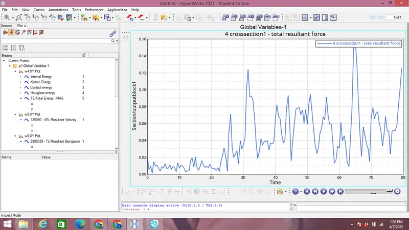
Maximum sectional force on B-Pillar cross section is 0.16 kN at 65 ms as seen in the image above.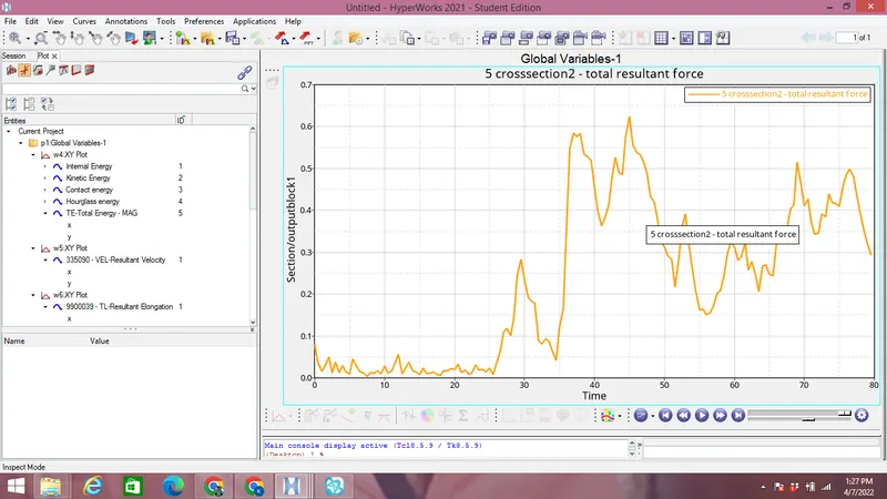
Maximum sectional force transferred to the left of driver seat cross section is 0.6 kN at 45ms as seen from the image above.
Cross memebers are very important in side crash analysis as they had prevent car body to deform inward after impact.Maximum Forces transferred to the left side of cross section is greater than 0.6 kN at 45 ms as seen in the image above while that at the B-Pillar memeber during crash is 0.16 kN at 65 ms.
Intrusions:
Intrusion on Fuel Tank:
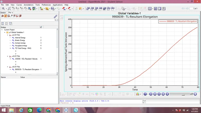
Maximum intrusion at fuel tank is 350 mm.
Intrusion at hinge pillar:
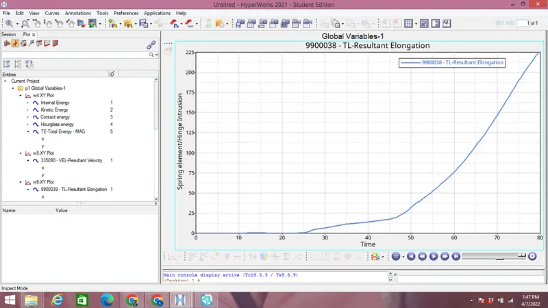
Maximum Intrusion at the Hinge Pillar is 225 mm as seen from the image above.
Intrusion at B-Pillar:
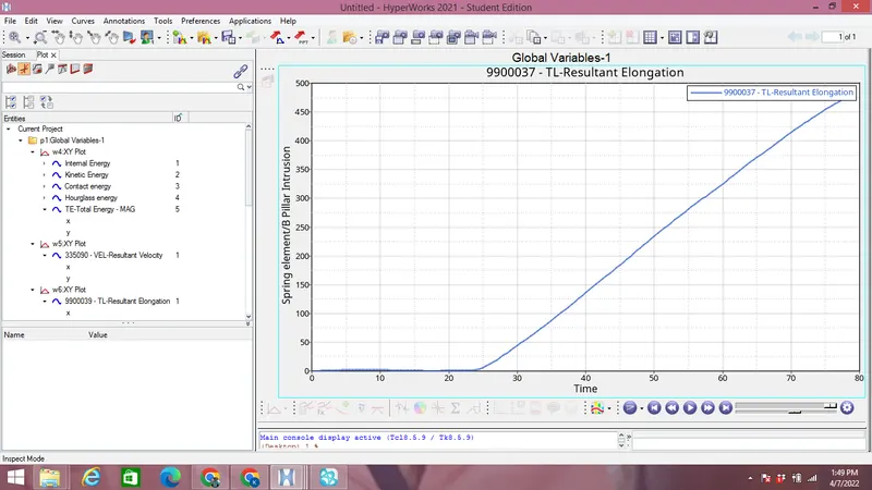
Maximum intrusion at B- Pillar is close to 500mm as seen from the image above.
Conclusion:
Side crash analysis is carried out in given BIW model of the Dodge Neon. The output requests is generated after creation of cross section with Peak velocity & intrusions were also measured.
Fuel tank intrusion can be in general reduced after using anti-intrusion beams between the pillars but we have to consider again weight to cost factor into our consideration for the vehicles.We can use composite materials other than steel for weight to cost values.