Week 8 Worm Gear Challenge
Transient structural analysis on a worm gear assembly.
Aim: Performing transient structural analysis on worm gear assembly by taking half part of gear with worm wheels.
Steps followed:
1)Material selection:
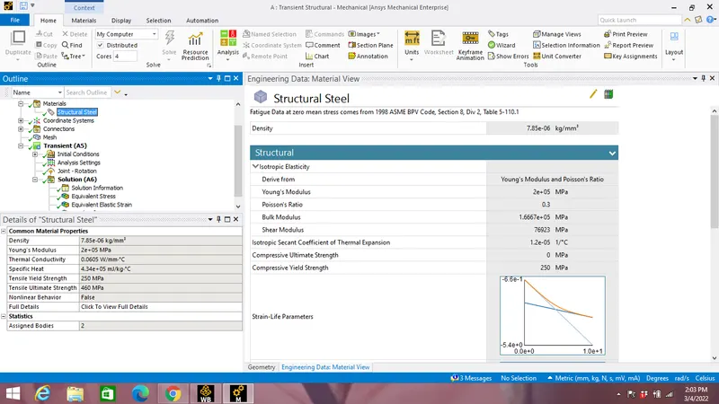
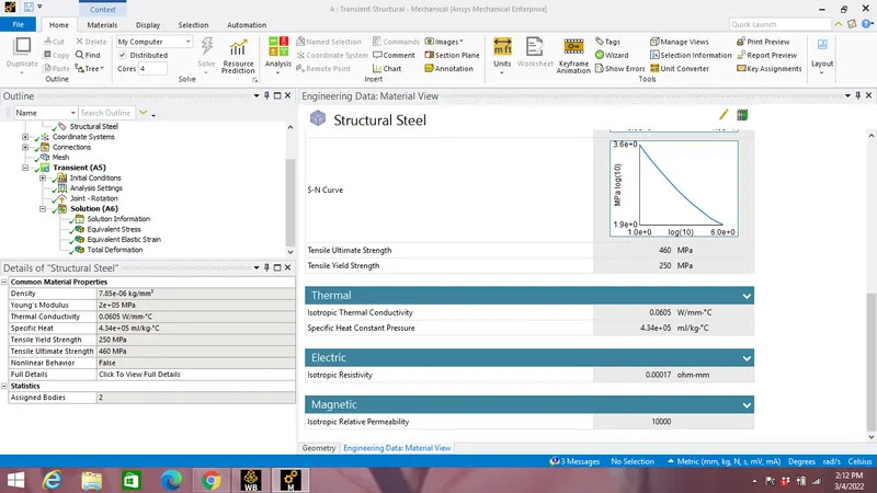
Structural Steel is choosen as material for all the components with material specifications as shown in the image below:
2)Geometry:
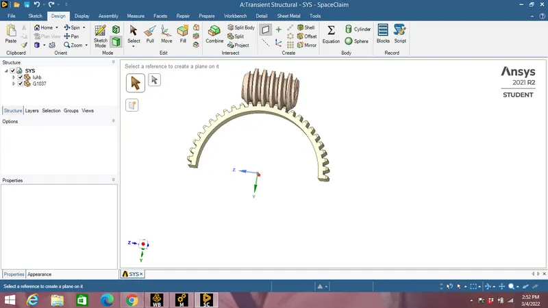
Gear of entire Worm-Gear assembly is cut in half by selecting a plane in half part of gear using Spilt body option in Geometry settings as shown in the image below:
3)Models:
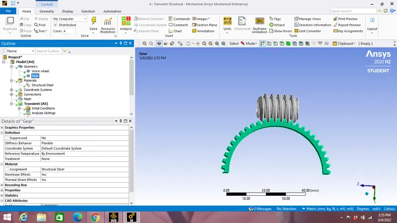
In models parts are renamed as worm wheel & gear with structural steel material assingnment to gear a shown in the image below:
4) Contacts:
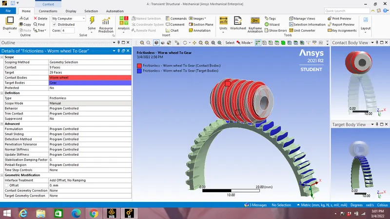
Frictionless contact is applied between worm wheel & gears by selecting worm wheel as contact & gear as target.
The faces of worm wheel & gears are selected as shown in the image below:
5)Joints:
Revolute joint:
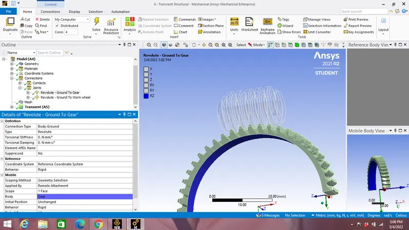
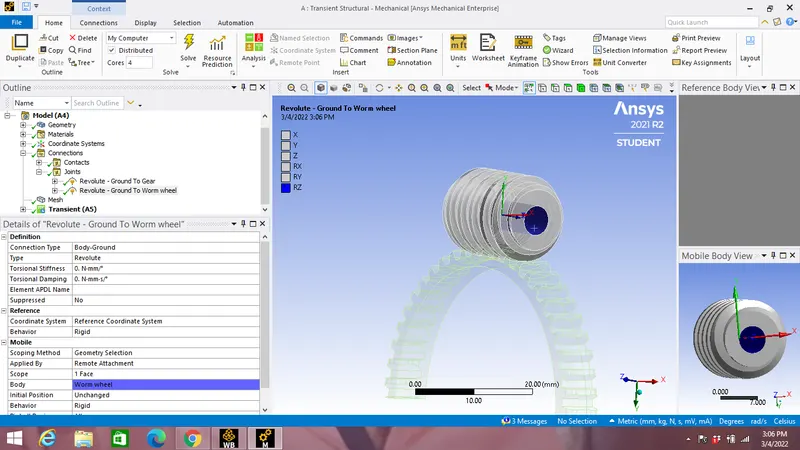
Two Body-Ground Connection type revolute joint is applied by selecting the internal faces of gear & worm wheel as shown in the image below:
Revoulte joint of Gear:
Revoulte joint of Worm Wheel :
6)Meshing:
A 3mm mesh is applied with Adaptive size as Yes and smoothing as medium as shown in the image below: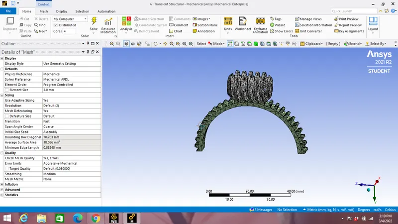
7)Boundary canditions:
a)Analysis settings:
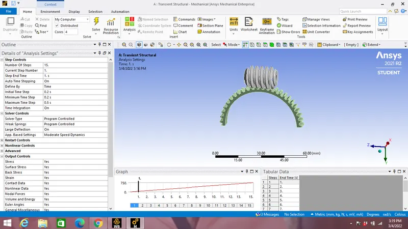
Number of steps taken for analysis is 15 with Intial time setup & Minimum time setup as 0.2 s with Maximum time setup as 0.5 s and all Output controls is switched On.
b)Joint rotation:
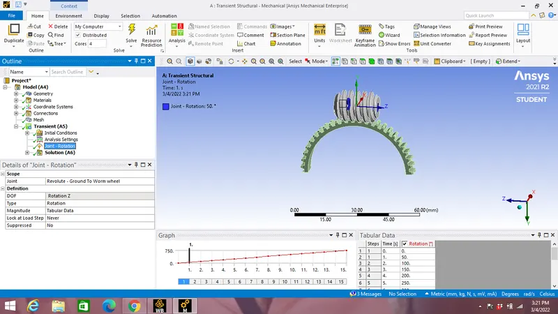
A joint rotation is applied in tabular format by selecting the revoulte joint of worm wheels as shown below:
Results:
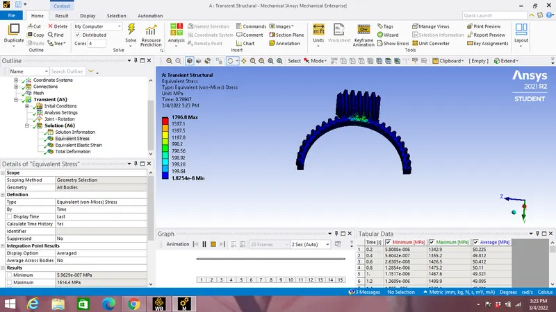
Equivalent stress:
Equivalent stress va time graph:
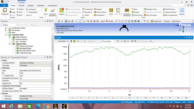
Maximum Equivalent stress:1796.8 MPa.
Equivalent Elastic strain:
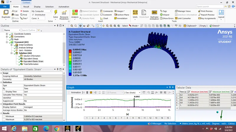
Equivalent Strain vs Time graph:
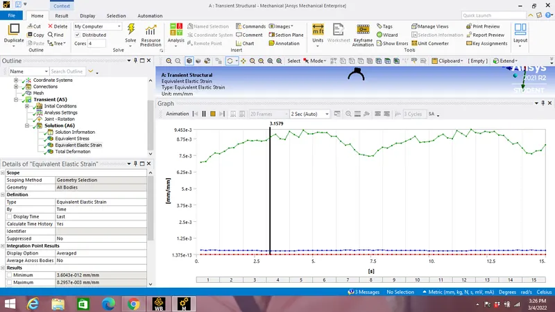
Maximum Equivalent Elastic Strain:0.009453
Total Deformation:
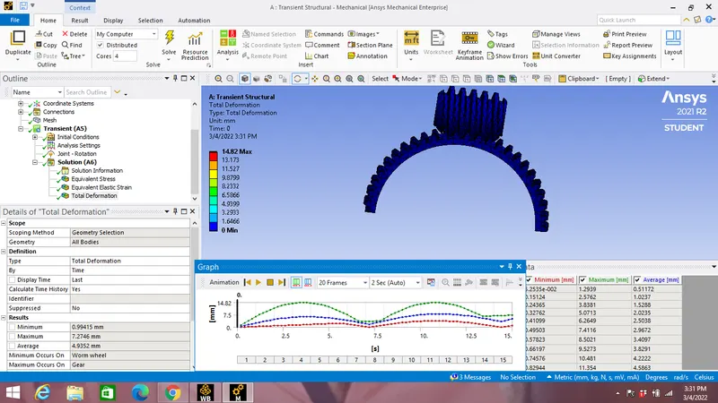
Total deformation vs time graph:
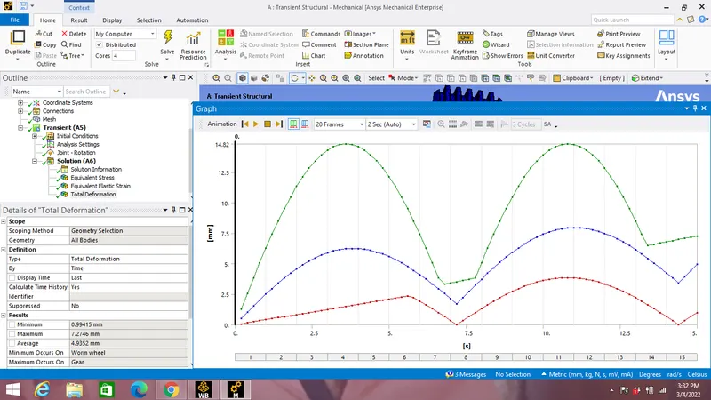
Maximum total deformation:14.32 mm.
Conclusion:
- Maximum Equivalent Stress & Strain are generated were gear & worm wheel teeths are in contact.
- Maximum total deformation happened on worm gear teeth.