Week - 5 - Modelling Spotwelds
Modelling Spotwelds challenge:
Aim: To model spotwelds for the given assembly of parts and run a crash test to compare axial and shear forces between the spotwelds made up of beam & solid elements of same material of spotweld.
Steps followed:
Case 1: Shell element for spotweld.
Import the model in .k format after downloading it as provided in the question above:
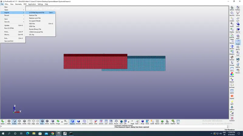
Take all units in gm,mm,ms.
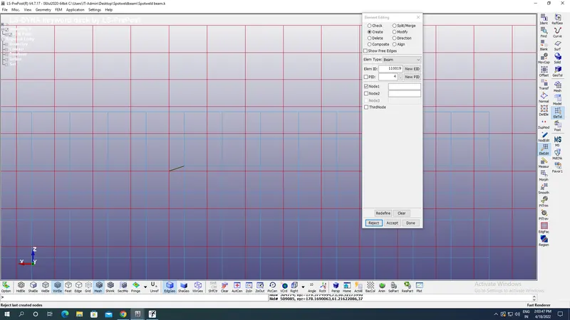
Create a 5 beam section connecting Top & Bottom plate with appropriate nodes selection on both plates from element edit option under element & tools by selcting Beam with one node from each sheet as shown in the image below:
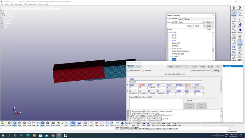
Create an appropriate section id for sheets with section id,element formulation as 16 which is fully integrated shell elements of thickness 1.5 mmas shown in the image below:
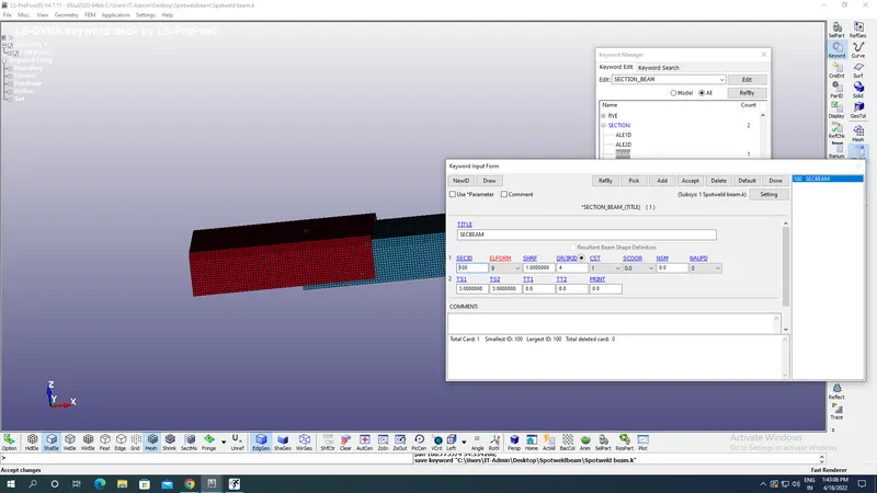
Similarly create a section for Beam element as well with appropriate ID,thickness as 3mm,element formulation & Quadrature as 4 as shown in the image below:
Now create an appropriate material for sheets & spotwelds.
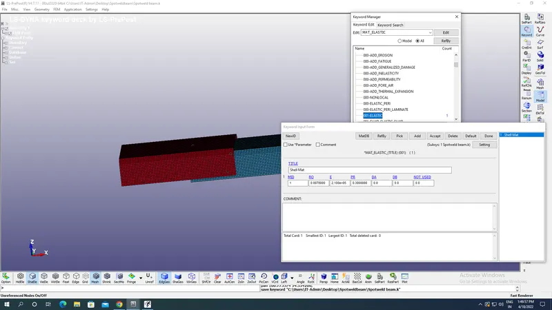
For sheets take 0001 Elastic material with steel material parameters as density 0.0078 gm/mm^3,Poission's ratio as 0.3,Young's modulus as 2.1E+05 gm/(mm ms^2) and Material ID.
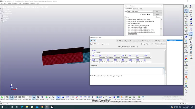
For Spotwelds take 100 Spotweld material with steel material parameters as density 0.0078 gm/mm^3,Poission's ratio as 0.3,Young's modulus as 2.1E+05 gm/(mm ms^2),Material ID,yield stresss(SIG y),Effective Plastic strain at failure (EFAIL),Axial resultant force,force resultant,force resultant at failure,Axial moments,Failure time as 2.0 ms etc as shown in the image below:
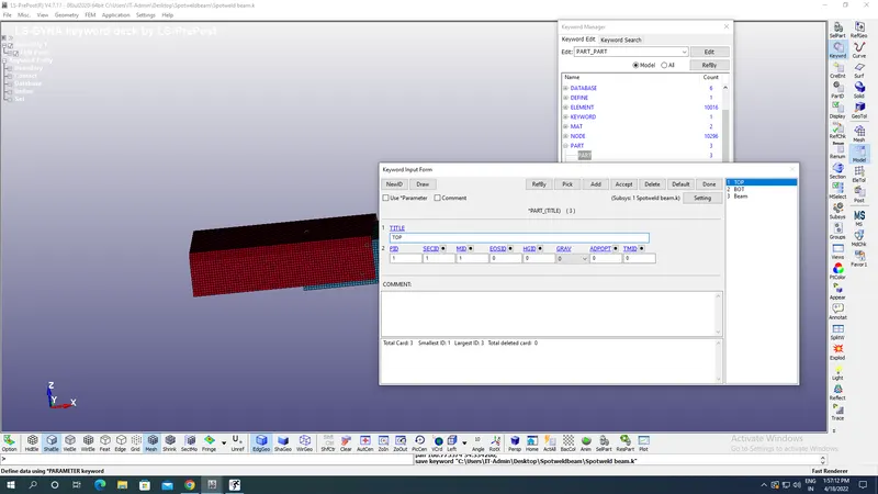
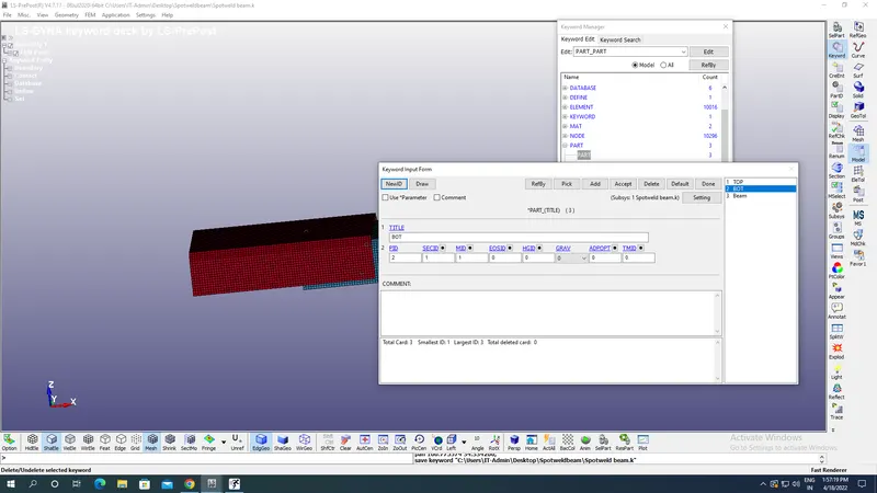
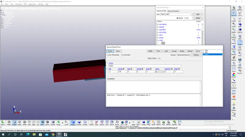
Now define parts with title,ID,Material ID,Section ID for Top,Bottom sheets & Beam elements as shown in the image below:
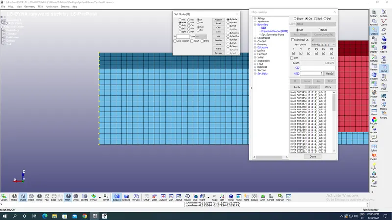
For boundary candition select the SPC under the create identity criteria ans select the area create a box withinin it all nodes selects are to be fixed as shown in the image below:
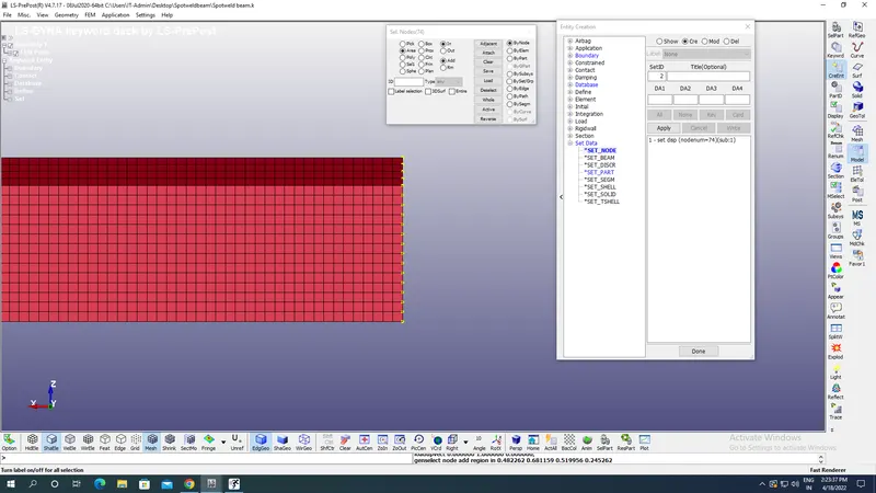
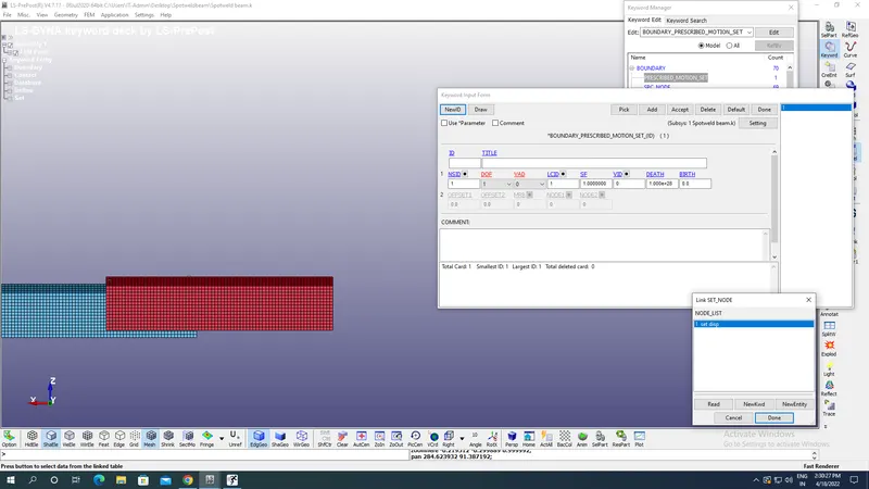
For Prescribed motion first create the set nodes & pick nodes under the box area with apprpriate name as set_disp as shown in the image below:
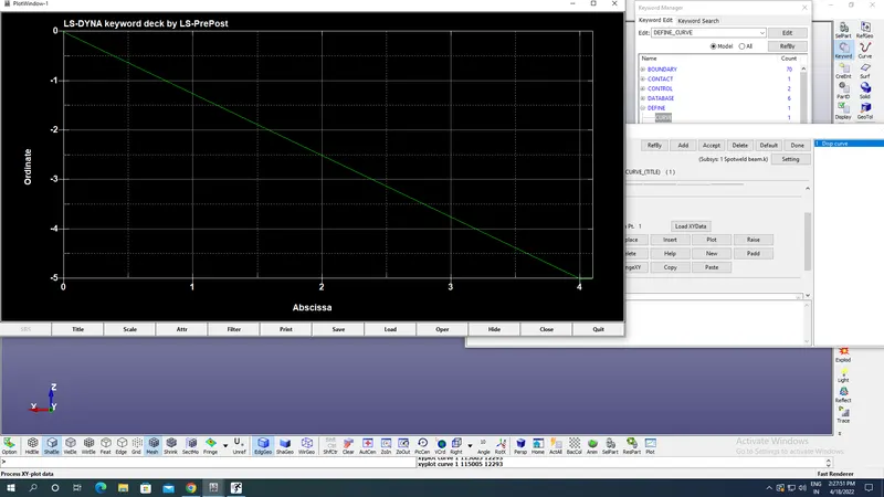
Now define the curve for velocity as shown in the image below along negative X axis translational as shown in the image below:
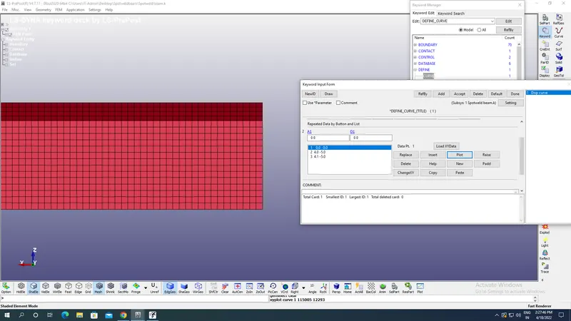
Plot of velocity vs Time of load curve with appropriate ID is shown in the image below:
Now Prescribed appropriate motion to the node with appropriate node selection & Load Id curve as shown in the image below:
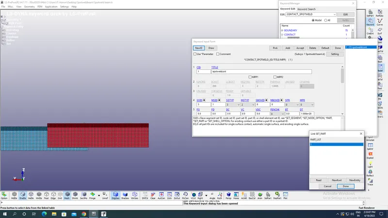
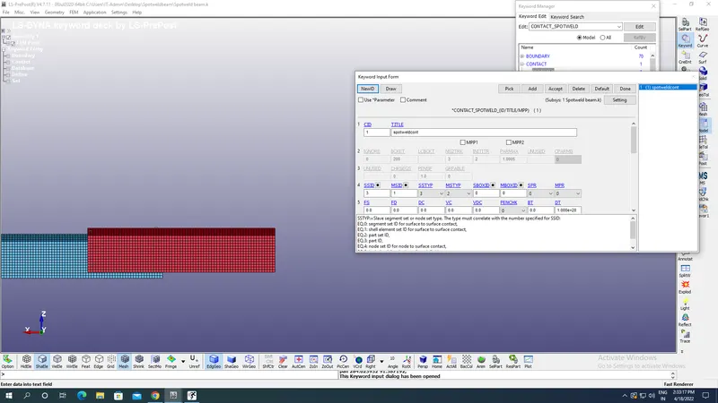
Now got to Contact & select the Spotweld with appropriate ID of master & slave set with slave set & master set segment as shown in the image below:
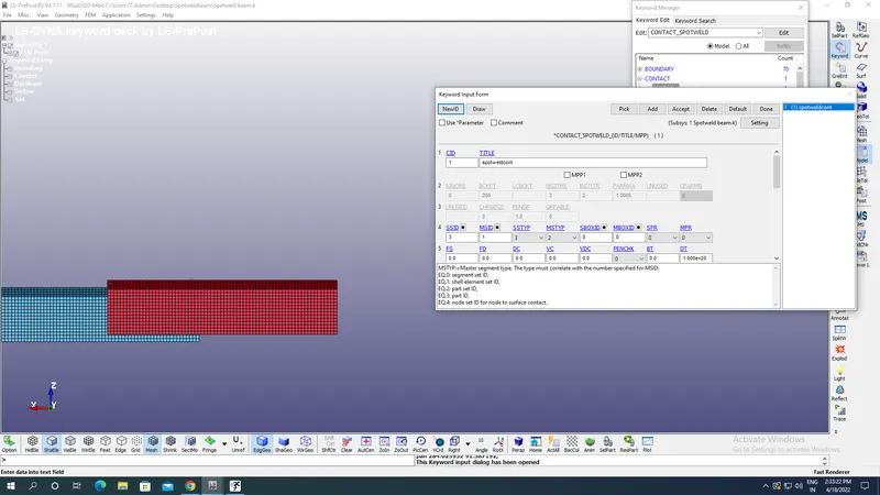
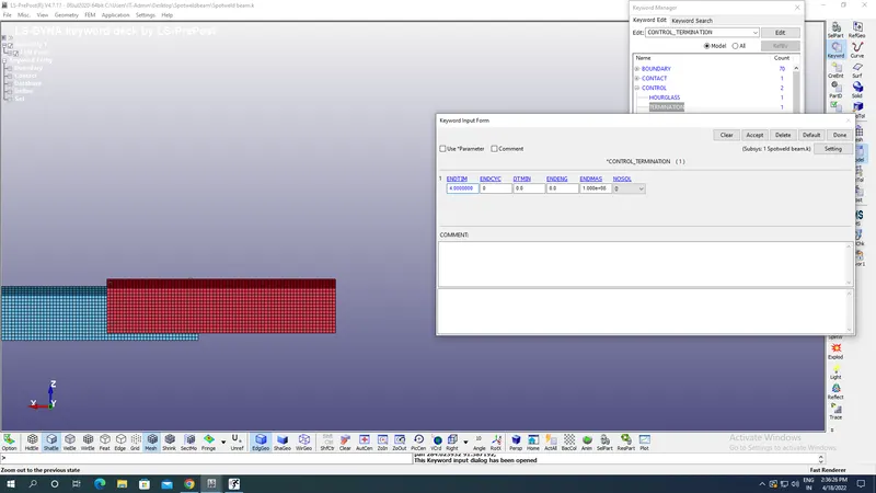
Now go to controls select Termination as 4 ms as shown in the image below:
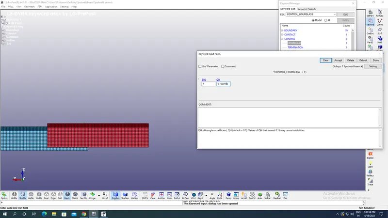
Select the hourglass in the Control with Hourglass Viscosity & coefficient as well:
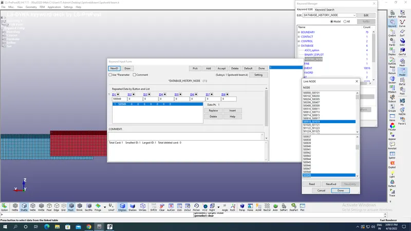
Now go to Database create the history node & select and input the desired node for output results on nodes as shown in the image below:
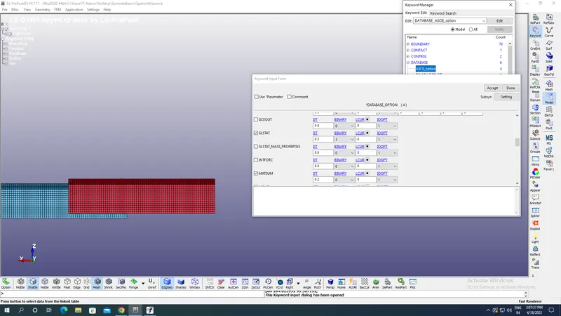
Define ASCII for GLSAT for recording energies,MATSUM for recording material energies by part,SWFORC for Spotweld force,NODEOUT for output at nodes with DT as 0.2 ms as shown in the image below: 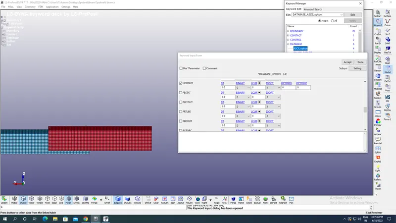
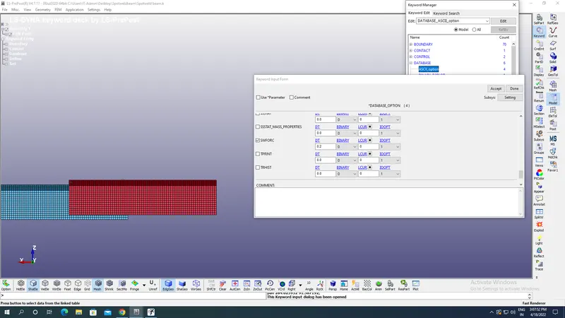
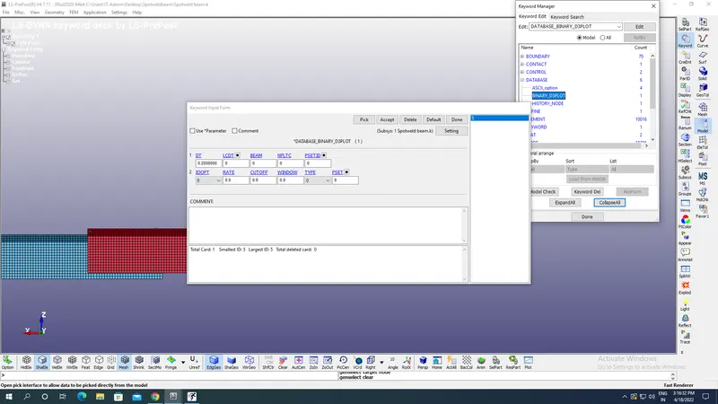
Define the Binary D3 plot as shown in the image below under Database option for the animation outputs with DT as 0.2 ms:
Case 2:
All other steps are same only beam part is deleted in Parts alongwith its section & under element & tools element edit option is selected with Hexa instead of Shell is chosen as shown in the image below:
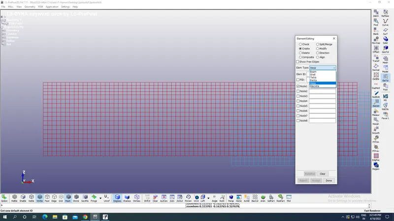
Select four nodes from elements of each sheet to create solid element as shown in the image below:
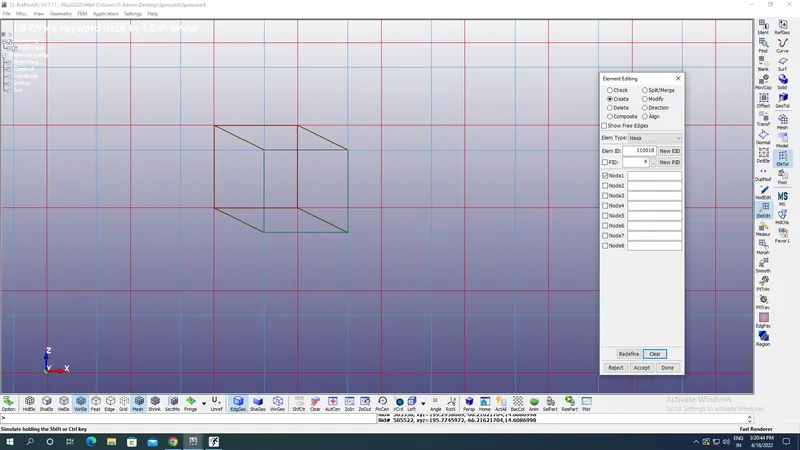
Simlarly create 5 solid element section connecting both the top & bottom sheets.
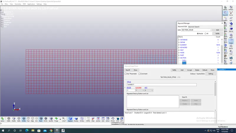
Now create section with appropriate section ID ,Title & element formulation as shown in the image below:
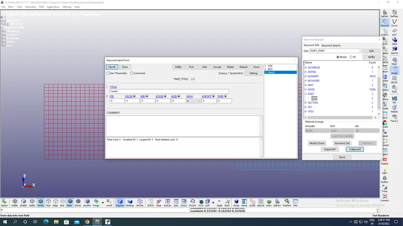
Create a part ID with material as 100 Spotweld same as before with approprite section ID assignes as shown in the image below:
All boundary canditions,termination time,Load curve & output plots remains same as in case 1.
Results:
Case 1:
X Directional stress:
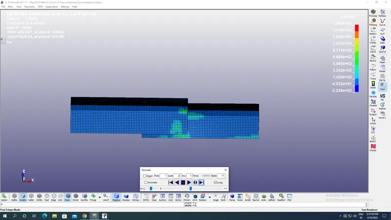
Maximum X directional stress is 1600 gm/(mm ms^2).
Y Directional stress:
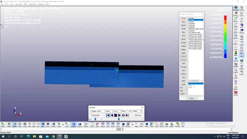
Maximum Y directional stress is 1479.28 gm/(mm ms^2).
Von mises stress:
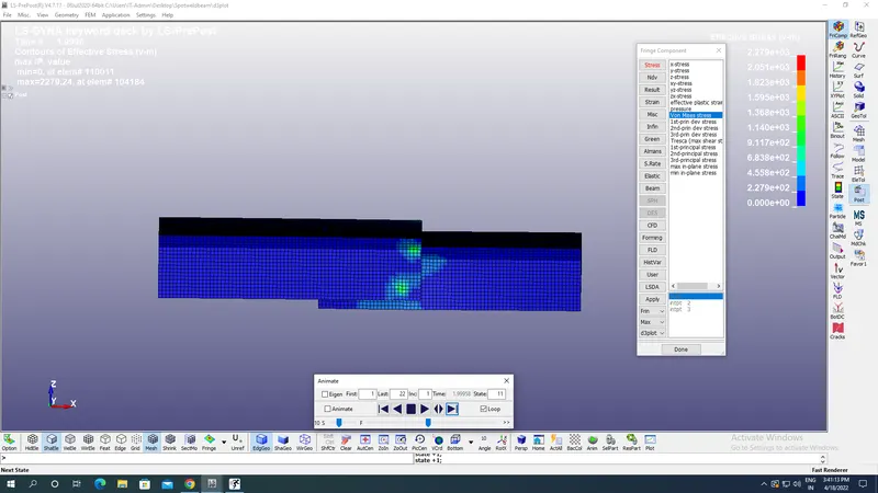
Maximum Von mises stress is 2279.24 gm/(mm ms^2).
Von mises strain:
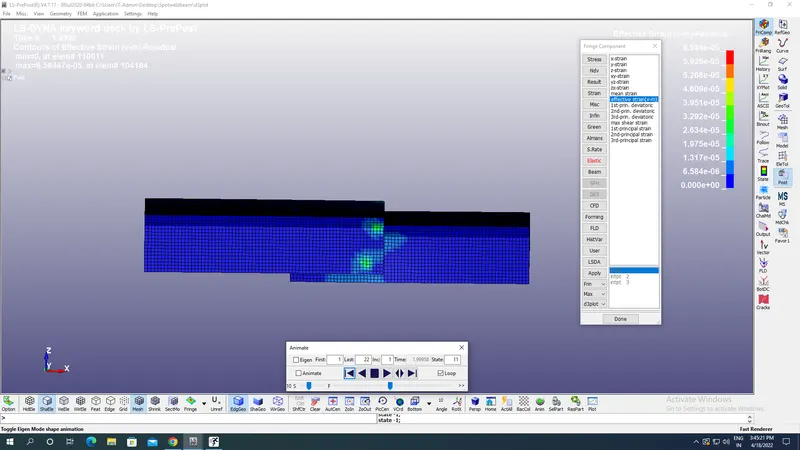
Maximum Von mises strain is 6.58 E-05.
Energy Plot from GLSAT including Kinetic,Total,Internal & sliding energies:
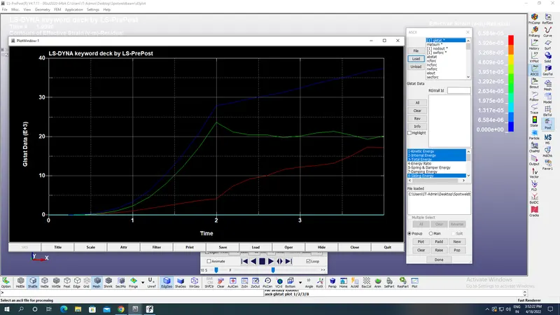
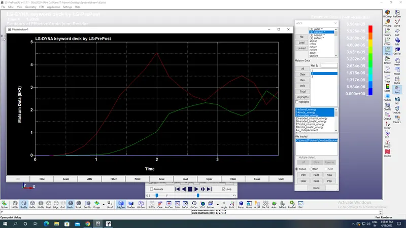
MATSUM plot for spote weld material including Kinetic,Total & Hourglass energies:
Nodal acceleration:
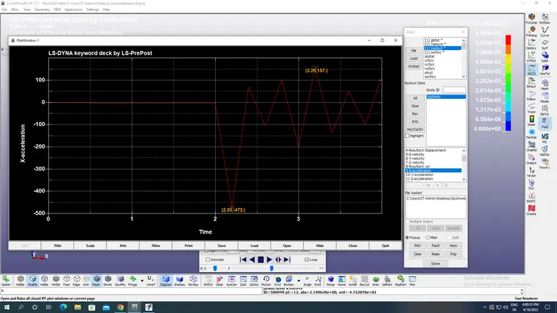
Maximum nodal retardation: 472 mm/ms^2.
Spotweld forces plot:
Axial force:
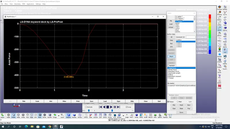
Maximum axial force on spotweld of beam element number 110012 is 405 gm mm/ms^2 along negative X axis..
Shear force:
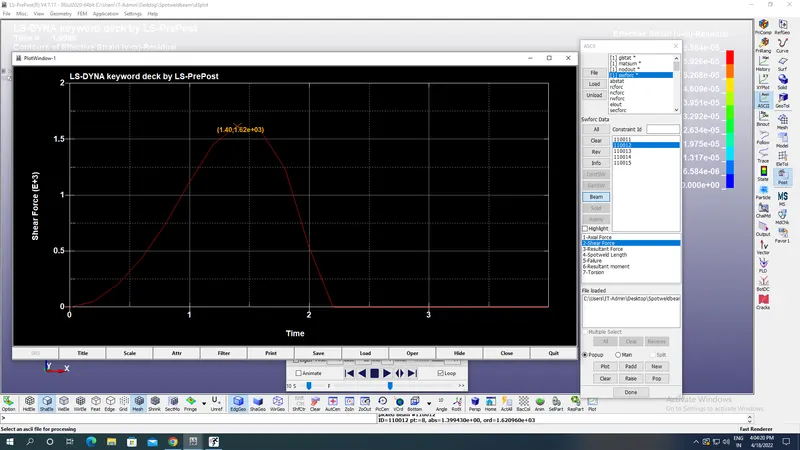
Maximum shear force on spotweld of beam element number 110012 is 1.62E+03 gm mm/ms^2 along Y axis.
Failure plot on spotweld:
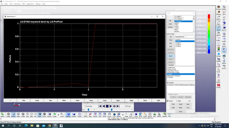
Case2:
X Directional stress:
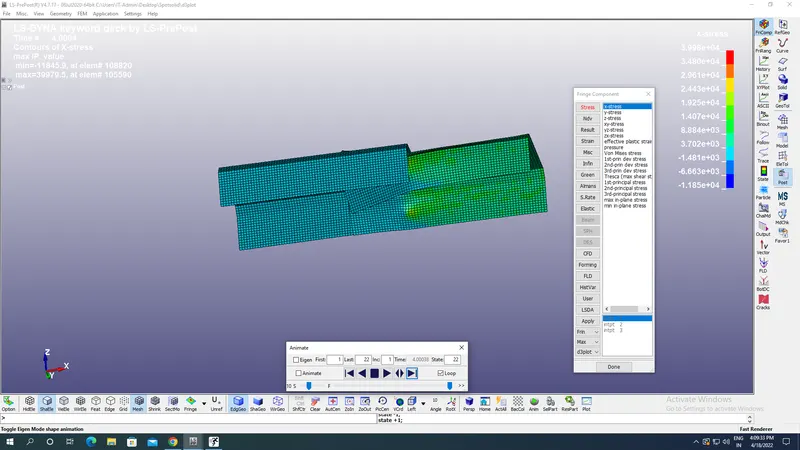
Maximum X directional stress is 39979.5 gm/(mm ms^2).
Y Directional stress:
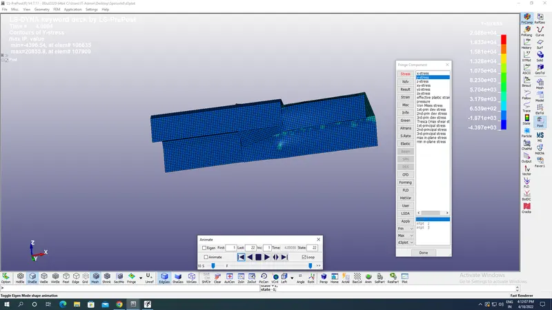
Maximum Y directional stress is 20855.28 gm/(mm ms^2).\
Von mises stress:
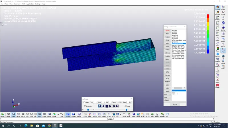
Maximum Von mises stress is 35966.24 gm/(mm ms^2).
Energy Plot from GLSAT including Kinetic,Total,Internal & sliding energies:
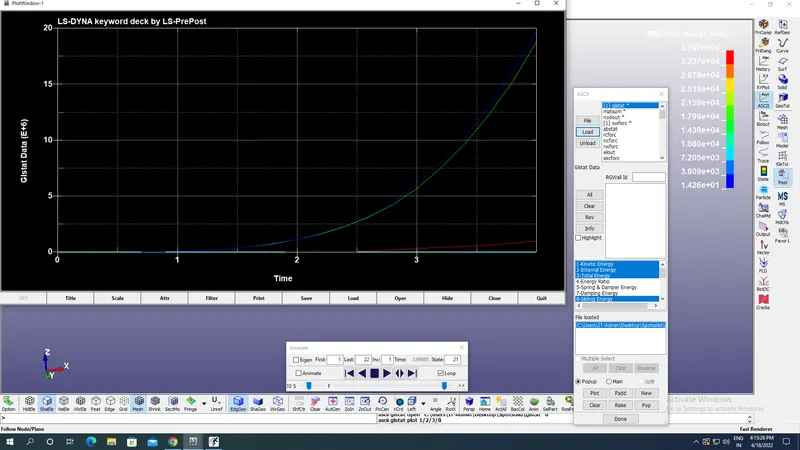
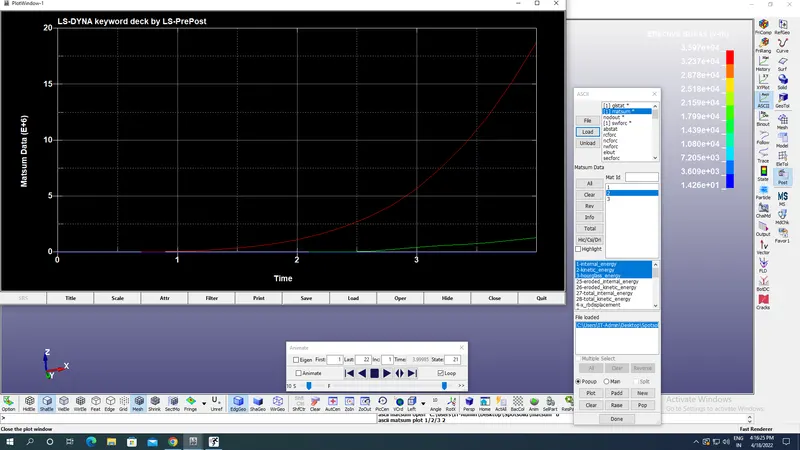
MATSUM plot for spote weld material including Kinetic,Total & Hourglass energies:
Nodal acceleration:
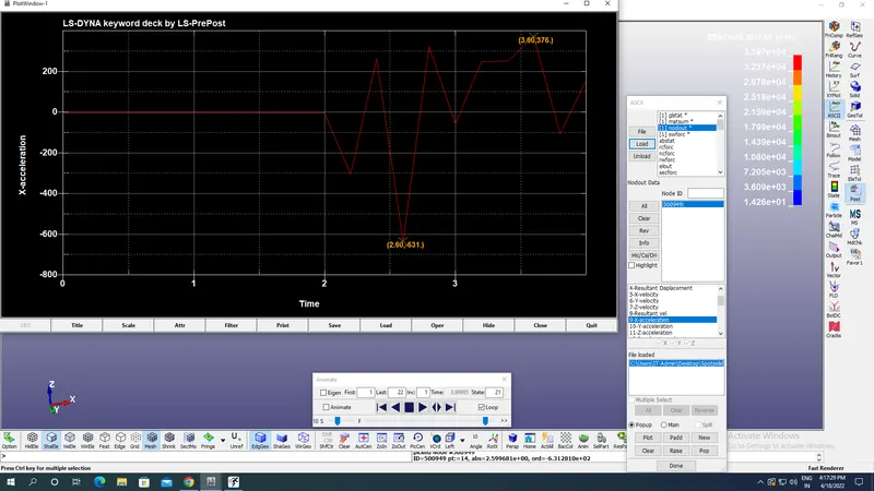
Maximum nodal retardation:631 mm/ms^2.
Spotweld forces plot:
Axial force:
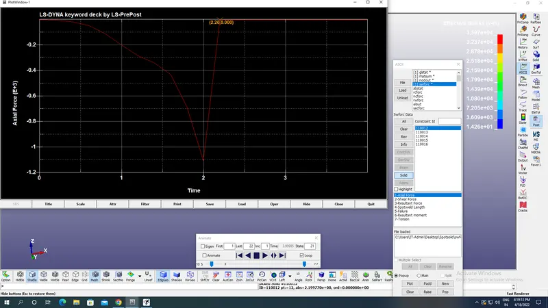
Maximum axial force on spotweld of Solid element number 110012 is 1.11E+03 gm mm/ms^2 along negative X axis.
Shear force:
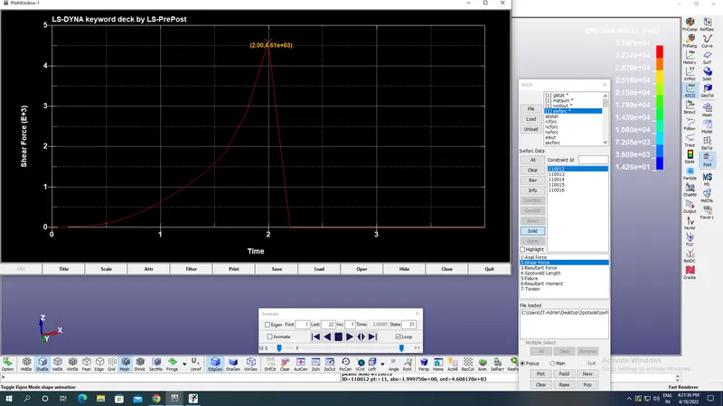
Maximum shear force on spotweld of solid element number 110012 is 4.61E+03 gm mm/ms^2 along Y axis.
Failure plot on spotweld:
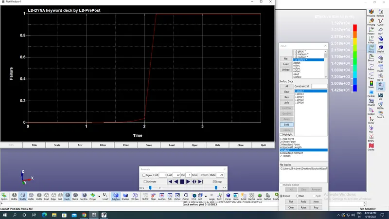
Comparison of Beam & Solid elements:
| Maximum Von mises stress(gm mm^-1 ms^-2) | Maximum Axial force(gm mm ms^-2) on spotweld | Maximum Shear force(gm mm ms^-2) on spotweld |
Nodal retardation (mm/ms^2) |
|
| Beam element | 2279.24 | 405 | 1.62E+03 | 472 |
| Solid element | 35966.24 | 1.11E+03 | 4.61E+03 | 631 |
We can observe from the comparision table above that nodal retardation due to solid element connection betwen the two sheet is more than due to 1D Beam element connection at the same time Maximum Von Mises stress due to solid elements is more than beam elements of same 100 Spotweld material so failure of Beam element is easier than solid element.
Axial force on the solid element is more while shear force on the beam element is more.
Conclusion:
The solid Hexa8 element is connected by 8 nodes at each sheet, while Beam element is connected by 2 nodes at each sheet so it is easier to deform beam elements by displacement of 2 connecting node while Hexa8 element can be deformed only when 4 nodes move at sufficient distance apart from the other 4 nodes of other sheet, so for same material 100 Spotweld, the Von mises stress is high in Hexa8 compared to beam element.
Axial force is also high for solid elements again beacuse 4 nodes at each sheet must be moved to axially away from other 4 nodes before failure while that for beam element only 2 nodes movement is enough along axial direction to fail the element.
At the same time we have axial stiffness for solid element which is EA/L which resists the deformation.So its natural that solid element must have higher axial force compared to beam elements before there failure.