Project 3- Study of cantilever beam with different cross-sections like circular, rectangular and I section and to find out the effect of cross-section on the deflection of the beam using FEA technique using Ansys Workbench and results has to be verified using strength of material deflection equations.
Study of cantilever beam with different cross-sections like circular, rectangular and I section and to find out the effect of cross-section on the deflection of the beam using FEA technique using Ansys Workbench and results has to be verified using strength of material deflection equations:
Aim: Study of cantilever beam with different cross-sections like circular, rectangular and I section and to find out the effect of cross-section on the deflection of the beam using FEA technique using Ansys Workbench and results has to be verified using strength of material deflection equations.
Procedure:
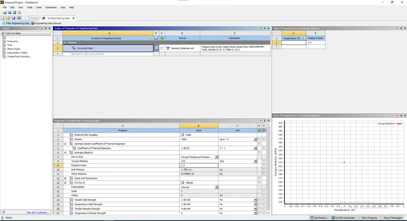
- Structural steel is choosen as a material for all the three different shapes with material parameters as shown in the image below:
Geometry:
Circular cross section:
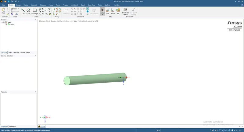
- A circle of radius 50 mm is drawn and extruded in 3D with 1000 mm length as shown in the image below:
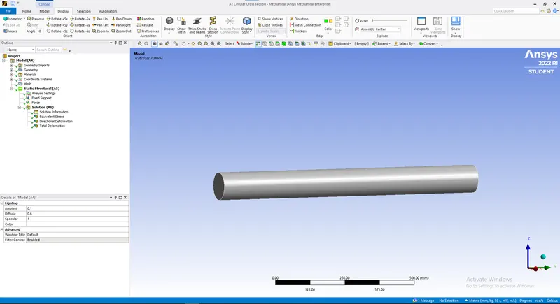
- Now update the model tree and try opening it as shown in the image below:
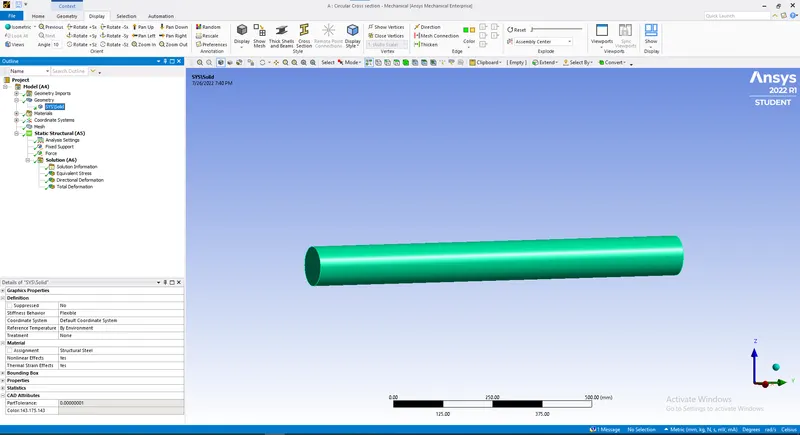
- Structural steel is assigned to the geometry as shown in the image below:
- Mesh size of 10 mm is applied to the body:
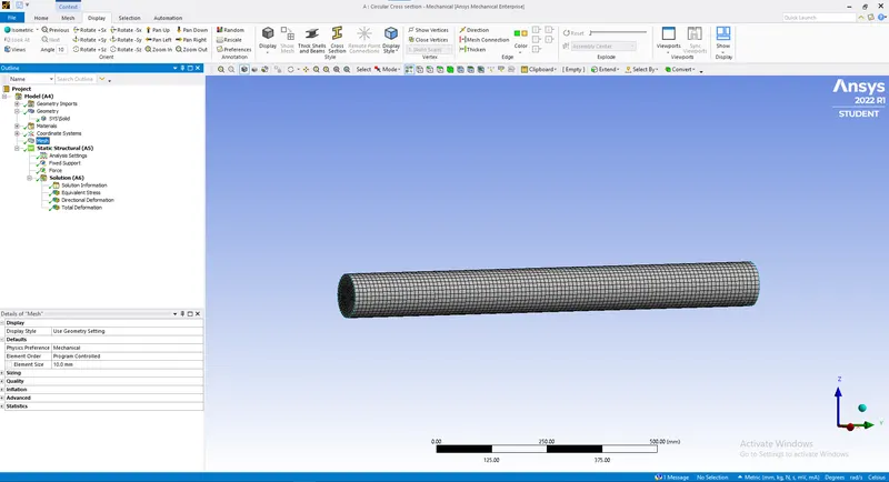
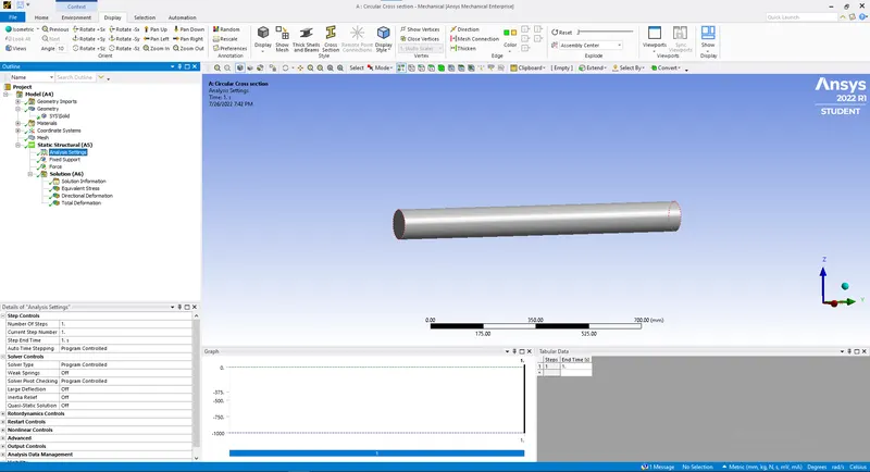
- Analysis setting is kept as default as shown in the image below:
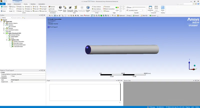
- Boundary canditions:
A Fixed support is applied by selecting the one end face of the body as shown in the image below:
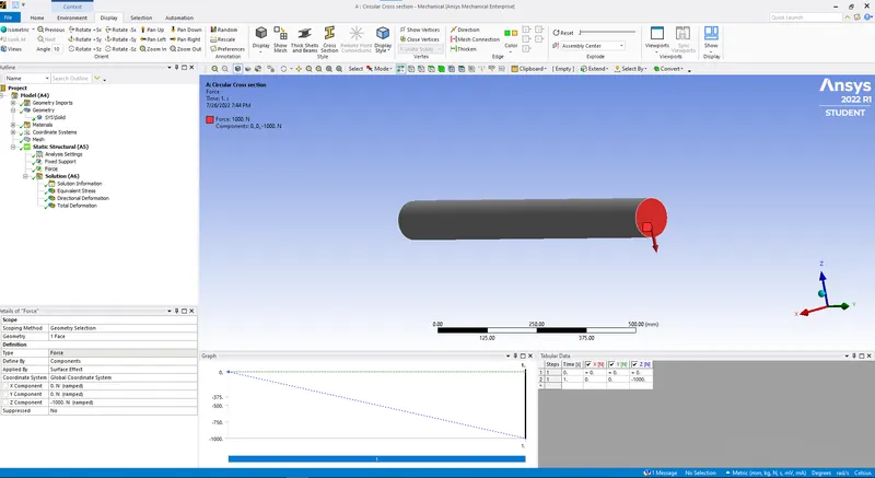
A load of 1000N is applied to the opposite face along negative Z axis as shown in the image below:
Results:
Total deformation:
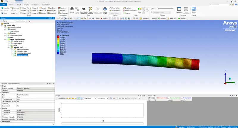
Maximum total deformation:0.32405mm
- Geometry:
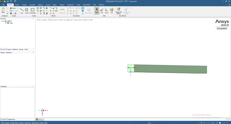
A rectangle of 50x50 `mm^2` is drawn and extruded to the length of 1000 mm as shown in the image below:
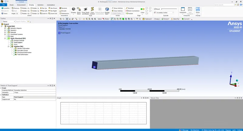
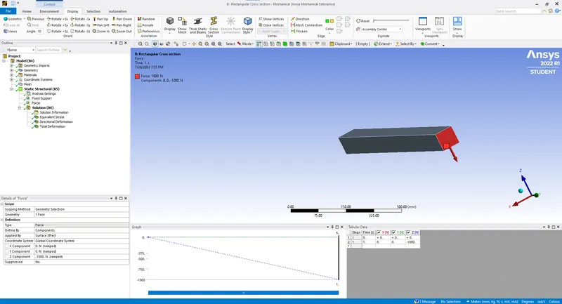
Material assignment,meshing boundary candition everything is similar as above alongwith the direction of load of 1000N applied along negative Z axis:
Results:
Total deformation:
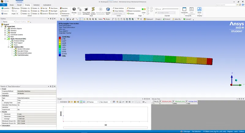
Maximum total deformation:3.0422mm
- Geometry:
An I section is created with Area equal to the area of the rectangular cross section of 50x50 `mm^2` with dimensions as 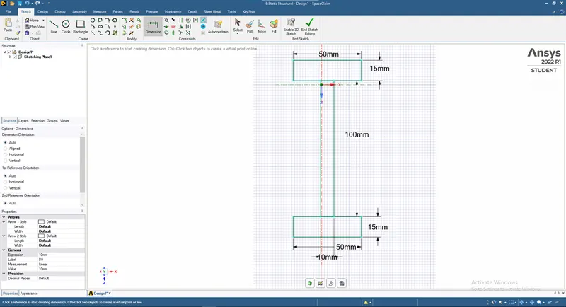
Then Merge faces are used to merge various rectangles and finally extruded with 1000 mm length:
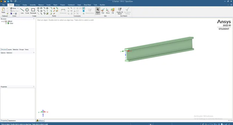
Material assignment,meshing boundary candition everything is similar as above alongwith the direction of load of 1000N applied along negative Z axis:
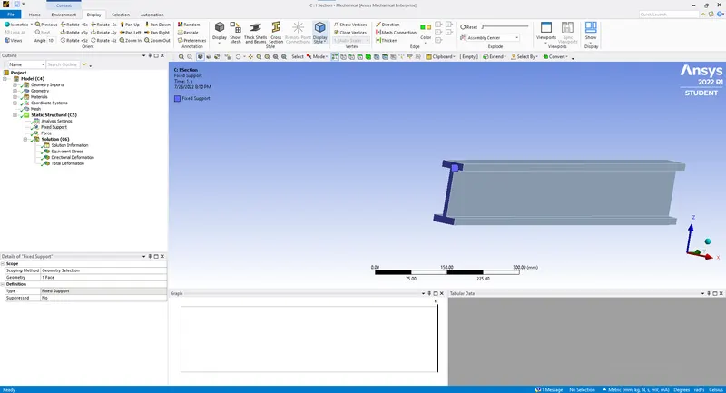
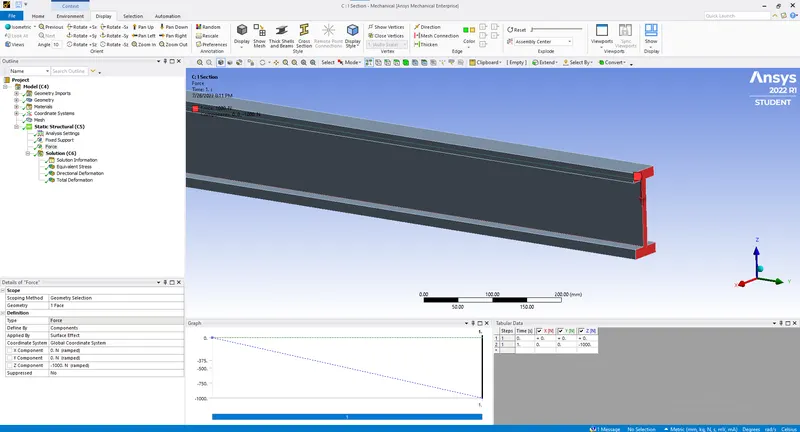
Results:
Total deformation:
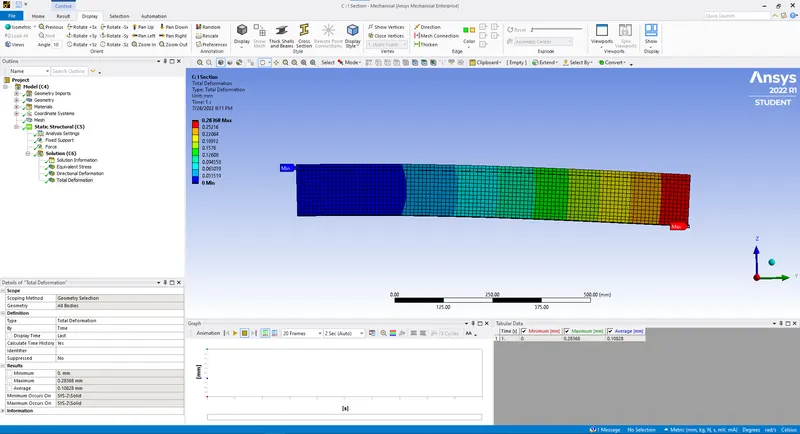
Maximum total deformation:0.28368mm.
Results verification by Analytical method:
Now the deflection is calculated by Strain energy method of Strength of materials concept:
Strain energy(U)=`1/(2EI)int_0^L (M_x)^2 dx`=`P/2*delta`
Were `M_x` is bending moment of Cantilever Beam E is Young's Modulus(E)=210000MPa I is Area Moment of Inertia about axis of deformation which is along X in all three geometrical figures, P is load of 1000 N while & `delta` is deflection.
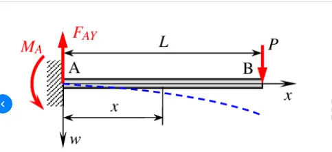
Now Bending Moment for Cantilever Beam with load(P) as 1000 N at the free end when seen from the right side i.e along free end at negative Zaxis: (`(-1000*x`)
Circular cross section:
Moment of Interia about axis of Bending i.e. Neutral axis is(`I_N`) for circular cross section=`pi/64d^4`,
Were d is diameter of circle=100mm.
Moment of interia of circle about `I_x`=4908738.52`mm^4`
Strain energy(U) in case of circular cross section `1/(2EI)int_0^L (M_x)^2 dx`=161.68121N mm
`delta=161.681212*2/1000=00.323362424 mm`
So the value of deflection what we got from FEA analysis was 0.32405mm which is close to the real value by Analytical approach in case of circular cross section.
Rectangular cross section:
Moment of Interia about axis of Bending i.e. neutral axis is(`I_N`) for rectangular cross section=`b.l^3/12`,
Were b=l=50 mm is the length & width of rectangular cross section.
Moment of interia of rectangle about `I_N`=520833.333`mm^4`
Strain energy(U) in case of rectangular cross section `1/(2EI)int_0^L (M_x)^2 dx`=1523.80952N mm
`delta=1523.8052*2/1000=3.047 mm`
So the value of deflection what we got from FEA analysis was 3.0422mm which is close to the real value by Analytical approach in case of rectangular cross section.
I section:
Area of top & bottom rectangles(A)=`50*15=750 mm^2`
Distance of centroidal axis of Top & bottom rectangles from neutral axis(x)=`50+7.5=57.5 mm`
Now By Parallel Axis Theorem we get Area moment of Inertia of Top & Bottom rectangles:`I_c+A*x^2`
Moment of Interia about axis of Bending i.e. neutral axis is(`I_N`) for two rectangular cross section at the top & bottom of I section=`2*(b*h^3/12+A*x^2)+B*H^3/12=582833.33mm^4`
Were b=50mm,l=15mm of top & bottom rectangles while B=100 mm & L=10 mm for the middle rectangle about which neutral axis passes is the length & width of varoius rectangular cross sections.
Moment of interia of I section about its neutral axis=582833.333`mm^4`
Strain energy(U) in case of I section `1/(2EI)int_0^L (M_x)^2 dx`=136.3465930395N mm
`delta=136.3465930395*2/1000=0.27269 mm`
So the value of deflection what we got from FEA analysis was 0.28368 mm which is close to the real value by Analytical approach in case of I section.