Week - 4 - Crash Box Simulation
Crash Box Simulation:
Aim:
Simulation of a crash test for a crash box on a rigid wall for which mesh is given & steel material is taken with elstic material properties.
Steps followed:
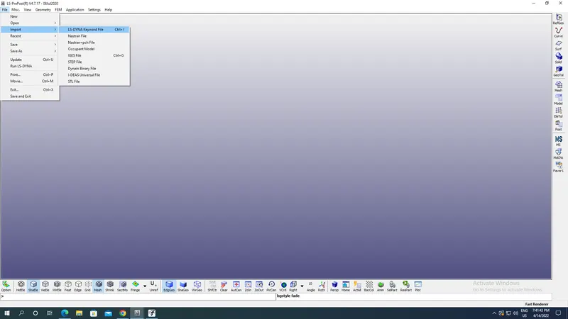
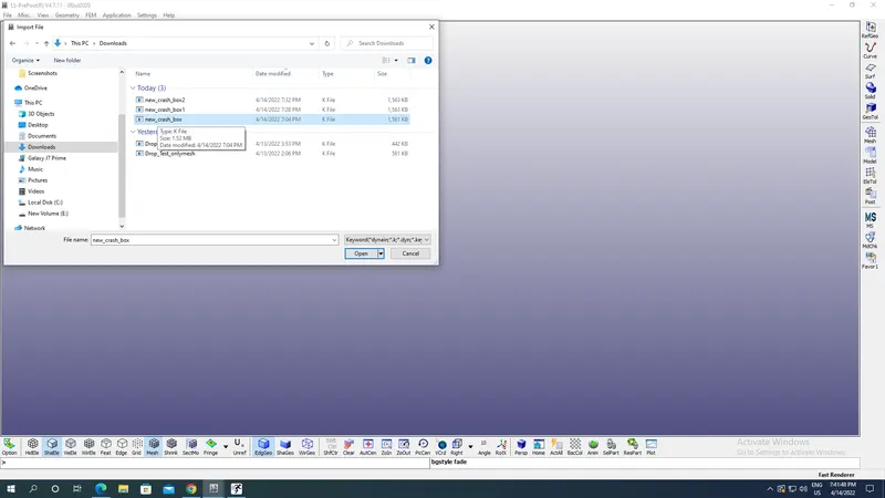
Import the file containg model of box to be crashed under file option-LS Dyna Keyword file in .k format as shown in the image below:
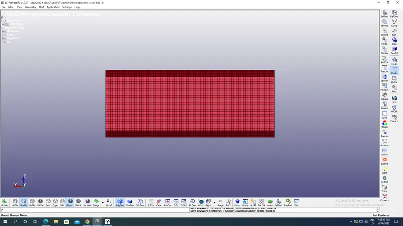
Imported model appears with meashing appears as:
Now go to Model option under it select the Keyword option to input our data required such as sections,materials,rigidwall,velocity etc:
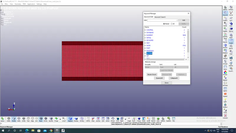
Note: All units here are taken in gm,mm,ms.
Case 1: For 1.2 mm shell thickness of box section:
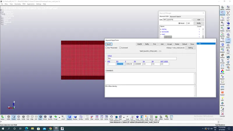
First we are creating material for the box under MAT option with density as 0.0078 gm/mm^3,Young,s modulus=2E+05 gm/(mm ms^2) and Possion's ratio as 0.2 which is Steel here with Elastic material property with appropriate material Id as shown in the image below:
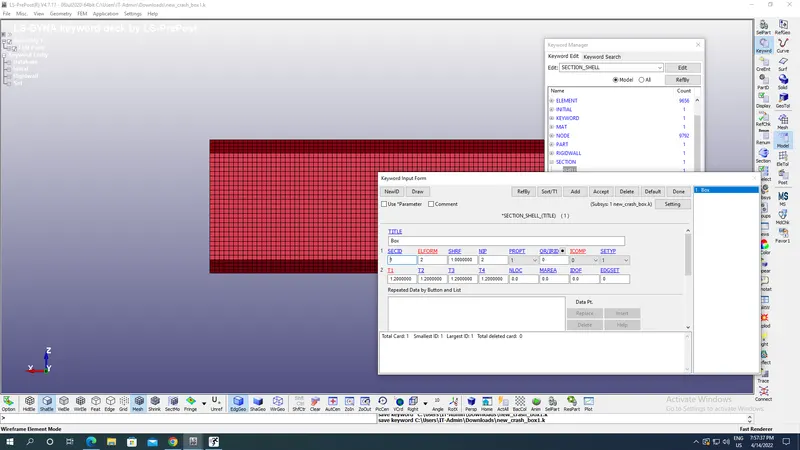
Create section under Section option with Shell type with thickness as 1.2mm of shell with section id as shown in the image below:
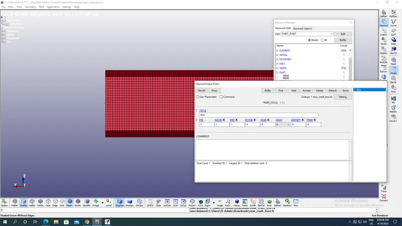
Go to part assign appropriate material id,section id & part id as shown in the image below:
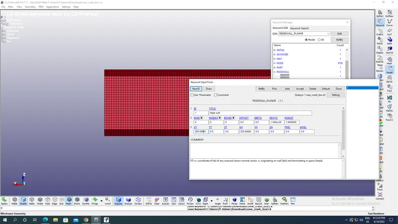
Now apply rigid wall under RigidWall option with appropriate X coordinate Tail & Head such that it is along the direction of stress propogation which is here for Tail as 260 mm & for Head it is 255 mm along negative X axis i.e along length of box with appropriate ID of Rigid wall as shown in the image below:
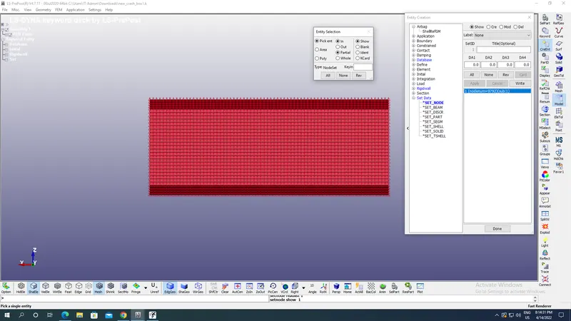
Create a set of nodes for applying intial velocity to the nodes of box with create entity option-Set Node as shown in the image below & select all the nodes as shown in the image below:
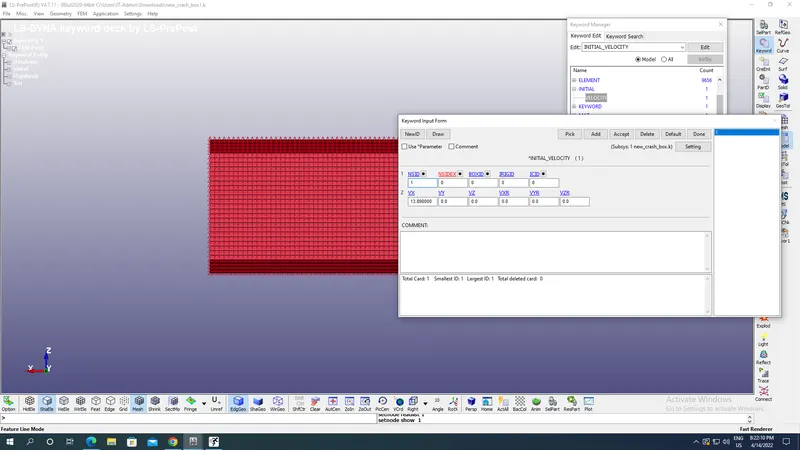
Apply intial velocity of 13.89 mm/ms along positive X axis by selecting Intial-Velocity and the set ID which is cretaed above as shown in the image below:
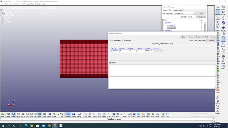
Go to Control keyword & select the control terimination time as 1 ms as shown in the image below:
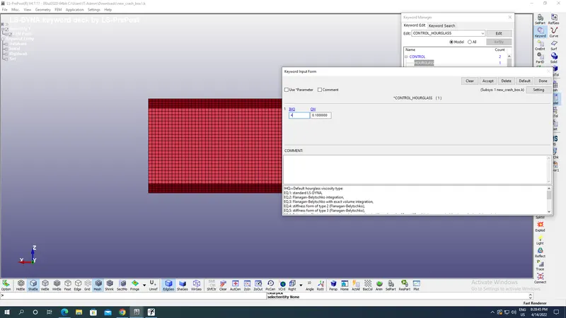
Select the Hourglass under Contact option with appropriate hourglass coefficient & hourglass viscosity coefficients as shown in the image below:
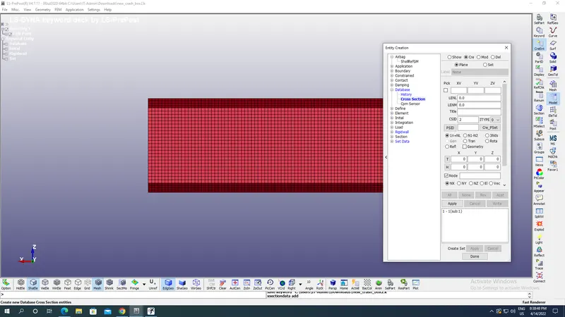
Go to Create entity select the appropriate node and apply Cross Section under DATABASE such that its normal is along X axis as shown in the image below:
For acceleration select the same node which had been selected for the cross section under create entity-Database-History as shown in the image below:
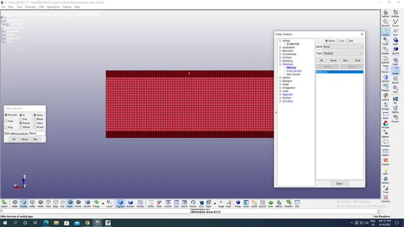
Node ID above selected node is 8115.
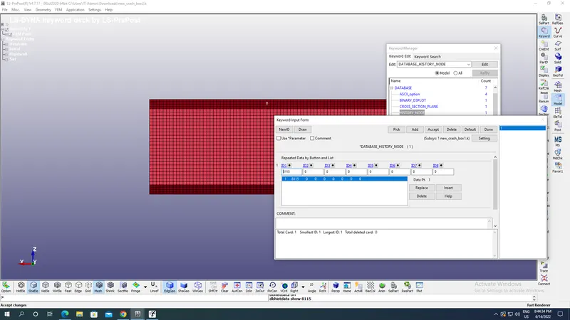
Now go to Database for outputs, select Node History option with Node ID for node acceleration as shown in the image below
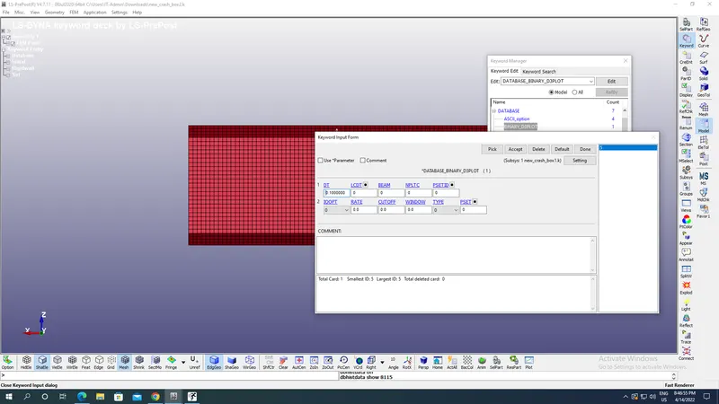
Similarly assign Binary D3 Plot as shown in the image below with DT as 0.41 ms:
Similarly assign ASCII plot as shown in the image below with DT as 0.01 frequency:
MATSUM,GLSAT,SECFORC,NODEOUT as per requirments:
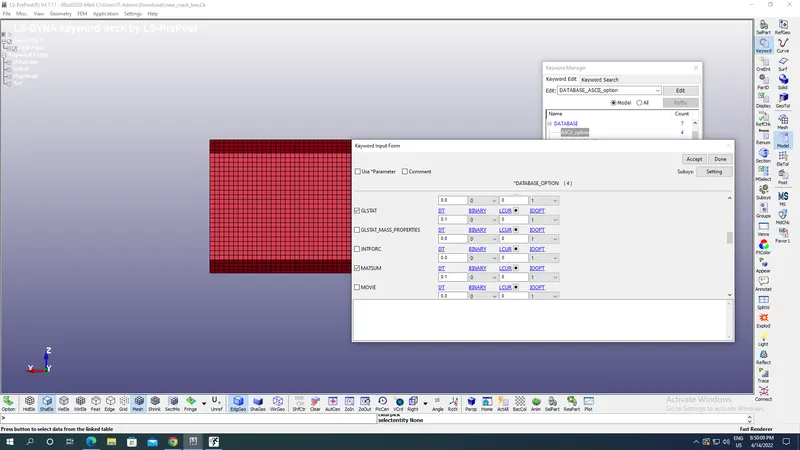
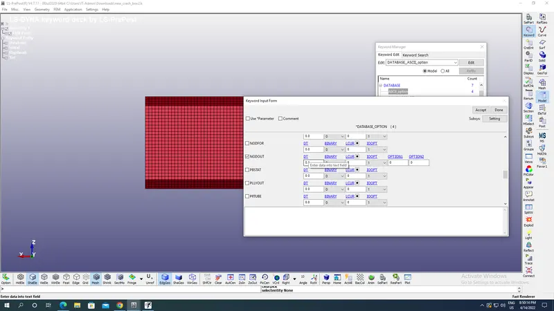
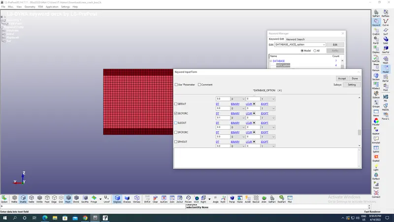
Now save it underFile-Save as-Save Keyword as,Run the file under LS Run option under file menu.
Case 2: For 1.5 mm shell thickness of box section:
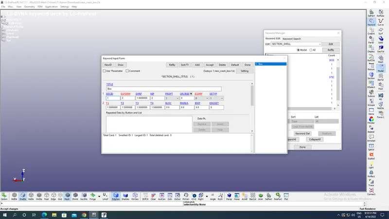
All the steps are same as in case 1 only in section-shell thickness hanged to 1.5 mm as shown in the image below:
Results:
Case 1:
d3plots:
Directional Stress along X axis:
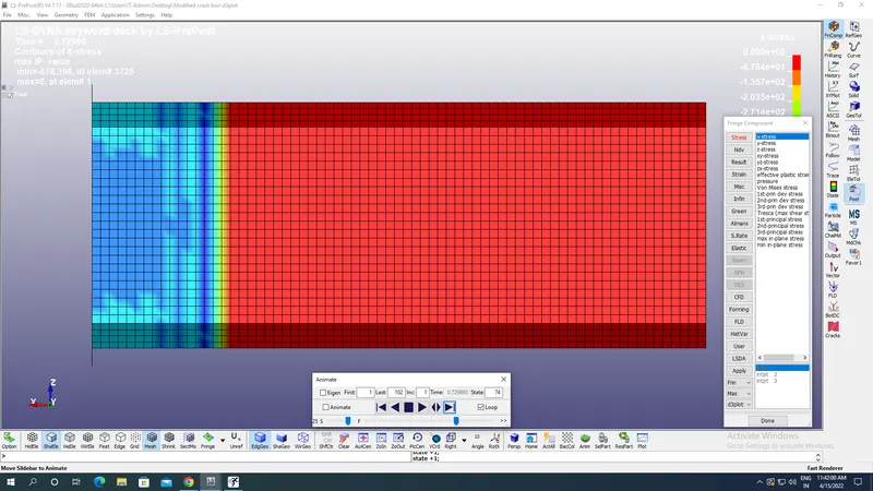
Maximum Directional stress along X axis for 1.2mm shell thickness of section:-678.398 gm/(mm ms^2 i.e compression stress.
Directional Stress along Y axis:
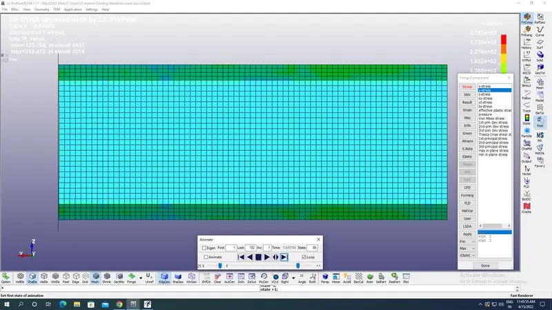
Maximum Directional stress along Y axis for 1.2mm shell thickness of section:318.472 gm/(mm ms^2) i.e compression stress.
Von mises stress:
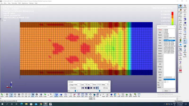
Maximum Von mises stress on the box:670.0695 MPa.
Directional strain along X axis:
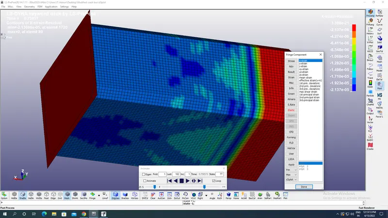
Maximum directional strain:-2.13E-05 along X axis.
Directional strain along Y axis:
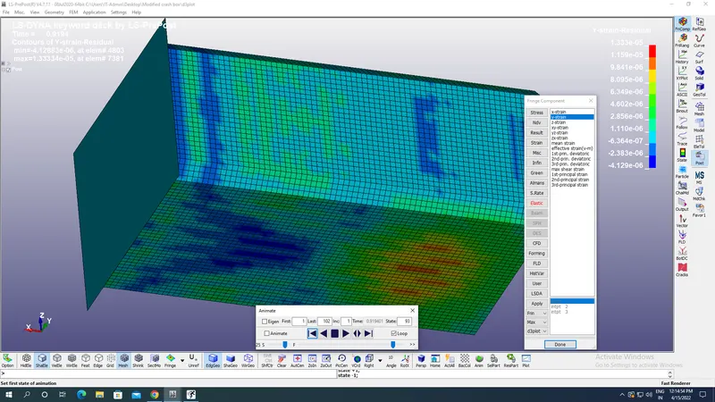
Maximum directional strain:1.33E-05 along Y axis.
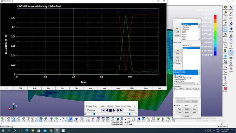
GLSAT for recording various kinds of energies which are Kinetic,Total,Internal & Sliding energy as plotted in the time graph below:
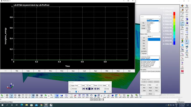
MATSUM Plot for recording material energies due to deformation which here are Hourglass energy here:
Nodal accelration along length of box:
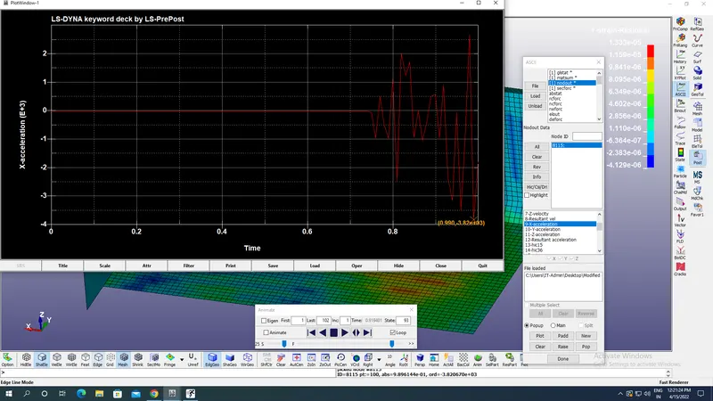
Maximum retardation achieved after impact is-3.8 E+03 mm/ms^2.
Sectional force on the box middle surface along length:
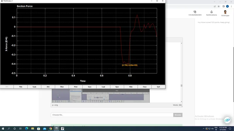
Maximum force in the section is 4E+05 gm mm/ms^2 along negative X axis i.e along length of box.
Case 2:
d3plots:
Directional Stress along X axis:
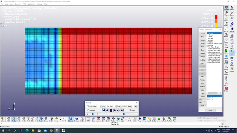
Maximum Directional stress along X axis for 1.5mm shell thickness of section:-582.294MPa i.e compression stress.
Directional Stress along Y axis:
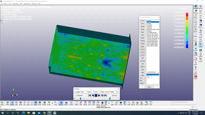
Maximum Directional stress along Y axis for 1.5mm shell thickness of section:-251.4MPa i.e compression stress.
Von mises stress:
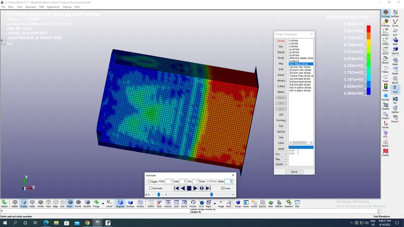
Maximum Von mises stress on the box:671.096MPa.
Directional strain along X axis:
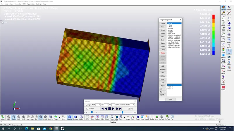
Maximum directional strain:4.3277E-06 along X axis.
Directional strain along Y axis:
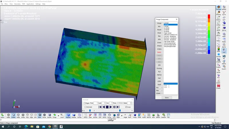
Maximum directional strain:7.95544E-06 along Y axis.
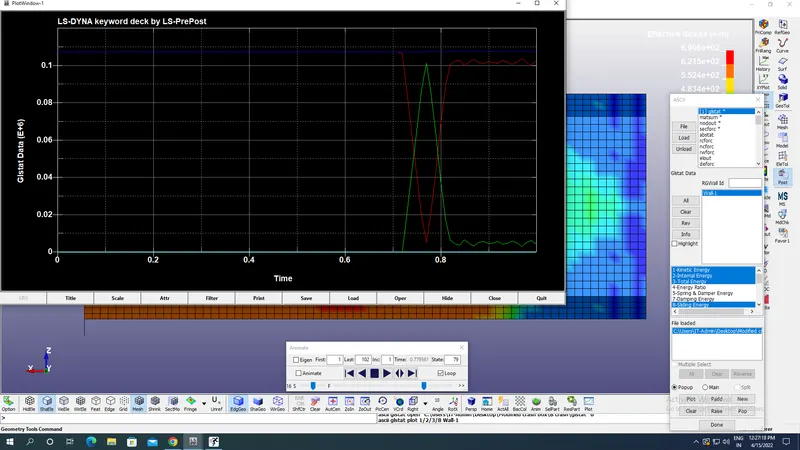
GLSAT for recording various kinds of energies which are Kinetic,Total,Internal & Sliding energy as plotted in the time graph below:
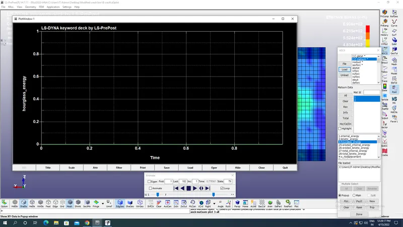
MATSUM Plot for recording material energies due to deformation which here are Hourglass energy:
Nodal acceleration along length of box:
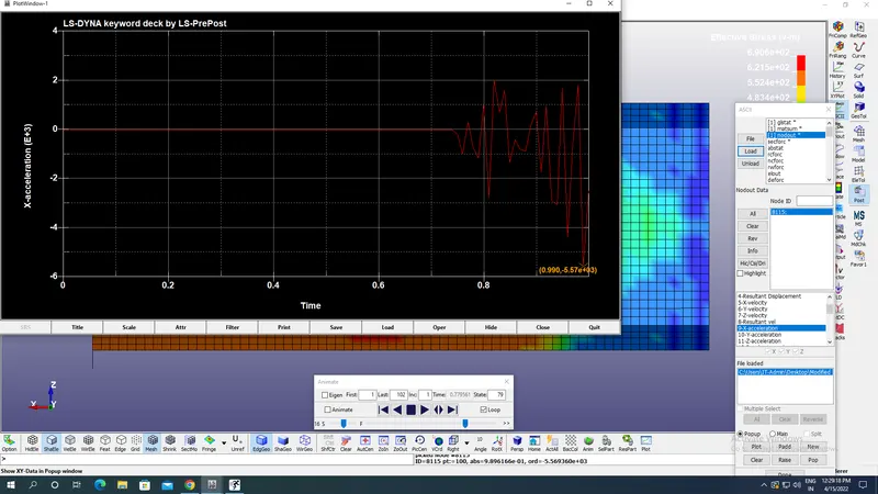
Maximum retardation achieved after impactis between 5.57 E+03 mm/ms^2 along negative X axis.
Sectional force on the box middle surface along length:
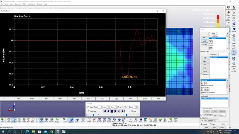
Maximum sectional force is close to 3.18E+05gm mm/ms^2 at 0.8 ms as seen from image above:
Comparision:
| Shell thickness(mm) | Maximum Von mises stress(gm mm^-1 ms^-2) | Maximum Retardation(mm/ms^2) |
| 1.2 | 690.54 | 4E+05 |
| 1.5 | 671.723 | 5.57 E+03 |
Conclusion:
- From the comparision table it is clear that maximum Von Mises stress decreases due to increase in shell thickness of section from 1.2 mm to 1.5mm because as the thickness keeping the same material the cross sectional area increases keeping the restoring force same so stress decreases.