Assignment 1-2D Meshing Challenge
2-D Meshing Challenge:
Aim:
- Carryingout the geometry cleanup operation.
- Extract midsurface.
- Clean midsurface geometry.
- Ignore holes less than dia 5mm.
- Create 2D mesh with target length 5mm, min 3.5mm max 7mm.
- And assign proper thickness, by creating a generic property.
- Save in .hm format.
Steps followed:
Part 1:
- Download the model from the file above.
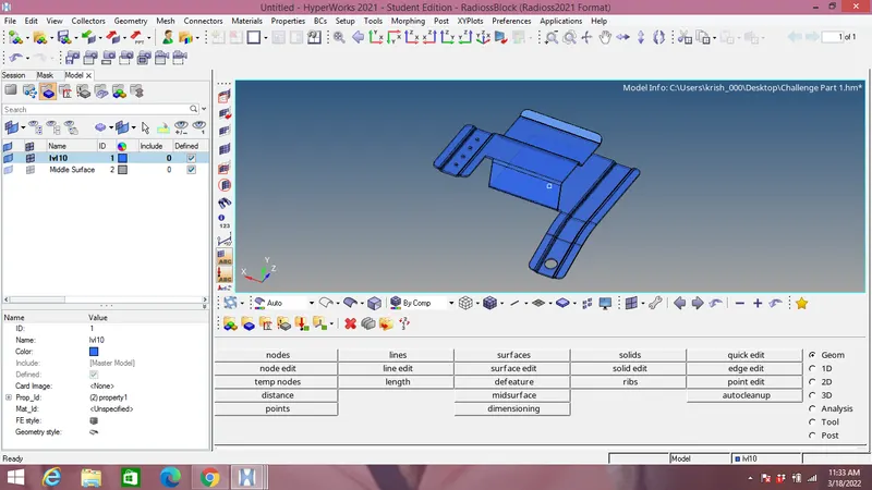
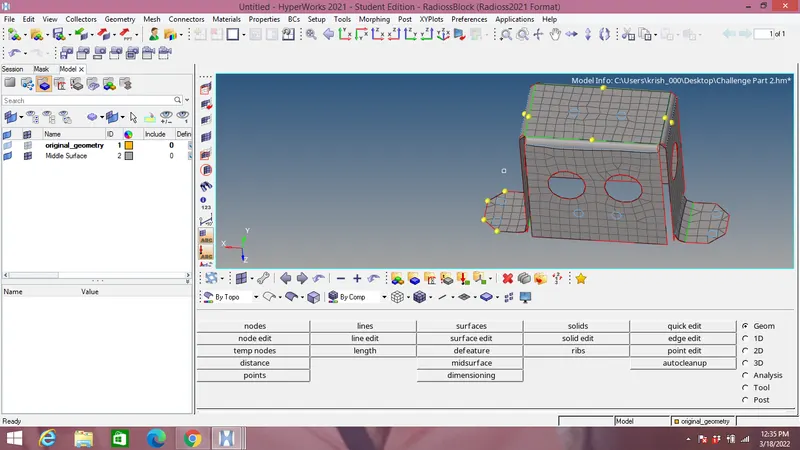
- Import it into Hypermesh Models with Radioss format as shown in the figure below.
Part 2:
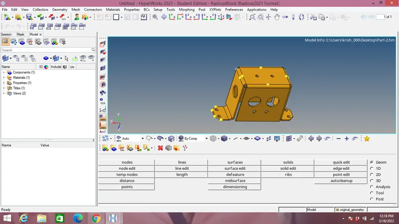
Same steps as part 1 is followed & model is imported as shown:
Part 3:
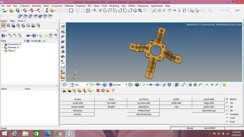
Same steps as part 1 is followed & model is imported as shown:
- Geometry cleanup of part 1:
Since Topo view contains surface irregularities in the model imported it should be cleared before obtaining the midsurface of the model as shown in the figure below:
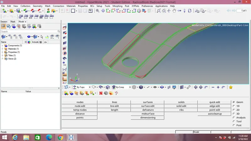
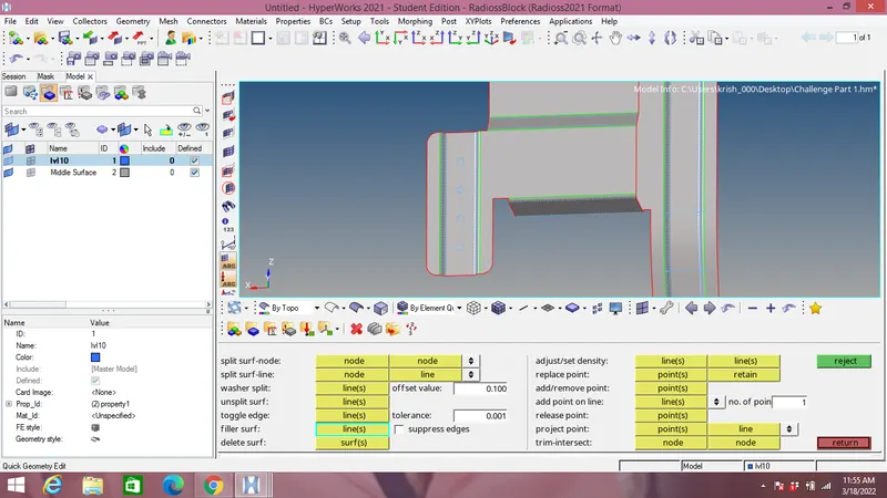
For missing surface the filler surface option under quick edit in Geometry panel is used.
For disconnected edges Toggle option is used which is again in the quick edit tab.
- Geometry cleanup of part 2:
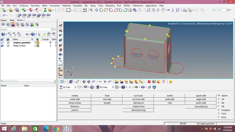
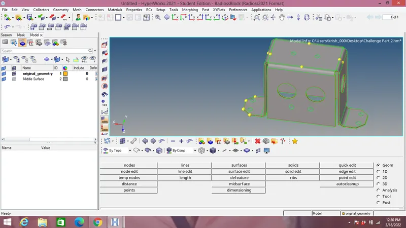
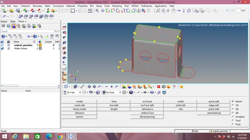
Since Topo view contains surface irregularities in the model imported it should be cleared before obtaining the midsurface of the model as shown in the figure below and 2 points are intersected as shown in the images: 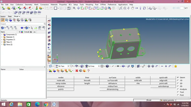
- Geometry cleanup of part 3:
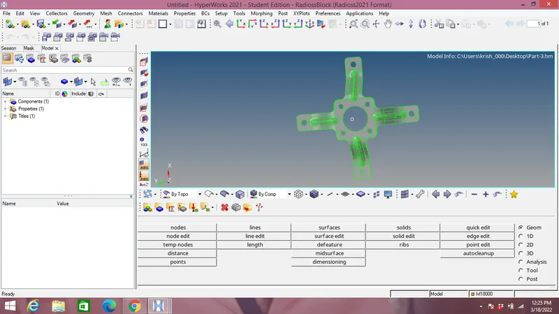
Since Topo view contains surface irregularities in the model imported it should be cleared before obtaining the midsurface of the model as shown in the figure below:
- Extraction of midsurface:
Part 1:
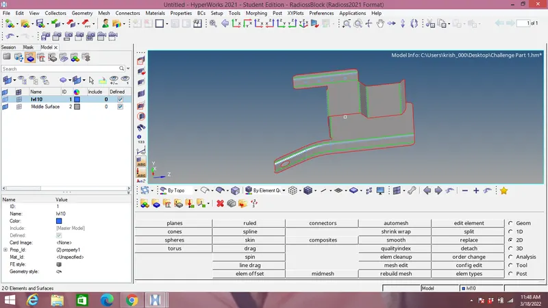
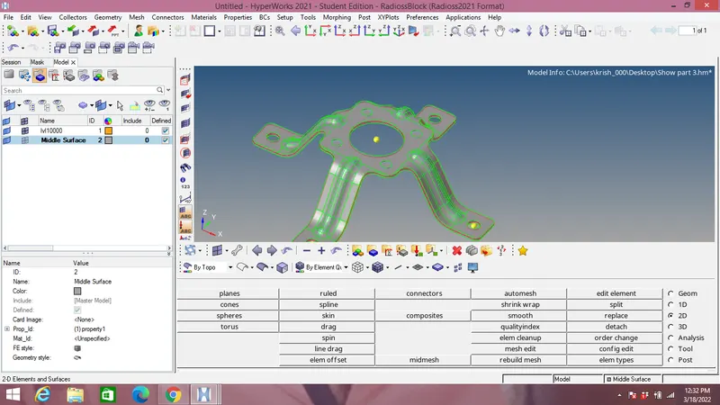
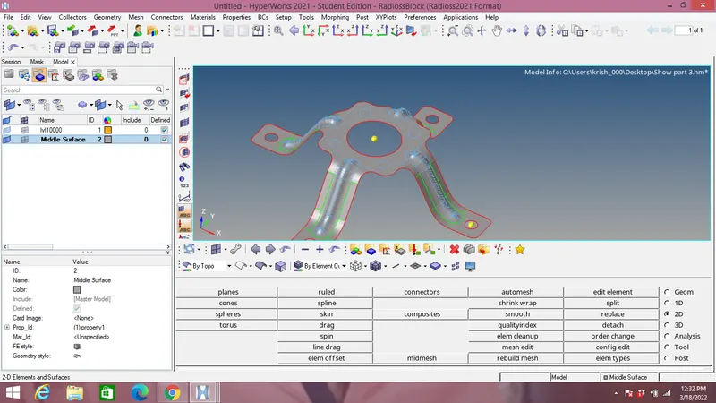
With the help of midsurface option in geometry panel & surface selection, the midsurface is extracted with offset+planes+sweeps. The midsurface extracted is shown in the image below:
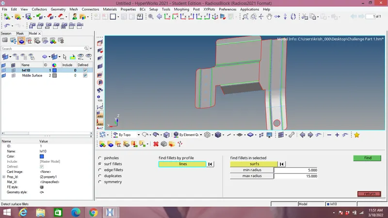
Next step is to find the fillets that will lead to minimum element size error using defeature option & defeature them as shown in the image below:
Next step is to fill the holes which are less than 5mm diameter, for that holes radius are measured using distance option in geometry panel and filler surface are used once their radius is found smaller than 5 mm as shown in the image below for the midsurface:
Part 2:
With the help of midsurface option in geometry panel & surface selection, the midsurface is extracted with offset+planes+sweeps. The midsurface extracted is shown in the image below:
Part 3:
With the help of midsurface option in geometry panel & surface selection, the midsurface is extracted with offset+planes+sweeps. The midsurface extracted is shown in the image below:
- Generating mesh:
For all part 1,2 & 3 this steps is same:
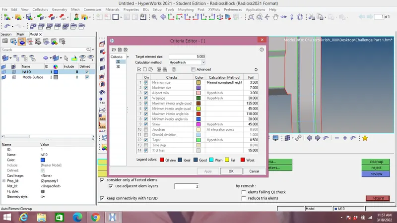
Before genearting mesh the edit criteria is selected in element cleanup in 2D mesh panel with target length as 5 mm,minimum element size as 3.5mm & maximum element size as 7 mm as per question above.
Part 1:
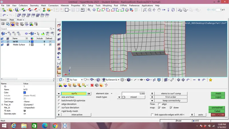
Meshing is doen with automesh in 2D mesh tab with element size as 5mm and type as mixed and meshing is doen surfacewise from small surface.
Part 2:
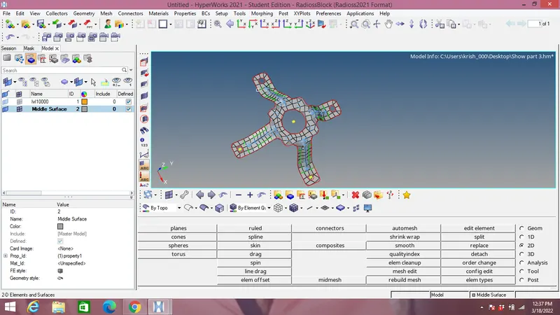
Meshing is doen with automesh in 2D mesh tab with element size as 5mm and type as mixed and meshing is doen surfacewise from small surface.
Part 3:
Meshing is doen with automesh in 2D mesh tab with element size as 5mm and type as mixed and meshing is doen surfacewise from small surface.
- Quality check:
Part1:
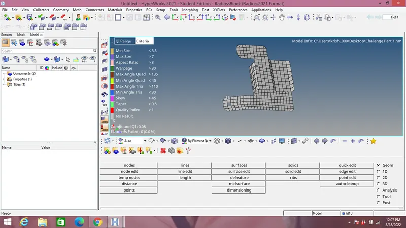
With quality index tool in 2D panel the elements violating the criteria is shown as yellow & red. The elements marked yellow & red are shown corrected using cleanup tool in 2D using smooth,element optimize & place node option.If elements are failing again then they are remeshed again to obtain the desired quality.
Part2:
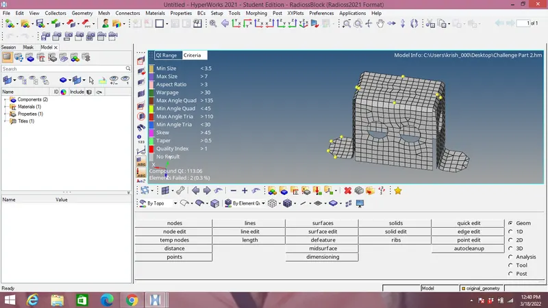
With quality index tool in 2D panel the elements violating the criteria is shown as yellow & red. The elements marked yellow & red are shown corrected using cleanup tool in 2D using smooth,element optimize & place node option.If elements are failing again then they are remeshed again to obtain the desired quality.
Part3:
With quality index tool in 2D panel the elements violating the criteria is shown as yellow & red. The elements marked yellow & red are shown corrected using cleanup tool in 2D using smooth,element optimize & place node option.If elements are failing again then they are remeshed again to obtain the desired quality.
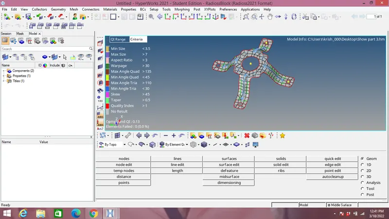
Next step is to check the free edges as shown in the image below:
Part 1:
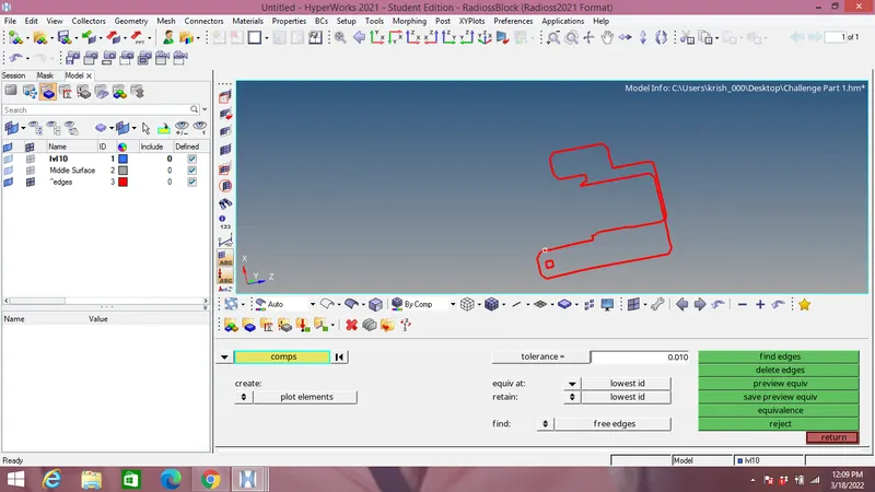
Part 2:
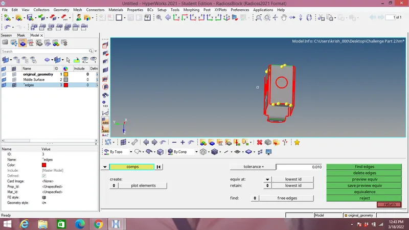
Part 3:
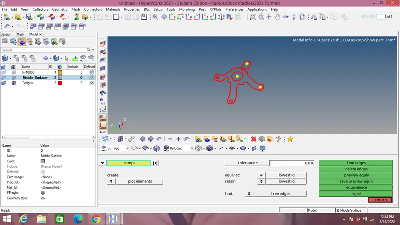
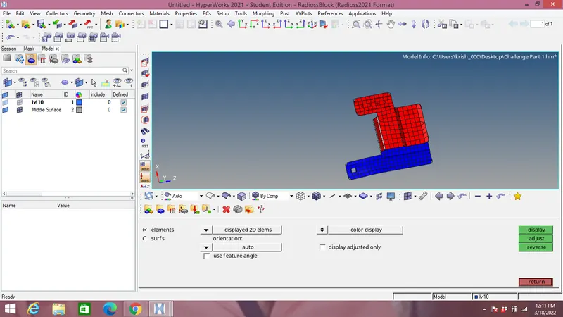
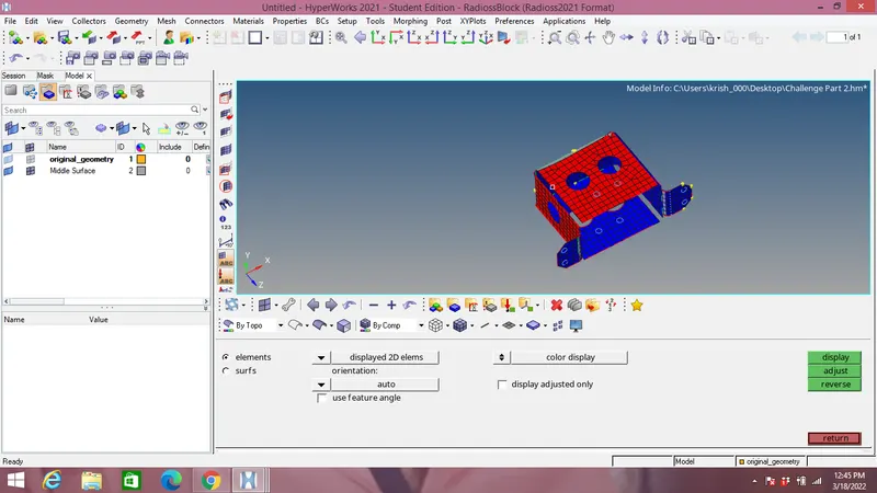
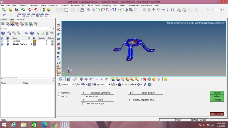
Next step is we check for the normals in Tool panel as shown in the image below:
Part 1:
Part 2:
Part 3:
- Assigning thickness:
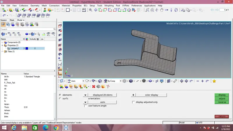
Part 1:
The thickness is assigned by creating the property under properties option and thickness of 0.91 mm is assigned to part1 as shown in the image below:
Part 2:
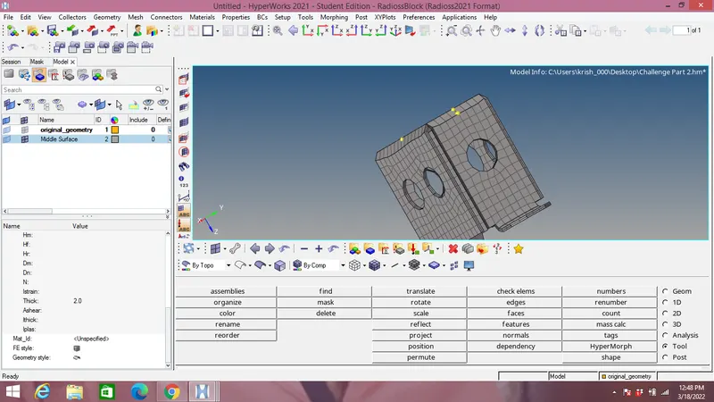
The thickness is assigned by creating the property under properties option and thickness of 2mm is assigned to part1 as shown in the image below:
Part 2:
The thickness is assigned by creating the property under properties option and thickness of 1.8 mm is assigned to part1 as shown in the image below: 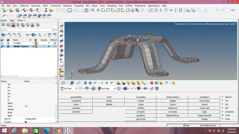
Conclusion:
- Extract the midsurface and performed the geometry cleanup as shown.
- Generate a 2D mesh on the given components.
- Finally assign the thickness as shown.