Assignment 3-2D Element Formulation Challenge
Comparison of results with base simulation and improved shell element properties:
Aim: Comparison of results with base simulation and improved shell element properties.
Steps followed:
- Import the given .rad file in hypermesh as shown in the image below:
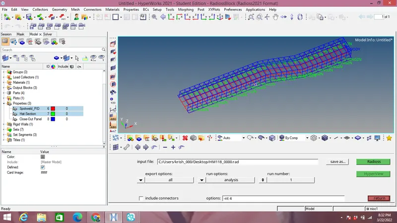
Case 1:
- Now the run time is changed as per question to 55 ms by selecting model browser and within it Engine run file in Card panel as shown in the image below:
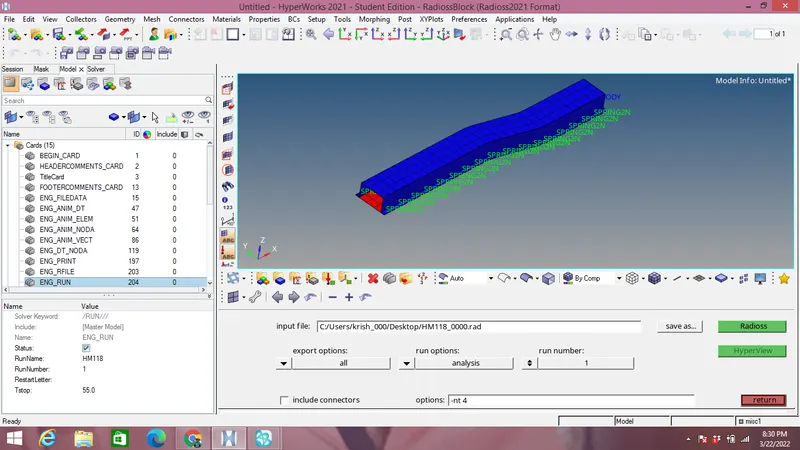
- Changing the animation step of simulation to 40 which is between 25 & 60 as per question.
- Frequency of run time is calculated which is equal to Run time/Animation step=55/40=1.375.
- The frequency calculated is inputed in the model browser within Card panel by selecting Engine ANIM_DT file as shown in the image below:
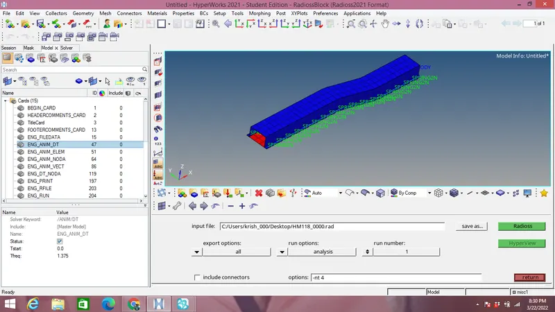
- Under Analysis panel we select the Radioss option with export-all,run options-analysis run number:1 & options as -nt 4 for number of threads.
- For saving the files we choose a suitable place and then we click on radioss button for generating the files as shown in the image above.
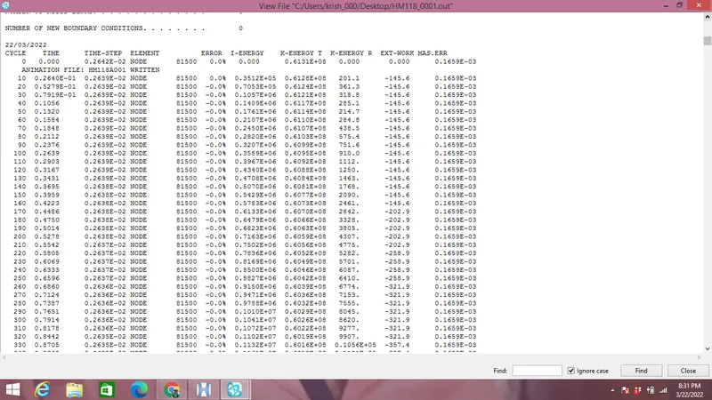
- After analysis the .OUT file is checked for energy & mass errors, which are under acceptable range as 0% to -10.3% and 0.1659E-003 respectively shown in the image below:
- Since errors are under acceptable range we now choose Hyperview section as shown in the image below:
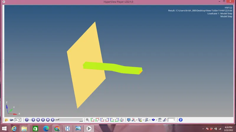
- Since energy & mass errors are acceptable we plot Rigid wall forces,internal energy,hourglass energy and Contact energy in Hypergraph 2D.
- Within Hypergraph 2D the file selected with name & shell formulation as T01.
- Specific energies are plotted on Internal energy vs time graph as shown in the image below:
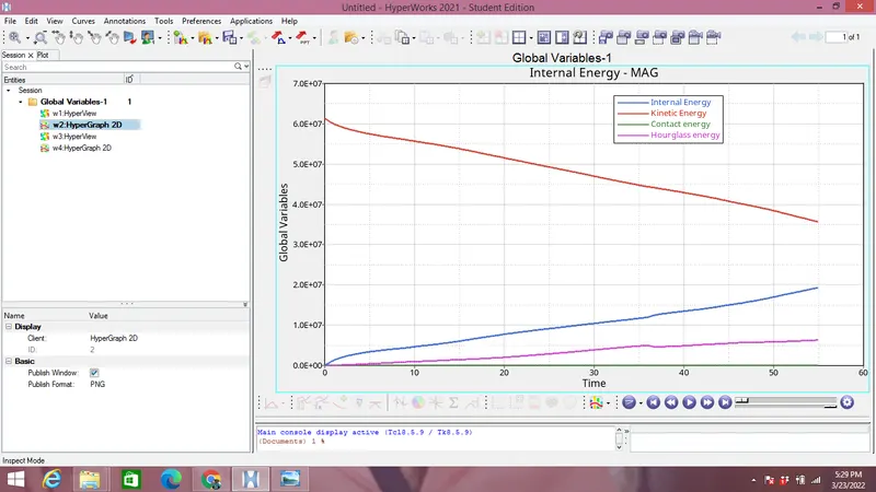
From the plot of Internal,Kinetic,Contact & Hourglass energies we observe that:
- Internal energy increases throughout the simulation because of deformation.
- Hourglass energy increases slightly throughout the simulation.
- Kinetic energy decreases as it is converted into deformation potential energy throughout the simulation.
- Contact energy remains zero throughout the simulation.
- A plot of rirgid wall forces containing normal,tangential & total resultant is also plotted as shown in the image below:
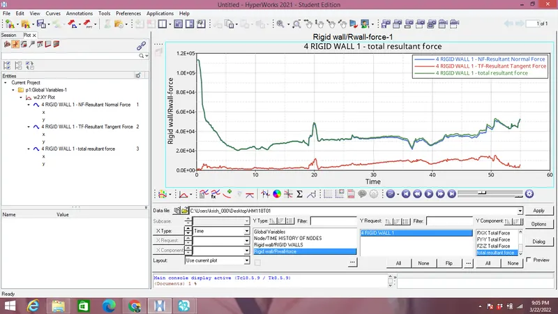
From the plot of rigid wall forces it can be observed that rigid wall forces are non-linear, which is again due to variation in the force exerted by the crush tube throughout the simulation.
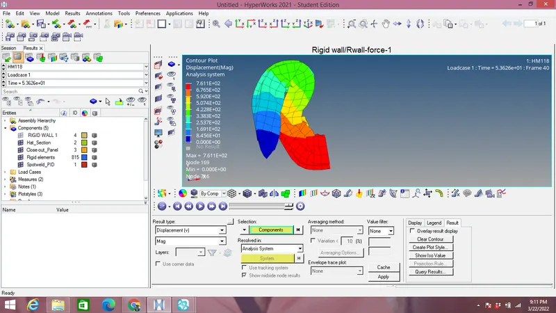
- Contour plot of displacement of tube with Hyperview format using contour is shown in the image below:
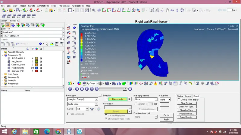
- Contour plot of Hourglass of tube with Hyperview format using contour is shown in the image below:
Case 2:
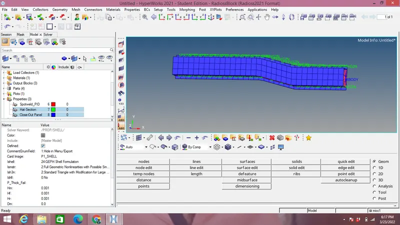
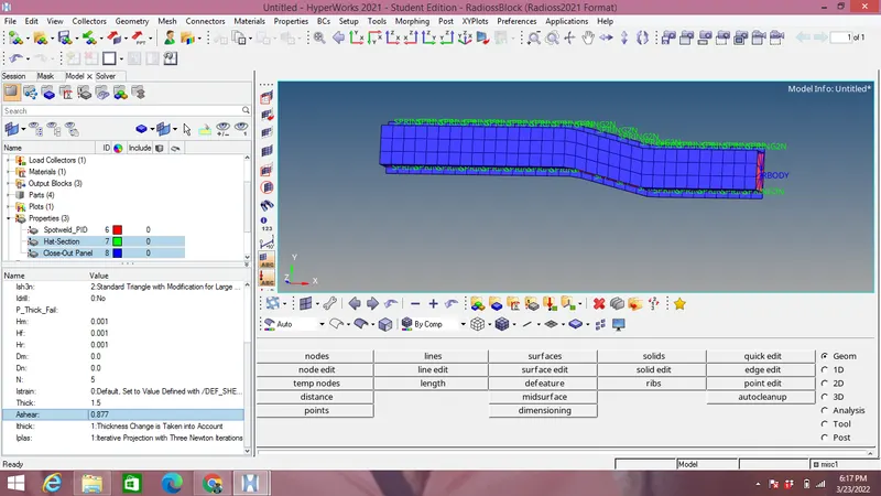
- Element formulation are changed from case 1 as:
| Parameters | Comments |
| Ishell =24 | QEPH 4 nodes shells are best combination of cost and accuracy |
| Ismstr=2 | Full geometric nonlinearities (default)with possible small strain formulation activation in RADIOSS Engine. |
| Ish3n=2 | Standard 3 noded shell (C0)with modification for large rotation(default) |
| N=5 | Number of integration points set to 5 for accuracy bending. |
| Ithick=1 | Thickness change is taken into account for accuracy. |
| Iplas=1 | Iterative plasticity for good accuracy. |
- Now the run time is changed as per question to 55 ms by selecting model browser and within it Engine run file in Card panel as shown in the image below:
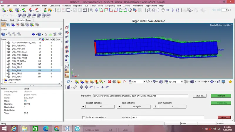
- Changing the animation step of simulation to 40 which is between 25 & 60 as per question.
- Frequency of run time is calculated which is equal to Run time/Animation step=55/40=1.375.
- The frequency calculated is inputed in the model browser within Card panel by selecting Engine ANIM_DT file as shown in the image below:
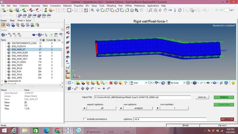
- Under Analysis panel we select the Radioss option with export-all,run options-analysis run number:1 & options as -nt 4 for number of threads.
- For saving the files we choose a suitable place and then we click on radioss button for generating the files as shown in the image above.
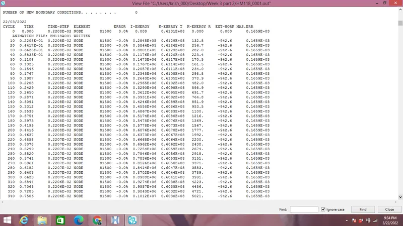
- After analysis the .OUT file is checked for energy & mass errors, which are under acceptable range as -0.0% to -0.0% and 0.1656E-003 respectively shown in the image below:
- Since errors are under acceptable range we now choose Hyperview section as shown in the image below:
- Since energy & mass errors are acceptable we plot Rigid wall forces,internal energy,hourglass energy and Contact energy in Hypergraph 2D.
- Within Hypergraph 2D the file selected with name & shell formulation as T01.
- Specific energies are plotted on Internal energy vs time graph as shown in the image below:
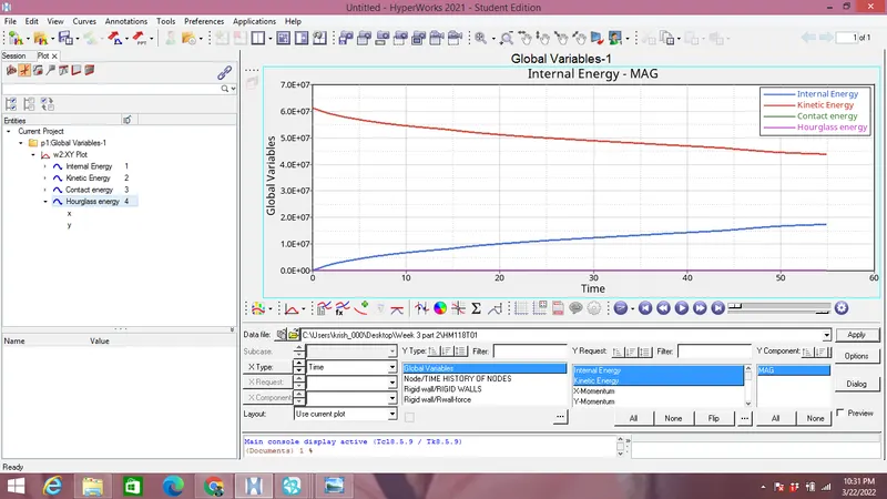
From the plot of Internal,Kinetic,Contact & Hourglass energies we observe that:
- Internal energy increases throughout the simulation because of deformation.
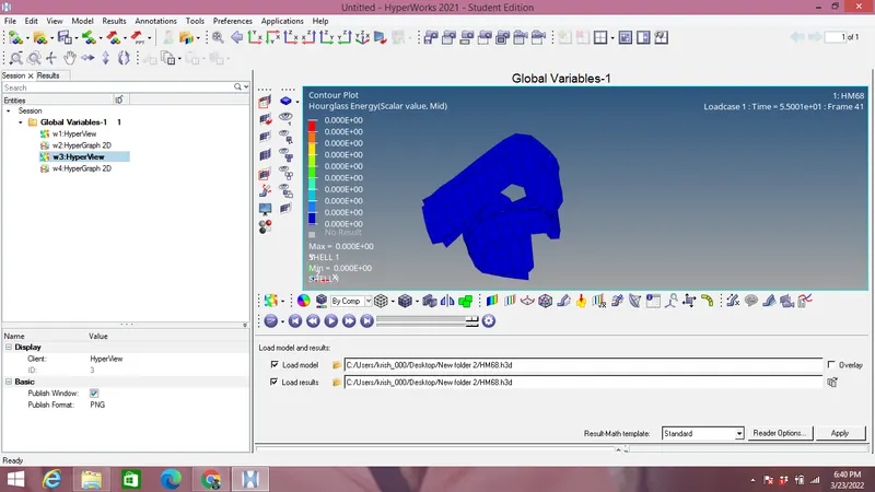
- Hourglass energy remains zero throughout the simulation
- Kinetic energy decreases as it is converted into deformation potential energy throughout the simulation.
- Contact energy remains zero throughout the simulation.
- A plot of rirgid wall forces containing normal,tangential & total resultant is also plotted as shown in the image below:
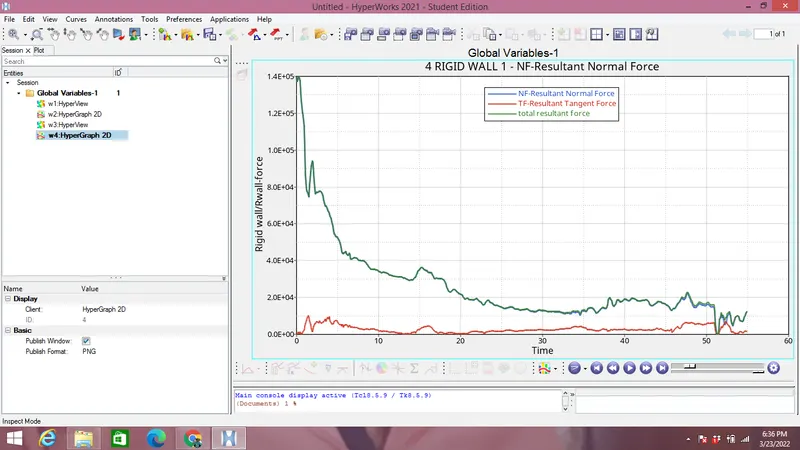
From the plot of rigid wall forces it can be observed that rigid wall forces are non-linear, which is again due to variation in the force exerted by the crush tube throughout the simulation.
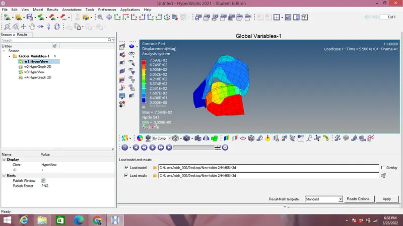
- Contour plot of displacement of tube with Hyperview format using contour is shown in the image below:
- Contour plot of Hourglass of tube with Hyperview format using contour is shown in the image below:
Comparision between case 1 &2:
It is observed from Internal energy & rigid wall image above for both the case 1& 2:
- When recomended properties are changed in case 2 Energy error remains zero at the entire simulation.
- Hourglass energy which was increasing in case 1 is chnaged to zero with recomended properties as observed from the Internal energy graph above.
- Contact energy remains zero in both the cases.
- Internal energy is gradually increasing in both the cases.
- Rigid wall normal forces increased in case 2 with recomended properties than case 1.
- Contour plot shows that there is slight decrease in displacement value in Case 2 compared to case 1.
Hourglass energy:
This type of energy in FEA is also known as zero energy node because no stress devloped on elements due to defomation of hourglass nodes.In a shell elements with reduced integration uses a single integration point,due to this the deformation results will be inaccurate.
In order to solve hourglass problem we have mesh refining with coarse mesh,elements with full integrations points are used though they are time consuming,providing a small arbitary stiffness to the element to avoid hourglass problem & Viscous damping.