Bird Strike - Project - 2
Bird Strike in Aero Engine:
Aim:
Simulation of bird strike in Aeroengine by using different mandatory cards in different files,parts,sections with proper numberinga etc.
Steps followed:
All units taken in Kg mm ms depending on conversion factor of Aluminium material provided in the question.
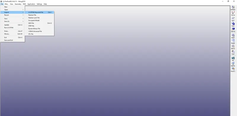
- Download the model provided above in .k format and open it using Import option under File of LS Prepost window.The model contains 4 parts which are casing,baldes,hub & bird:
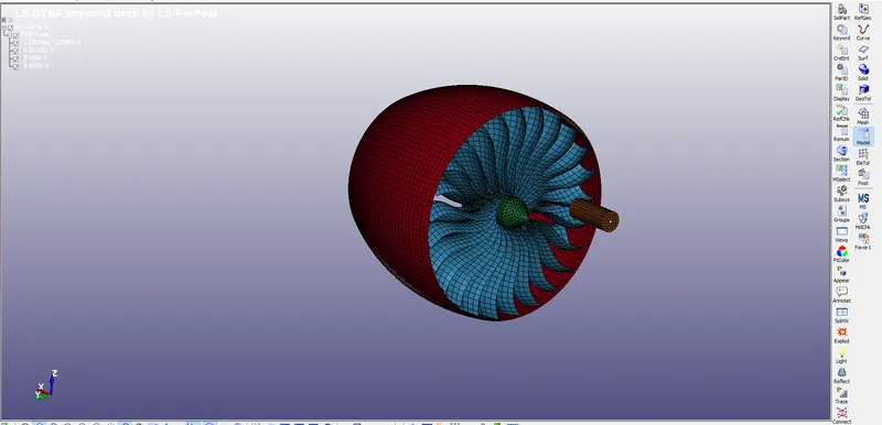
- Now delete the three parts and keep one part and save this file at appropriate location.
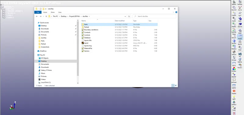
- Same is done for remaining three parts and they were saved under Part folder as shown in the image below:
Bird model:
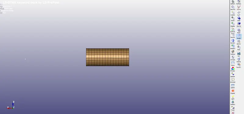
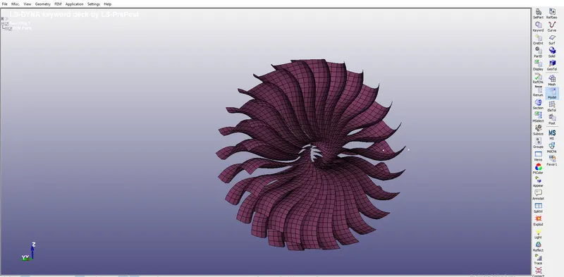
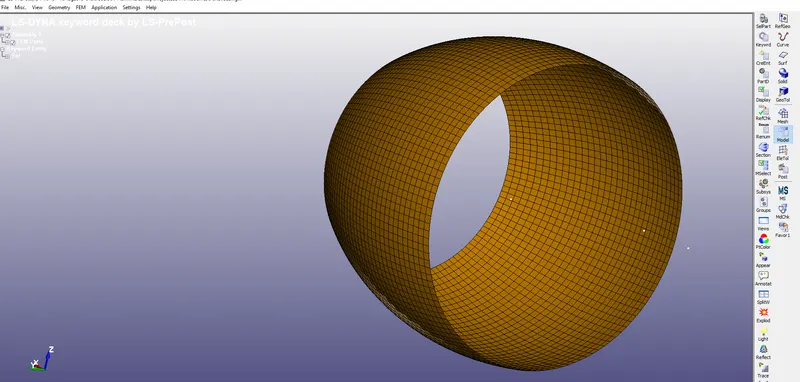
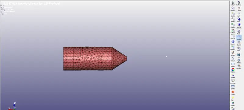
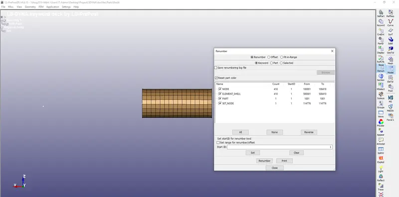
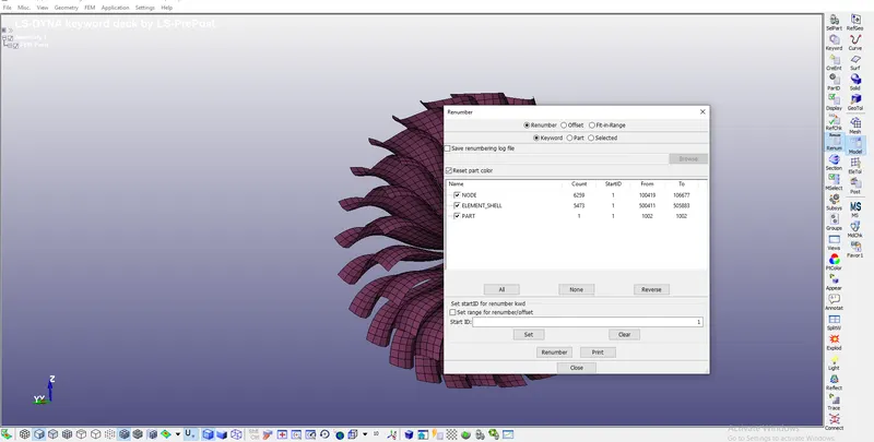
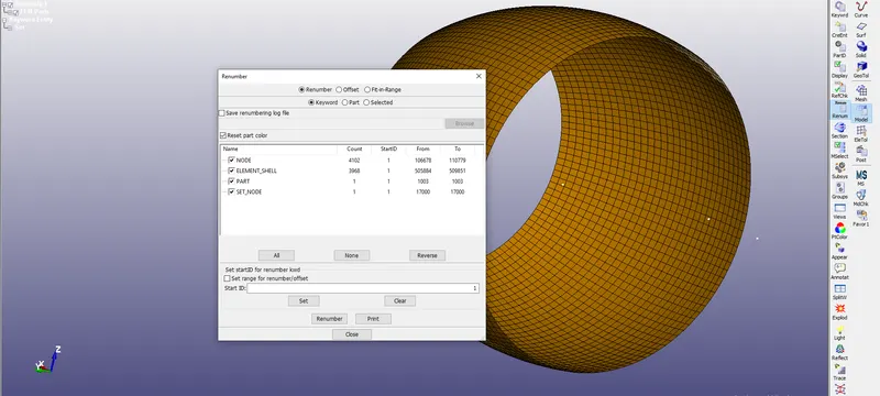
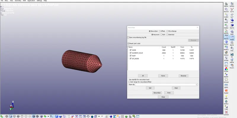
- Now go to Model at right toolbar and under renumbering input appropriate start ID for Nodes,elements & Parts:
|
Components |
Start ID |
End ID |
Bird
|
Node |
100001 |
100418 |
|
Element |
500001 |
500410 |
|
Part |
1001 |
1001 |
Blades
|
Node |
100419 |
106677 |
|
Element |
500411 |
505883 |
|
Part |
1002 |
1002 |
Casing
|
Node |
106678 |
110779 |
|
Element |
505884 |
509851 |
|
Part |
1003 |
1003 |
Hub
|
Node |
110780 |
114767 |
|
Element |
509852 |
530695 |
|
Part |
1004 |
1004 |
- Now open Material files downloaded,create a new MAT 001 Elastic card in LS Prepost with Young's modulus,Poission's ratio as Elastic material for Casing & Bird and Plastic material for blades & hub:
Mat_024_Peicewise_Linear_Plastic with Aluminum parameters having 1 card:
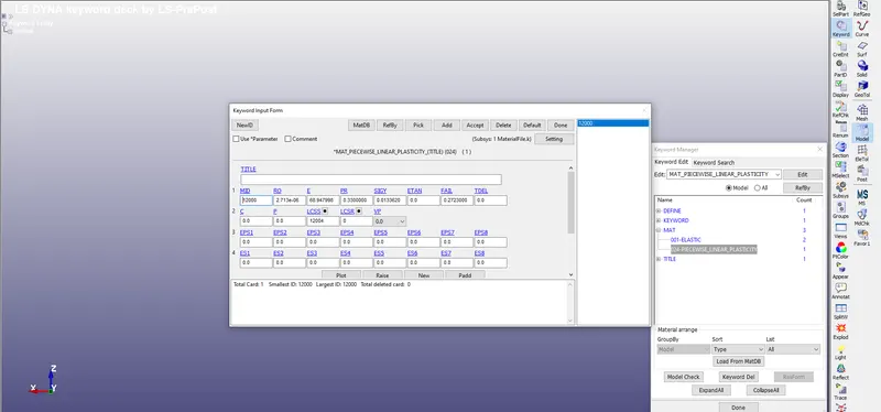
Mat_001_Elastic material with steel parameters having 2 cards:
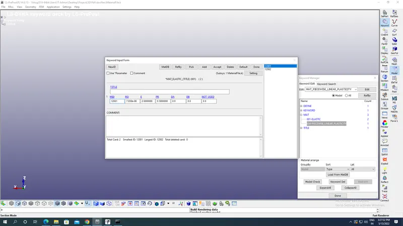
Material Cards are renumbered as parts with Model-Renumbering Key:
Materials:
|
3 materials |
Plastic Mat_ID 12000 |
Elastic Mat_ID 12001 12002 |
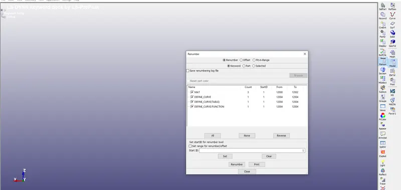
Now save the material file at appropriate location as doen for parts.
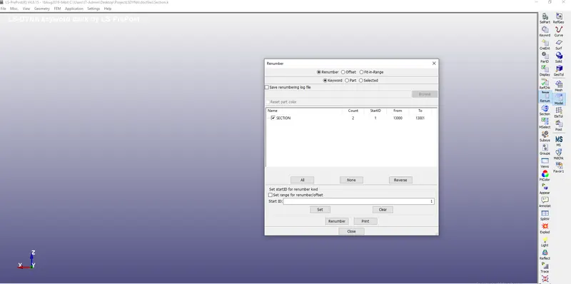
- Create two section cards of solid & shell under Model-Keyword-Section as shown in the new LS Prepost with appropriate renumbering as shown in the image below with 1mm thickness for shells:
Section:
| Start Ids |
SHELL-13000 |
SOLID:13001 |
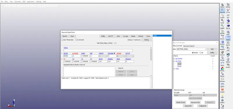
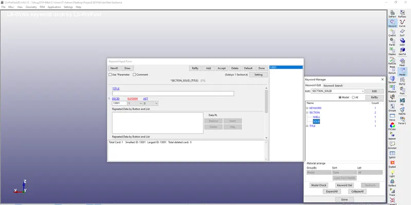
Save the section card & material card in different LS prepost files.
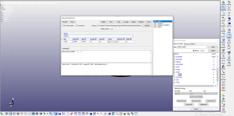
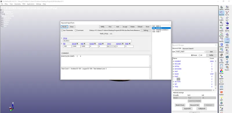
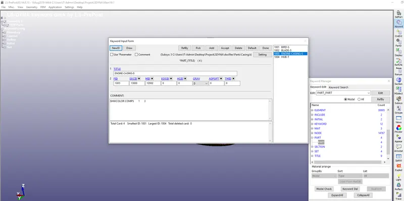
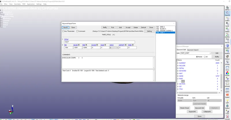
- Now assign the material & section ids to the parts created with renumbering option by opening Parts LS Prepost file created before and save the changed Parts as shown in the image below:
- Remember we are using Elastic material for Bird & Casing while Plastic for Blade & Hub.
- Solid section used for Hub while Shell used for Blades,casing & Bird.
Bird:
Blades:
Engine casing:
Hub:
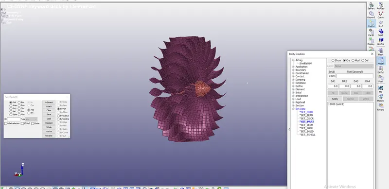
- Now create a part set for both Hub & Plate by opening new LS Prepost window as we want the Hub and Blades attached to it to rotate by taking both as one entity.
- This part creation is doen by Include Keyword under Model option as shown below and saving them and then later using Create Entity option under model by selecting SET Parts:
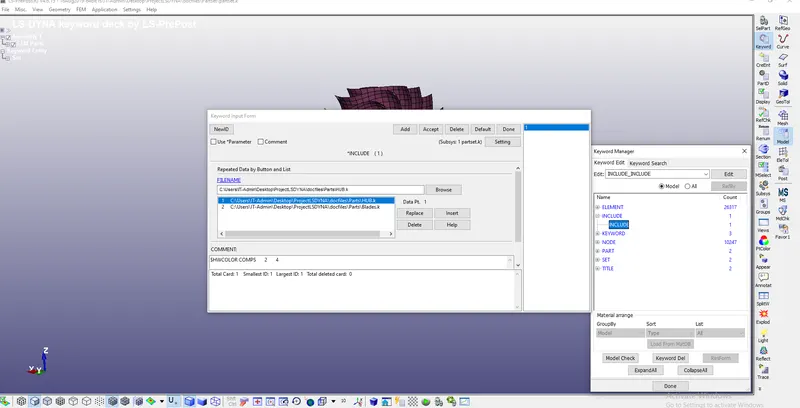
Set start ID given by renumbering option as shown below:
Set Parts:
|
Hub and Blades |
18000 |
18000 |
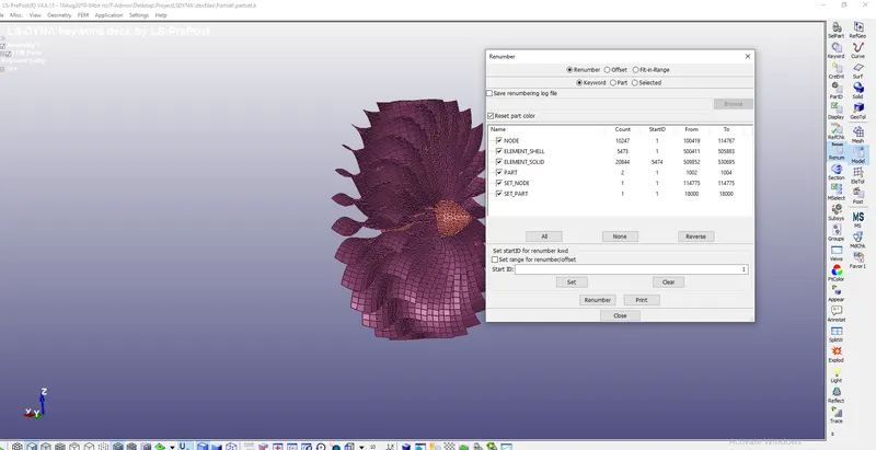
Now save the part set LS Prepost window and close that window.
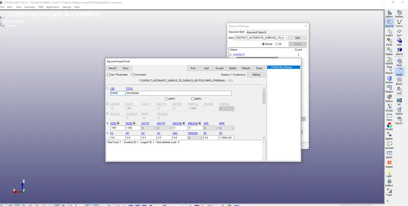
- Open the new LS prepost window and under Model-keyword-Contacts-Automatic Surface to Surface for BIRD & BLADE while Tied_Node_to_Surface for Hub & Blades as the blade & bird will be in contact in suface to surafce form so we use -Automatic Surface to Surface for Bird & Blade with Blade as Master & Bird as slave with Master & Slave set type as 3 for part Id selection as shown in the image below:
Now Tied node to surface defined for Hub & Blades again as we don't want any relative rotation between Hub & Blades with Master & Slave set type as 3 again for part id selection with Hub as master & blades as slave:
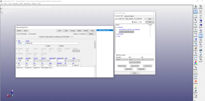
Proper Part ids are assigned to master & slaves as created for parts before.
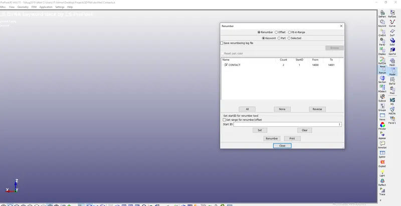
Contacts are renumbered as shown below:
Contact
|
Automatic Surface to Surface for Blades & Birds |
14000 |
14000 |
|
Tied Node to Surface between Blades and Casing |
14001 |
14001 |
Save the LS Contact file in appropriate location like doen for parts,sections,materials & part set.
- Now we open new LS Prepost window were we will create file for our Boundary canditions as shown in the image below with Keyword option under models.
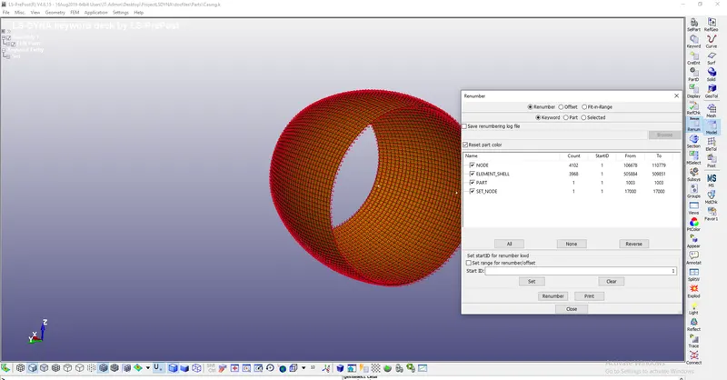
- First we will fix the casing by apply Single Point Constrained(Spc) with the help of Create Entity option-Boundary-SPC and by defining SPC SET under Casing part as shown below for selecting the spc set:
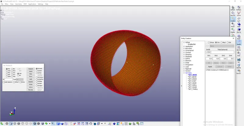
Set renumbering doen for Spc as shown below:
Set
|
Casing |
17000 |
17000 |
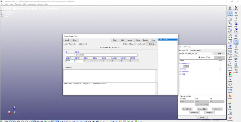
Open the Boundary canditions files again select the Spc under create entity option and assign the set as created in asing parts with same set ids as 17000:
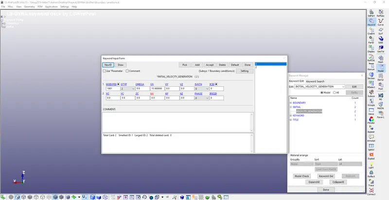
Apply Intial Velocity generation for applying Rotational and translational velocity under Model-keyword-Intial Velocity generation with appropriate Set type(STYP) for various types of parts,partset & node set.
For Translational velocity of Bird STYP as 2 and Bird part ID inserted as created by renumbering during Bird parts creation with proper velocity along X axis depending on the model imported as 15 mm/ms as shown below:
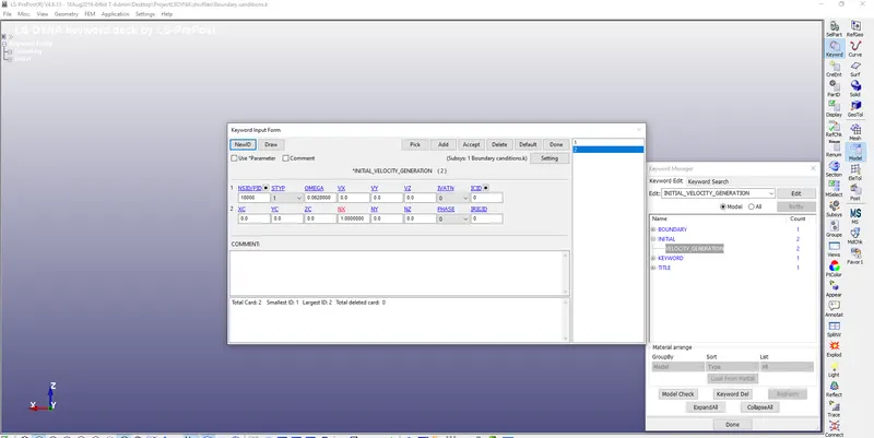
For Rotational Velocity we apply omega as 0.0628 rad/ms with STYP as 1 for part set of Hub & Blades with direction cosines as 1 for rotation about X axis as shown with part set ID selection:
Now save the Boundary candition LS prepost window at appropriate location.
- Now open new LS prepost and create Controls under Keyword Model option.
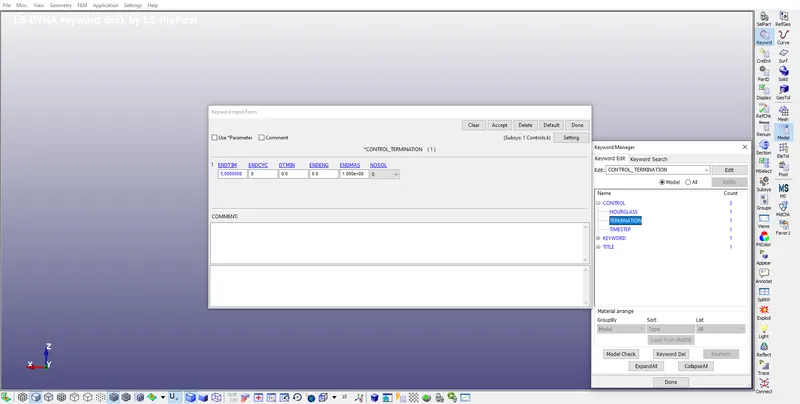
- Go to Controls and select the Termination time with END Time as 5 ms as shown below:
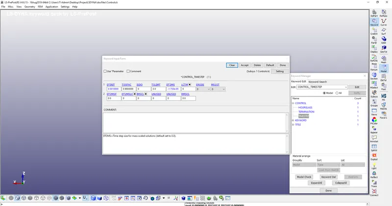
- Now select the Timestep under Control keyword for mass scaling with default DT2MS as -1.75E-05 as shown:
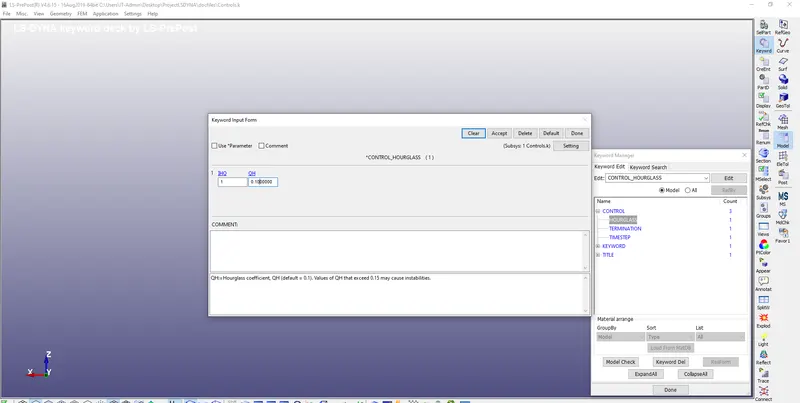
Now we will select Hourglass for our shell elements with Hourglass Viscosity(IHQ) as 1 for standard LS Dyna with Hourglass coefficient as 0.1:
Save the controls Ls Prepost window at appropriate location like done for other files prevoiusly.
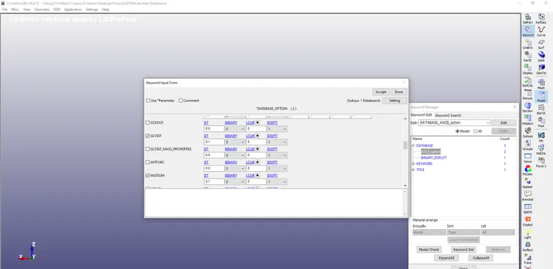
- Open new LS Prepost window and create Database under Keyword option and select the ASCII with GLSAT&MATSUM with DT as 0.1 which is time interval between outputs:
- Now define binary d3 plot with DT again as 0.1 ms as shown in the image below:
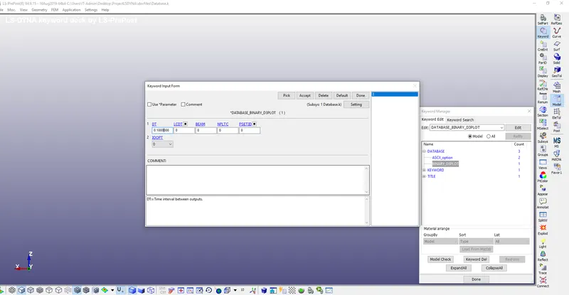
Save the Output requests-Database files at appropriate location like done for others.
- Now Open New LS Prepost window for our main file.
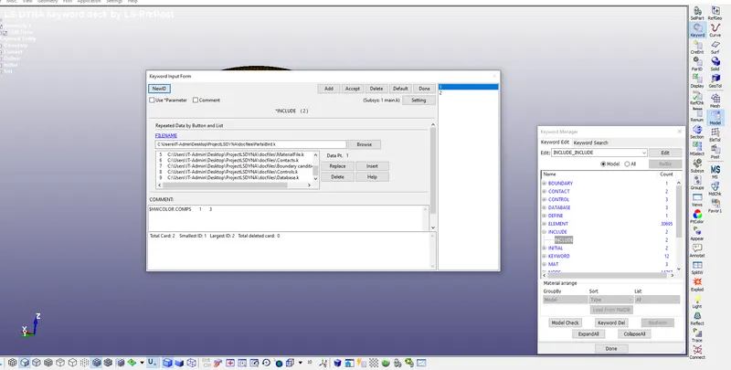
- Use Include Keyword under Model Option for including all the files which we created till now like parts,sections,materials,partset,contacts,boundary canditions,controls & database.
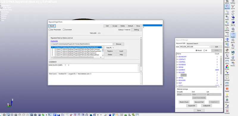
Rememeber instead of Blades & Hubs parts we are using the part set of them.
Now save the main file in appropriate location with new folder as Main 2 and try Running it. Termination time appears as 1 hr 47 mins with steps taken as dt=7.03E-05s with mass added percentage as 4.372E-06.
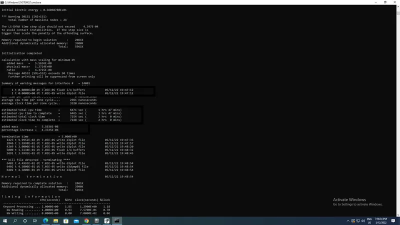
Now we will do mass scaling as we want to check whether our results are correct or not in Postprocessing so we increase DT2MS greater than dt obtained with provided DT2MS i.e. -7.030E-05 and termination time decreases as shown in the image below after running it:
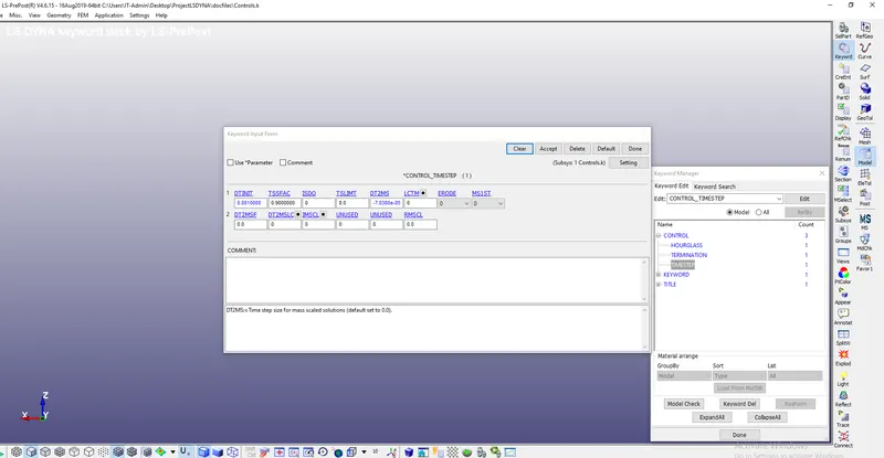
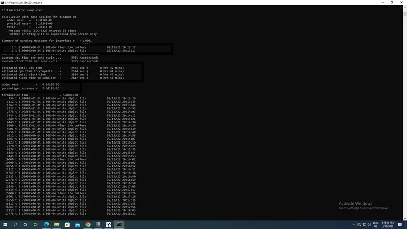
Termination time appears as 42 mins with steps taken as dt=1.80E-04ms with mass added percentage as 7.3411E-01.
On futher increasing DT2MS as -2.8E-04 i.e more than dt which occur previously :
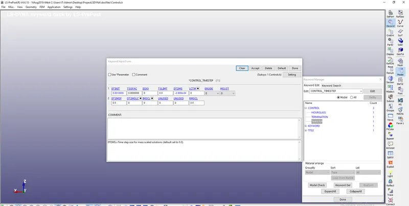
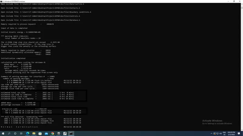
Termination time appears as 34 mins with steps taken as dt=2.52E-04ms with mass added percentage as 5.12 %.
On futher increasing DT2MS as -3.1E-04 i.e more than dt which occur previously :
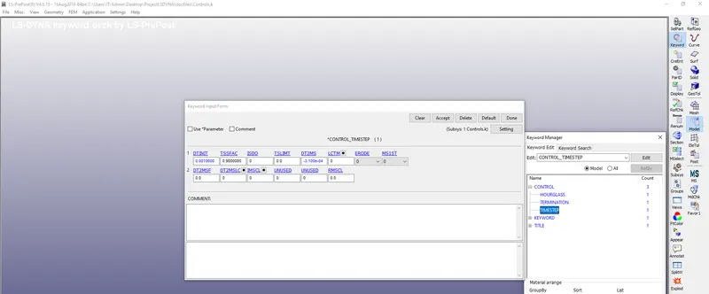
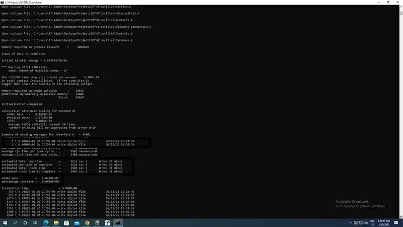
Termination time appears as 27 mins with steps taken as dt=2.79E-04ms with mass added percentage as 8 %.
Results:
Binary D3Plot of the simulation appears as shown below:
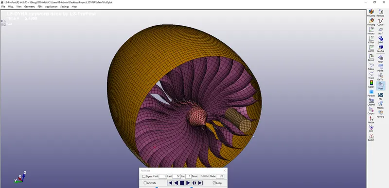
x-Stress:
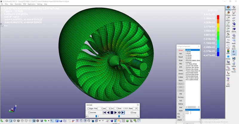
Maximum X Stress as 0.06452 GPa.
Von mises Stress:
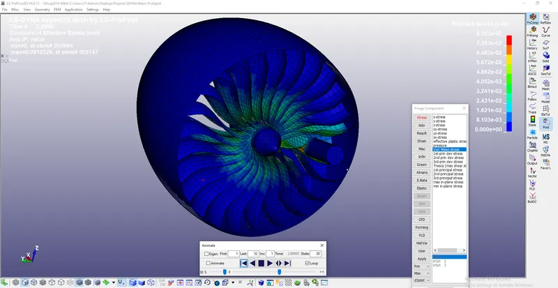
Maximum Von mises stress as 0.081 GPa.
Effective Plastic strain:
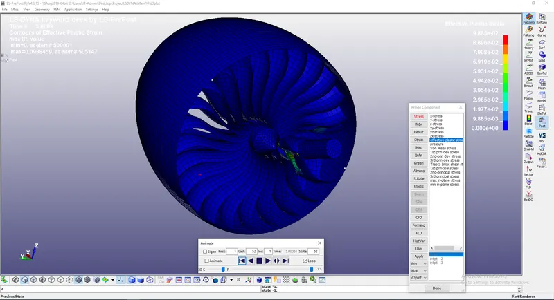
Maximum Effective Plastic strain is 0.098.
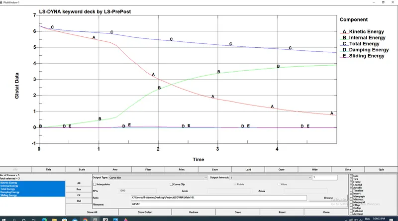
GLSAT Energy plot:
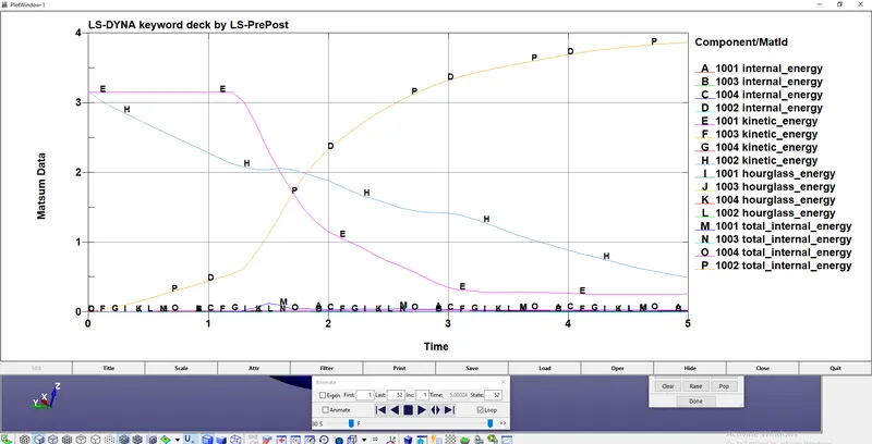
Matsum plots:
Conclusion:
.Diiferent parts,part set,section,materials,contacts,Boundary canditions,Control & Database were created in different LS Prepost window and saved with proper section,materials and ID assignments. They were included in main file and main file is runned and we decreased the Termination time of main file by using mass scaling in DT2MS in our saved Control files and final results were obtained using Trial and error method.
Rotational velocity of 0.0628 rad/ms is applied to the part set of hub & blade by taking direction cosines along X axis while translational velocity along X axis is applied on the birds and various stresses and strains were founded out during collissions of both.