Week 8 - Universal Joint
Transient structural analysis on Double Universal Joint wing spring:
Aim: Transient structural analysis on a double universal joint with a spring using three different materials of Structural Steel, Stainless Steel and Titanium alloy at the fixed joint of spring.
Steps followed:
1)Material Selection:
Case 1:
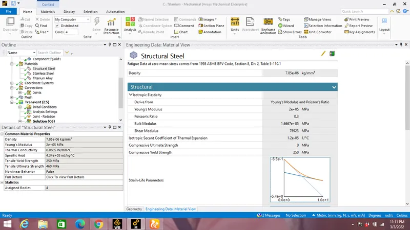
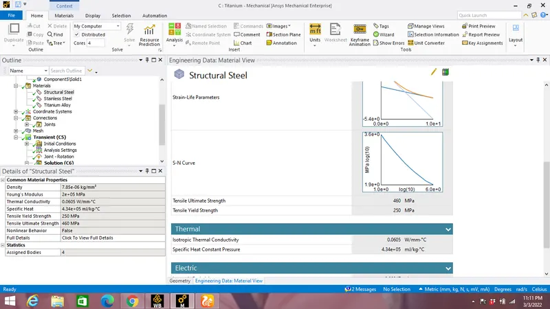
All the components are assigned Structural steel material with specifcations shown in the image below:
Case 2:
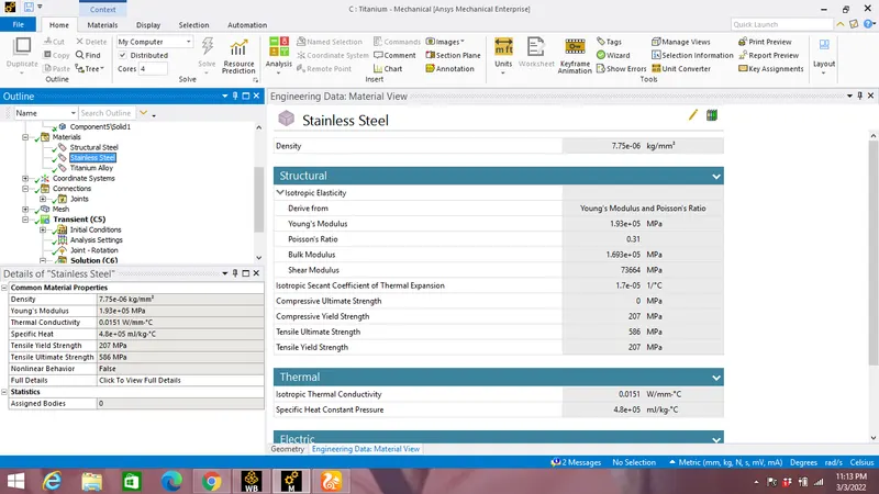
Stainless steel is selected for joint at the spring with material specification shown in the image below:
Case 3:
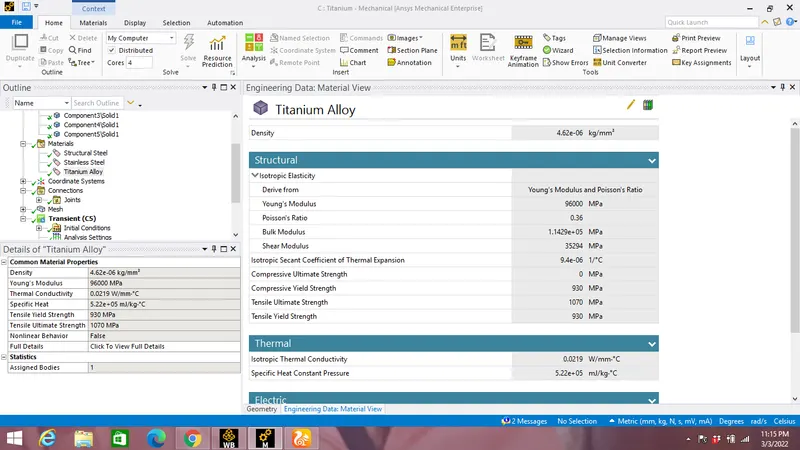
Titanium alloy is selected for joint at the spring with material specification shown in the image below:
2)Geometry:
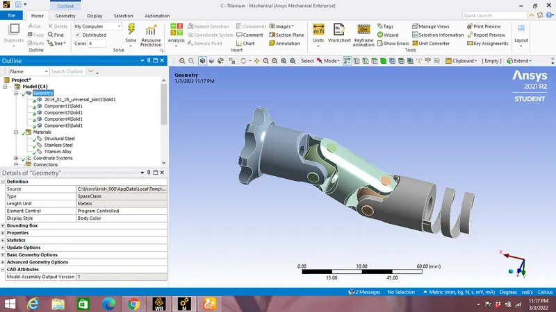
A CAD model of double universal joint with springs are imported in all 3 cases.
Material assingment to joint at spring:
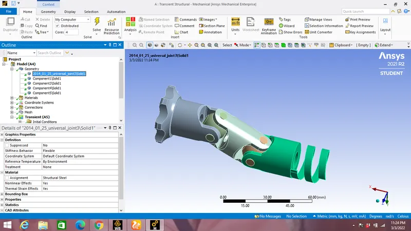
Case 1:
Structural Steel for joint at spring:
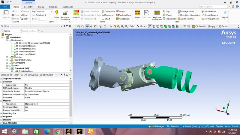
Case 2:
Stainless Steel for joint at spring:
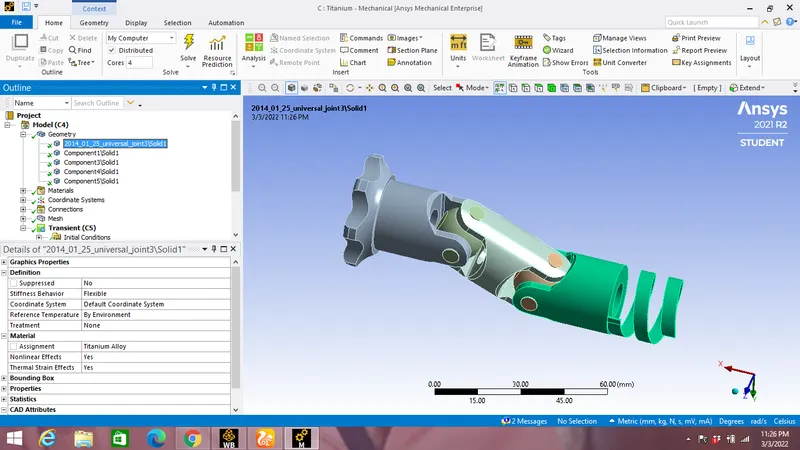
Case 3:
Titanium Alloy for joint at spring:
3)Joints:
a)Fixed Joint:
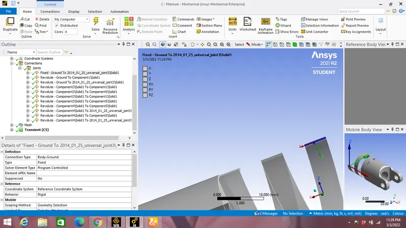
A fixed joint is applied at the spring with Connection type as Body-Ground by selecting its one of the face as shown in the image shown below:
b)Revolute Joint:
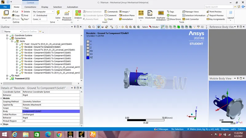
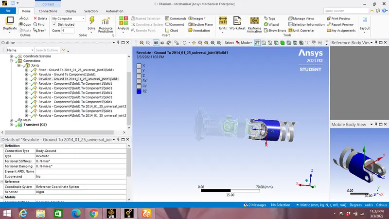
Two Revolute joint is applied at the Universal Joint with Connection type as Body-Ground by selecting its one of the face of each as shown in the image shown below:
c) Body-Body Connection type Revolute Joint:
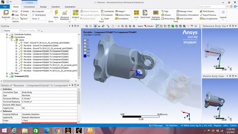
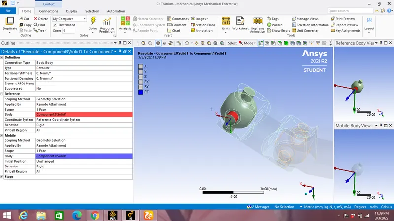
Eight Revolute joint is applied with Connection type as Body-Ground by selecting its one of the face of each Universal joint as mobile part & balls as reference as shown in the image shown below:
Mobile face of universal joint selected:
Reference face of balls selected:
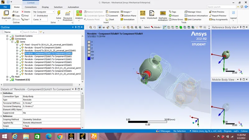
Mobile-Reference setting are shown for the 8 Body-Body revolute joints:
4)Meshing:
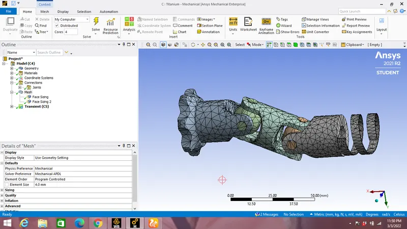
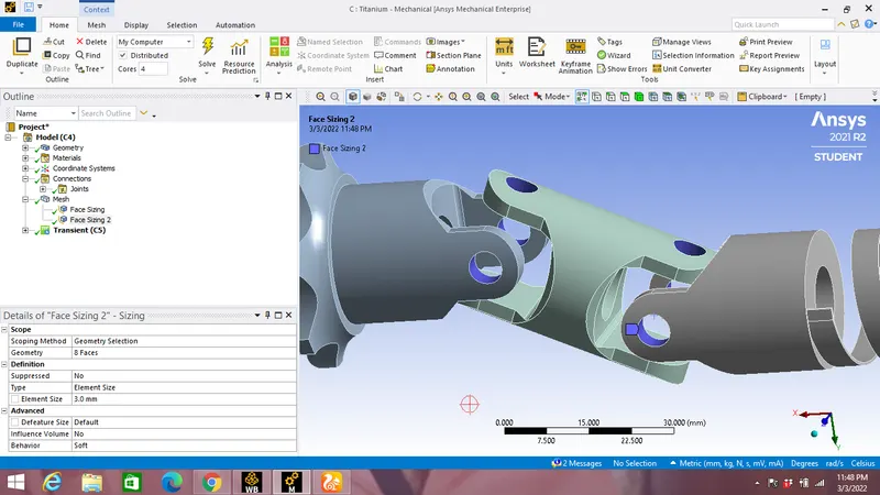
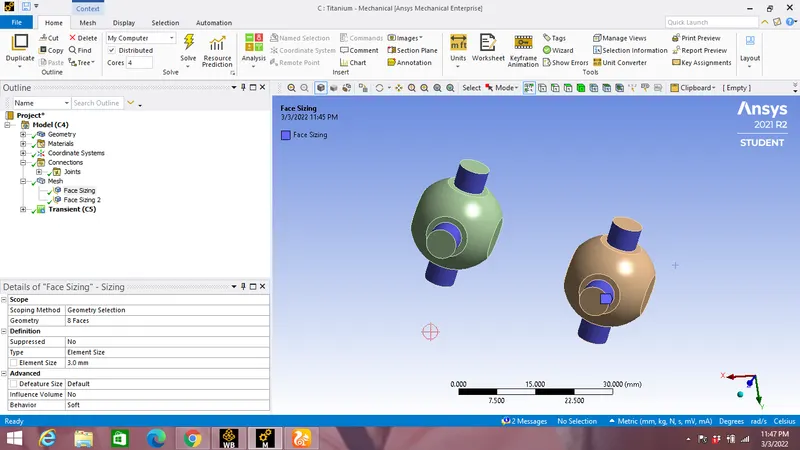
Meshing size of 4mm applied with face sizing of 3mm between the faces of balls & Universal joints in contact.
Mesh size of 4mm is shown in the image below:
Face sizing of 3mm between the faces of balls & Universal joints in contact:
5)Boundary canditions:
a)Analysis settings:
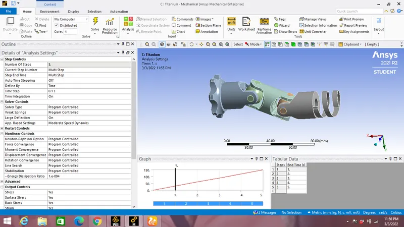
Analysis is doen by taking 5 as number of steps with Auto Time Stepping as off with Time Step of 0.1 and all Output Controls are switched On as shown in the image below:
b)Joint Rotation:
A joint load of rotation is applied by selecting the face of one of the Body-Ground type revolute joints not containing springs as shown below angle inputed in tabular format with rotation along Z axis.
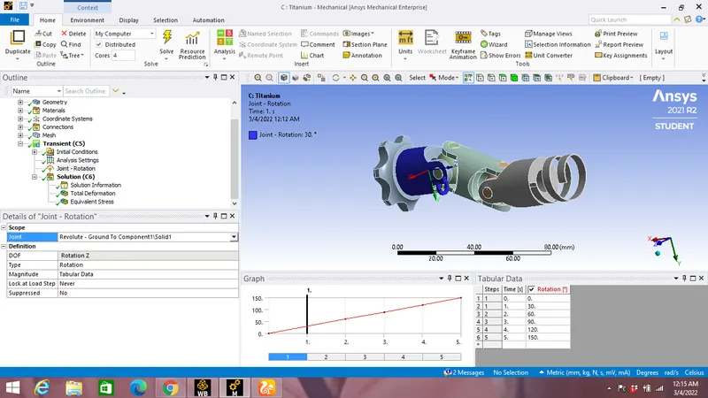
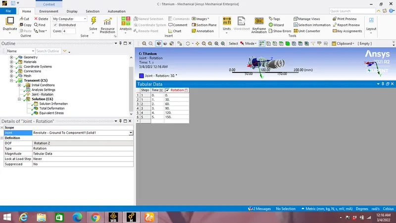
Tabular data of input angle:
Results:
Case 1: Structural steel for all components
Total Deformation:
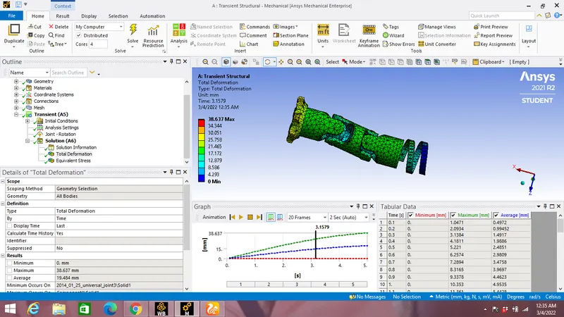
Total deformation vs Time graph:
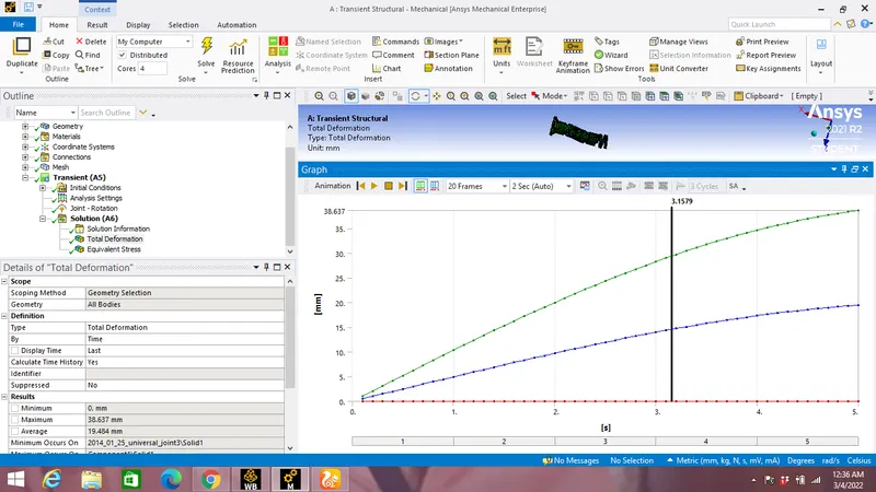
Maximum Total Deformation:38.637 mm
Equivalent Stress:
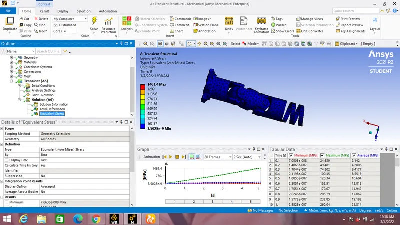
Equivalent Stress vs Time graph:
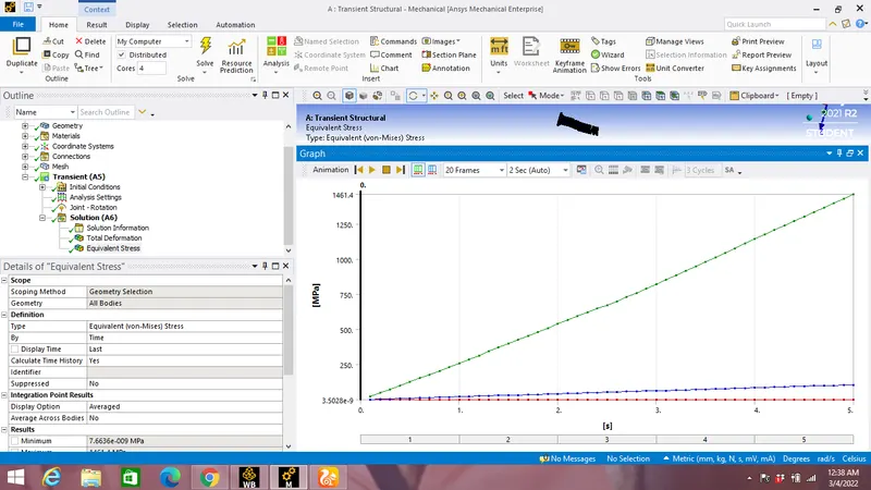
Maximum Equivalent Stress:1461.4 MPa
Case 2: Stainless steel for all spring joint
Total Deformation:
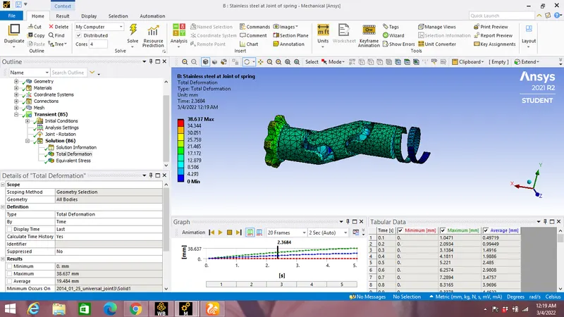
Total deformation vs Time graph:
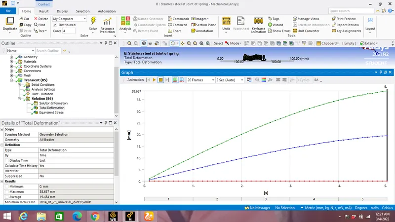
Maximum Total Deformation:38.637 mm
Equivalent Stress:
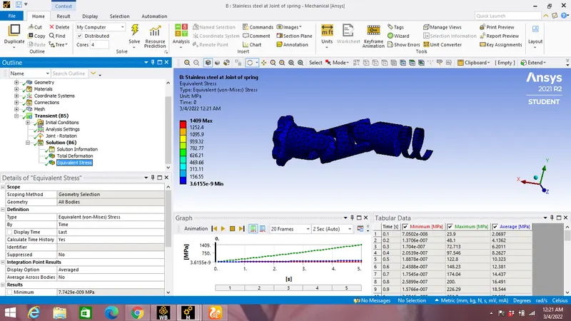
Equivalent Stress vs Time graph:
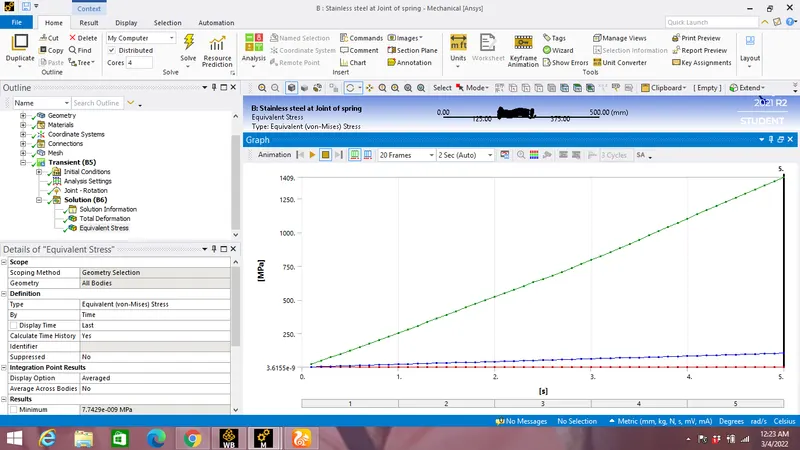
Maximum Equivalent Stress:1409 MPa.
Case 3: Titanium alloy for all spring joint
Total Deformation:
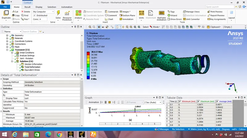
Total deformation vs Time graph:
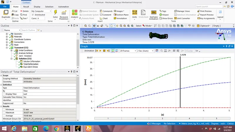
Maximum Total Deformation:38.637 mm
Equivalent Stress:
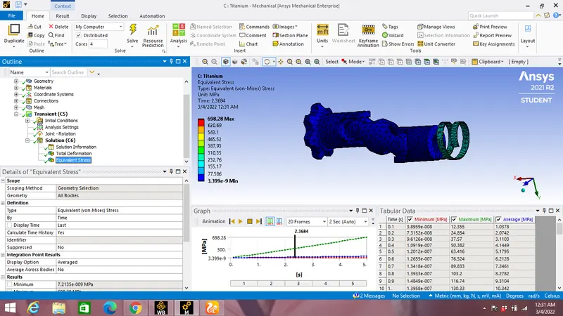
Equivalent Stress vs Time graph:
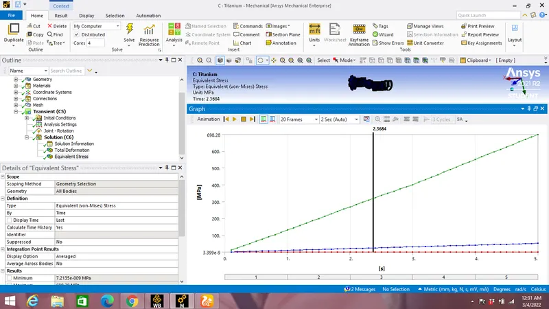
Maximum Equivalent Stress:698.28 MPa.
Comparision of Maximum Equivalent Stress & Maximum Total Deformation for case 1,2 & 3:
| Case | Maximum Equivalent Stress(MPa) | Maximum Total Deformation (mm) |
| 1 | 1461.4 | 38.637 |
| 2 | 1409 | 38.637 |
| 3 | 698.28 | 38.637 |
Conclusion:
- From the table above it can be clearly seen that highest maximum equivalent stress occurs in case 1 where all components are made up of Structural steel while lowest stress occurs for Titanium alloy spring component of Universal joint.This occurs due to high Yield & Ultimate strength of 930 MPa & 1070 MPa respectively for Titanium Alloy compared to Structural steel and Stainless steel.
- Total Deformation is same all three cases however which is 38.637 mm.