Project 2 - Crush analysis of aluminium Tube
Crush analysis of aluminium Tube:
Aim:Crush analysis of Aluminium tube with the rigid wall.
Procedure:
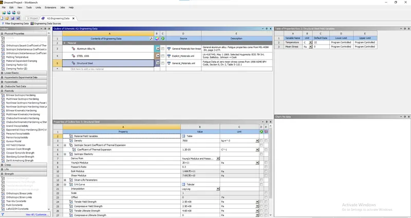
- Material selection of Structural Steel with material parmeters as shown in the image below:
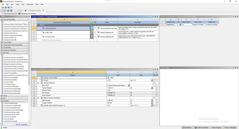
- Aluminium Alloy NL is selected from the list of General Non-linear materials for the tube to be crushed with materialm parameters as shown in the image below:
- Geometery:
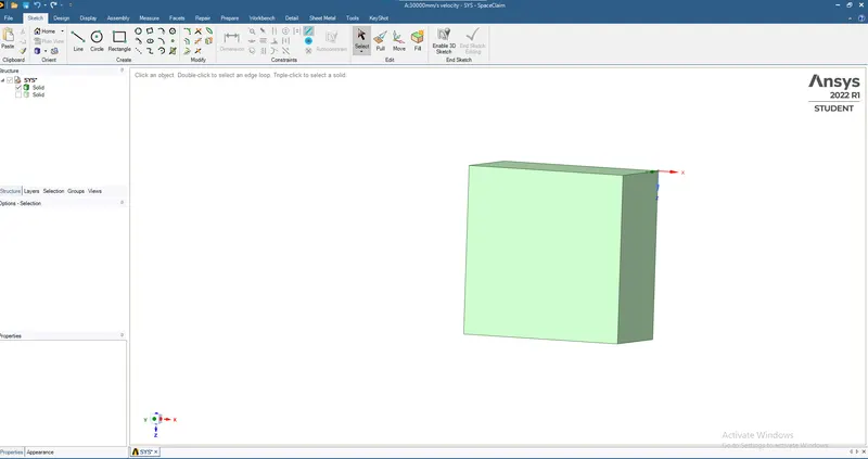
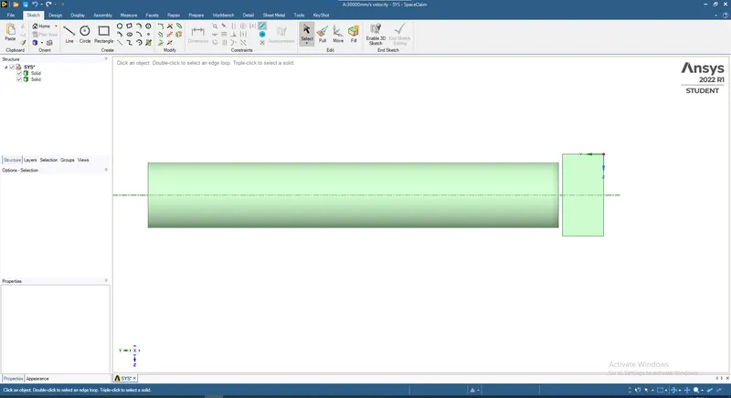
A square of 40x40 mm is drawn and extruded with 20 mm thickness as shown in the image below:
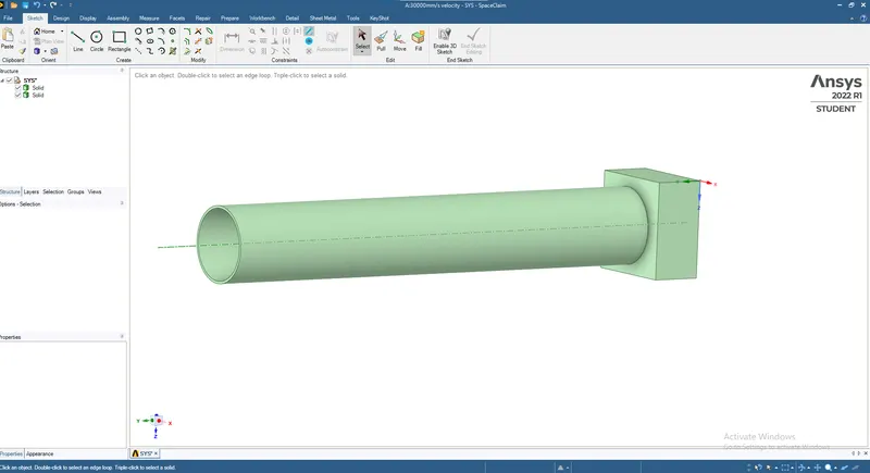
A circle with diameter of 30 mm is drawn and surrounding it another circle of 32 mm diameters is drawn so that thickness of 1 mm is maintained and finally extruded with 200 mm length and gap between wall & cylinder kept as 1 mm as shown in the image below:
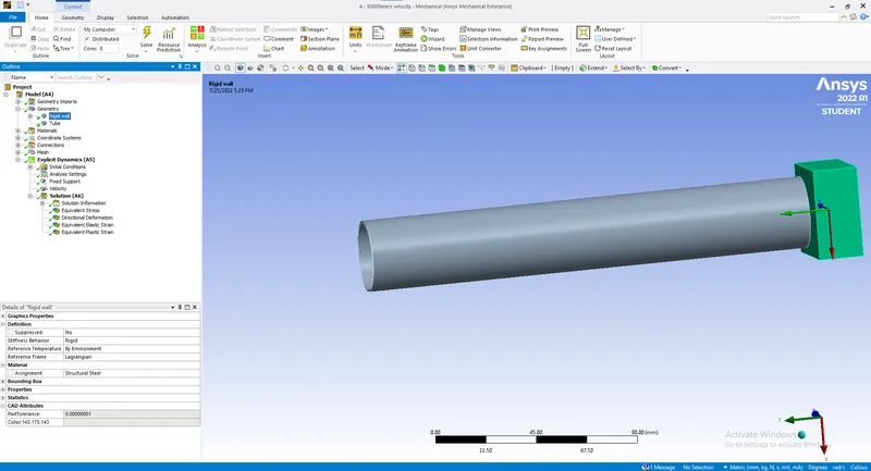
- Open the model after updating it and assign Structural steel to the rigid wall with stiffness behavoiur as rigid:
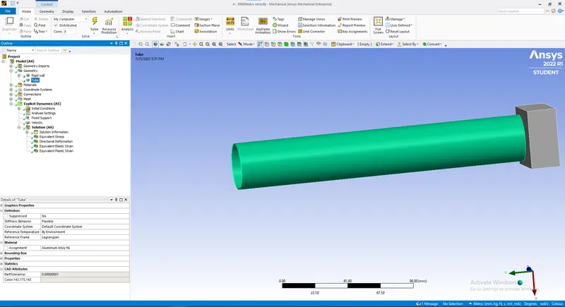
- Do the same for the tube as shown but stiffness behaviour as Flexible this time:
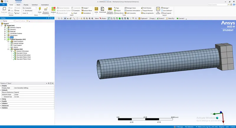
- Meshing:
Apply meshing of 5 mm to the tube as shown in the image below:
- Boundary canditions:
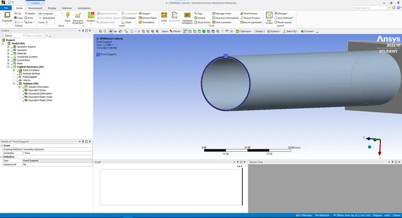
We have to apply fixed support at the other end of tube to be crushed as shown in the image below:
For velocity we have 4 different cases.
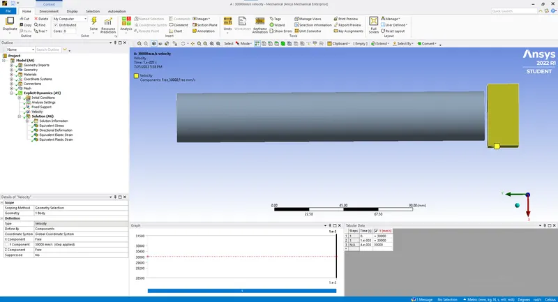
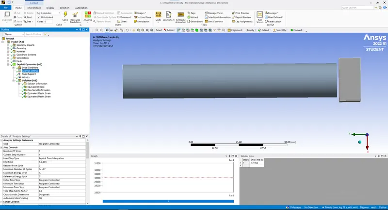
Case 1: Imposed Velocity of 30000 mm/s is applied to the rigid wall along Y axis as shown in the image below:
Case 2:
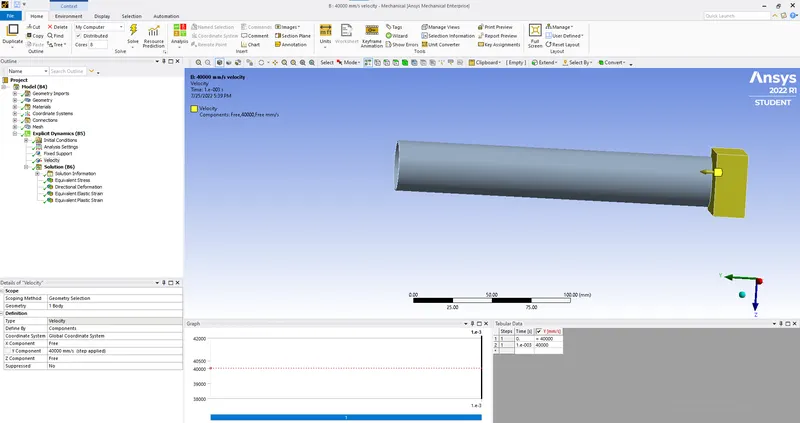
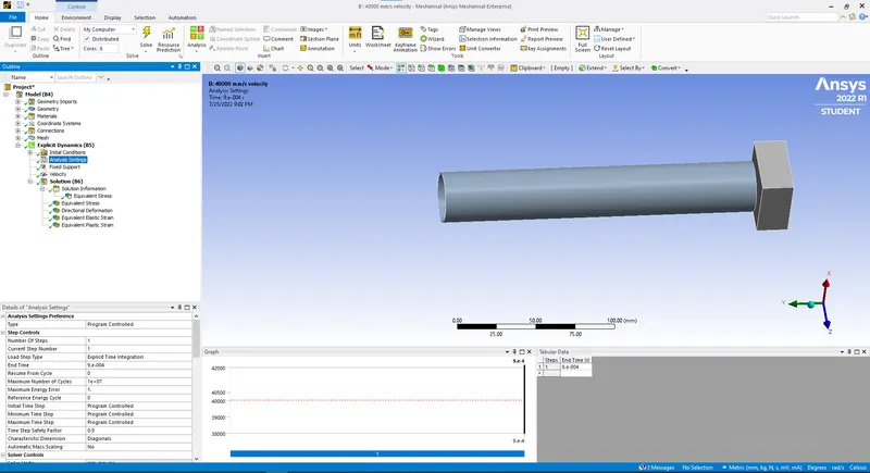
Velocity of 40000 mm/s is applied to the rigid wall
Case 3:
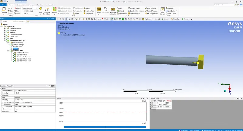
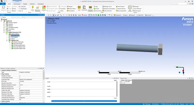
Velocity of 50000 mm/s is applied to the rigid wall:
Case 4:
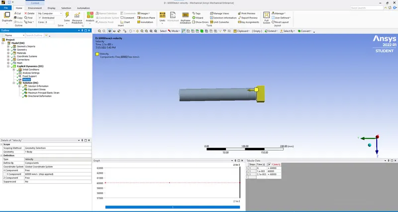
Velocity of 60000 mm/s is applied to the rigid wall:
- Analysis:
End time for case 1 is given as 1 E-03s with energy error as 1 as shown in the image below:
End time for case 2 is given as 9 E-04s with energy error as 1 as shown in the image below:
End time for case 3 is given as 1.9 E-03s with energy error as 1 as shown in the image below:
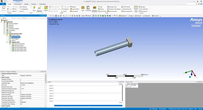
End time for case 4 is given as 2.1 E-03s with energy error as 1 as shown in the image below:
Results:
Case1:
Equivalent Stress:

Maximum equivalent stress:772.04MPa
Y-Deformation:
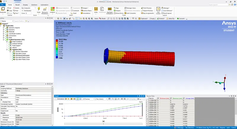
Maximum directional deformation:28.023mm
Case 2:
Equivalent Stress:
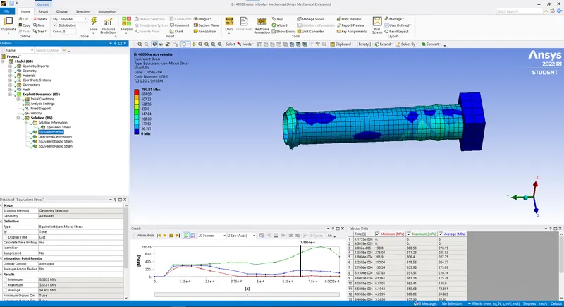
Maximum equivalent stress:780.04MPa
Y-Deformation:
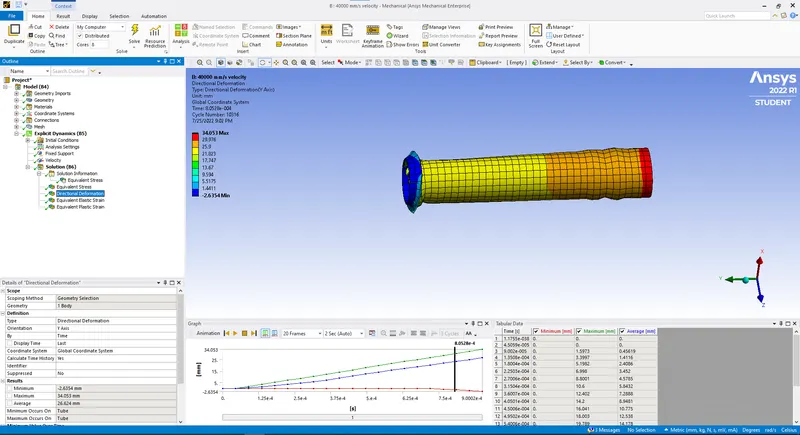
Maximum directional deformation:34.053mm
Case 3:
Equivalent Stress:
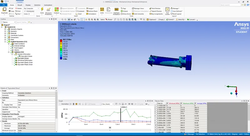
Maximum equivalent stress:801.35MPa
Y-Deformation:

Maximum directional deformation:105.62mm
Case 4:
Equivalent Stress:
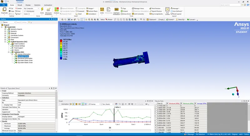
Maximum equivalent stress:1025.6MPa
Y-Deformation:
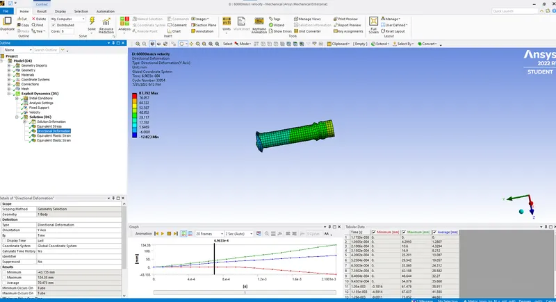
Maximum directional deformation:134.38mm
Conclusion:
The maximum equivalent stress is observed when rigid wall is having velocity of 60000 mm/s of 1025.6 MPa & maximum deformation is observed in that same case of 134.38 mm which is much higher than compared to other three cases with wall velocities of 30000,40000 & 50000 mm/s.