MESHING OF HOOD
MESHING OF COMPONENTS OF HOOD PANEL
OBJECTIVE: Aim of this project is to create meshing on the provided CAD data of the hood component while making sure that the elements of the mesh are within the given quality criteria.
REQUIREMENTS:
- Target Element Length = 5 Units
- Use ‘Mixed’ elements
- Save each component separately
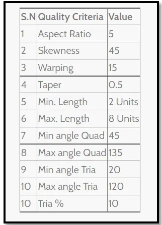
- Quality criteria:
THEORY:
2-D MESHING: We opt for 2D meshing whenever the thickness of the component is 5mm or less. Even if the hood panel is 3D, there will be not much difference between 2D meshing and 3D meshing as the thickness of the hood panel is usually 0.75mm. Creating a mesh with 2D elements will reduce the number of elements in the component and also the time required to solve the problem. Thus, whenever we have a part with a thickness less than 5mm, we should mesh it with 2D elements.
Thumb rule for handling tria elements in the model: As we are creating a mesh with mixed elements, it is natural to get tria elements in the mesh. Moreover, it is not possible to completely eliminate the tria elements. However, we can reduce the number of tria elements in the model. We should keep the following points in mind while handling the tria elements:
- No tria elements should be opposite to each other.
- No tria elements should be connected back to back.
- No tria elements should be on the edge of the geometry.
- No tria elements should be near the holes.
- No tria elements should be on the features.
- There should be less tria concentration at a place.
CREATING AND ASSIGNING PROPERTY: Once we complete the meshing part of the model, we can assign property to the component. In all the parts of the hood panel I have assigned material as steel and a thickness of 0.75mm. To create and assign property to the component we should follow the following steps:
- Right-click and create the property and name it as
- Right-click and create material and name it
- Click on a property and give a thickness of 0.75mm.
- Click on the mid surface of the component and assign the property according to the name.
PROCEDURE:
Step-1: The nearly same procedure was followed for meshing each component of the hood except for the inner hood panel and hinge reinforcement where a smart technique was used to create mesh because of its symmetry.
Step-2: As the CAD data of the hood panel contained four components namely outer panel, inner panel, latch and hinge reinforcement we have to delete any three components and work on one component at a time. This process has to be repeated every time we have to start working on a new part of the hood with this data.
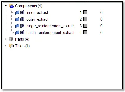
Step-3: Once we have the component we wish to work on, the next step is to delete the solids present in the component as we only need a surface for the further steps. Go to Delete entities < Solids < All to delete every solid present in the CAD data.
Step-4: Go to Geometry
Procedure for outer hood and latch:
Step-5: After creating the mid surface first step should be to clean up the geometry. As mentioned earlier, this step can determine the quality of the mesh to a greater extent. Thus, we should make use of
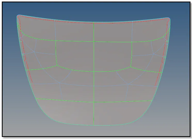
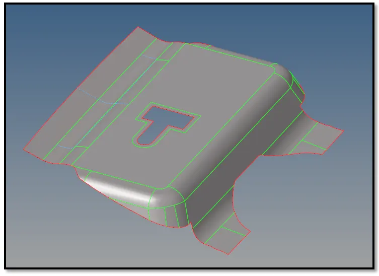
Step-6: Once we are done with geometry clean-up, we should go to 2D< Automesh (choose element size as 5 units and mixed elements) to create mesh on the mid surface of the component. The odds of getting a good mesh in this step depend on how good our previous step was.
Step-7: As the mesh created by the auto mesh option needs some clean-up, we mesh the component (one patch at a time) again using the auto mesh option. We can use the rebuild mesh option too.
Step-8: Once we are satisfied with the quality of the mesh, we should check the quality index of the mesh. This option shows us the elements which fail the criteria that we can set according to the given requirement. Then we have to work on each of the failed elements until we get zero failed elements.
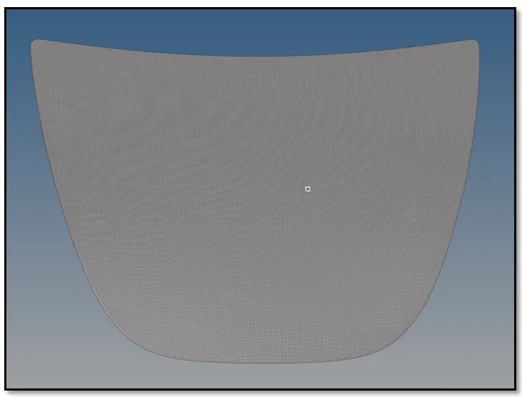
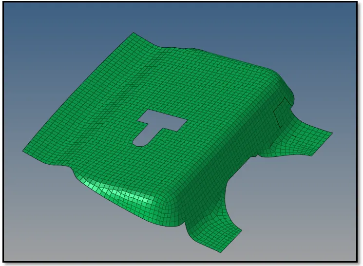
Procedure for hinge reinforcement:
Step-5: After creating a mid surface for this component we can delete one of the reinforcements. Thus, go to Delete entities< delete surface and delete any one of the reinforcement.
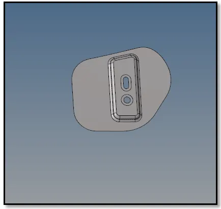
Step-6: As now we only have one reinforcement, we have to follow steps 5, 6, 7, and 8 mentioned above.
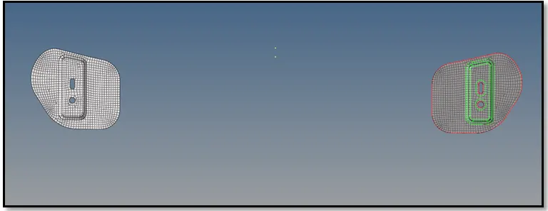
Step-7: Once we get a good quality of the mesh, we can go to Tools< reflect elements to reflect the mesh on the other side. This tool works as a mirror command.
Procedure for the inner hood panel:
Step-5: After creating mid surface we can delete one half of the surface that is perfectly symmetric so that we can reduce the work and time needed to mesh this component.
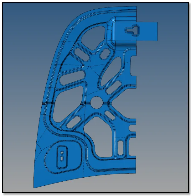
Step-6: We again have to follow the same steps that are 5, 6, 7, and 8 mentioned above to get a good quality mesh. However, we must put effort to clean up the geometry of this component as it has a lot of fillets and rounds which can result in a bad mesh.
Step-7: Once we are satisfied with the mesh on one half of the panel we can reflect the required elements on the other side to get an entire inner hood panel.
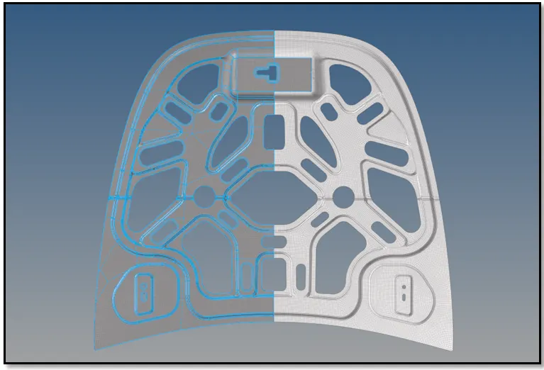
CONCLUSION: Created mesh on various components of the hood panel.