Creation of 1D Connectors
CREATION OF 1D CONNECTORS CHALLENGE
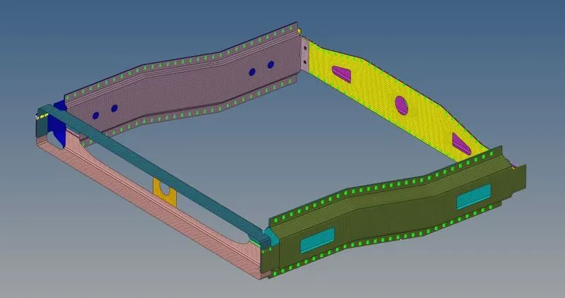
AIM: To mesh the components in the given assembly and connect them amongst themselves using the connectors in HyperMesh.
PROBLEM STATEMENT:
THEORY:
CONNECTORS: They are geometric entities (not FE) primarily used to create spot- and seam welds, but also used to create adhesives, bolts, and masses. They are simply a database of information defining specific requests for connections at specific locations. They are a medium to create both solver-independent and/or solver-dependent connections between geometric and/or FE entities.
Connectors are important because:
- They ensure the connectivity between different parts in a model
- They represent the geometric connection in terms of FEA
- They transmit the force between the parts which are connected together.
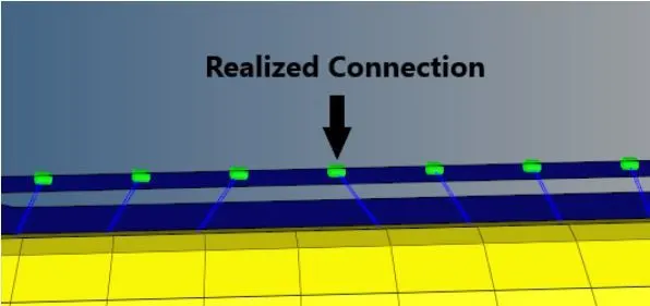
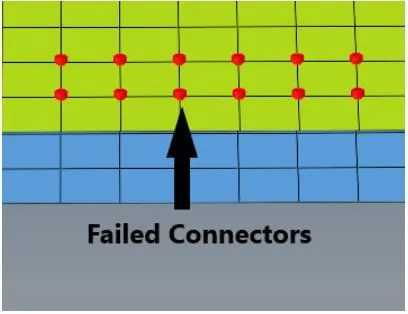
STATES OF CONNECTORS: There are three different connector states.
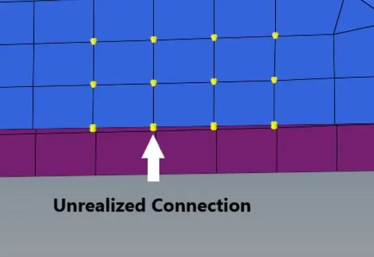
- Yellow represents an unrealized connector. They are created when there is a newly created or imported connector before the first realization, editing the connector definition (i.e. add or delete a link entity from the connector), the connector removes the welds it created and reverts back to an unrealized state, or manual unrealization.
- Green represents a successfully realized connector. A realized connector will be considered as the successful representation of a CAD model in the preprocessing stage. Then it will be moved into the solver side.
- Red represent failed connector: If the creation of the FE representation is unsuccessful (due to low tolerance, insufficient link entities, etc.) the connector icon is displayed as failed (red).
COMMONLY USED CONNECTORS IN HYPERMESH:
- Seam Weld
- SpotWeld
- Adhesive
- Bolt Connectors
SEAM WELD: Seam welding is the joining of workpieces made of similar or dissimilar materials along a continuous seam. Seam welding can be broken down into two main techniques, resistance seam welding, and friction seam welding.
SPOT WELD: This welding process is used primarily for welding two or more metal sheets together by applying pressure and heat from an electric current to the weld area. It works by contacting copper alloy electrodes to the sheet surfaces, whereby pressure and electric current are applied and heat is generated by the passage of current through resistive materials such as low carbon steels.
ADHESIVE: It is any substance that is capable of holding materials together in a functional manner by a surface attachment that resists separation. The use of automotive adhesives & sealants is widespread, from something as small as a sensor to something as large as a vehicle chassis. Many high-performance cars are produced with lightweight composite materials to keep the weight of the vehicle minimal. These composite materials are unable to be welded and the use of mechanical fasteners adds to the vehicle weight, as well as being unsightly and at risk of vibrating loose. Structural adhesives are very much a favorite amongst automotive industry professionals, as they allow different types of material to be joined together easily
BOLT: A bolt is a mechanical fastener with a threaded shaft. Bolts are closely related to screws, which are also mechanical fasteners with threaded shafts. These types of fasteners are typically inserted through two parts, with aligned holes.
PROCEDURE:
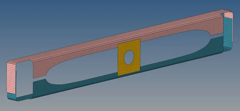
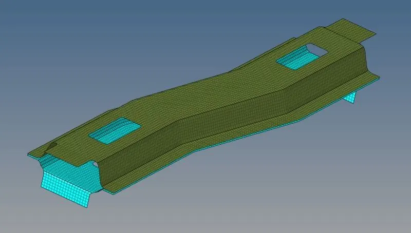
MESHING OF THE GIVEN COMPONENT: As the connectors have to be deployed in the FE model of the component, cleaning the given component and meshing it while ensuring good quality and proper flow is of utmost importance to get good connector representation between the elements. There are 9 components in the given assembly and to ensure proper mesh on each of them I meshed them individually.
- Hide all components except one. Start cleaning the geometry using clean-up tools given under Geometry< quick edit panel or press F11. Try to divide the geometry into square or rectangular patches in order to get quads in that region.
- Go to 2D< automesh panel or press F12. We can select the entire component at once and mesh it, but to have better control over the mesh flow I preferred to mesh each of the patches in the component. Also, it is not a complex geometry so we get a good quality mesh in the first attempt.
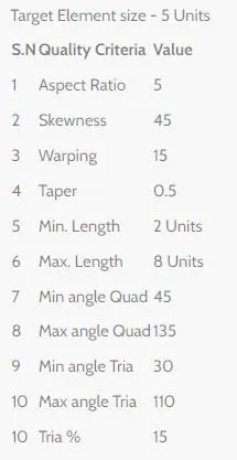
- Finalizing the mesh. Go to 2D< quality index and Tools< check elements to check if all the elements in the mesh are following the given criteria. Clean the elements which do not follow the given criteria.
- Repeat the same procedure for all the components to get the FE model for the given assembly.
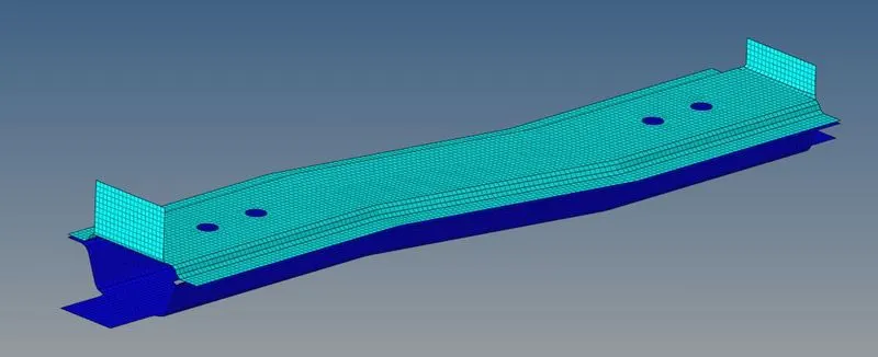
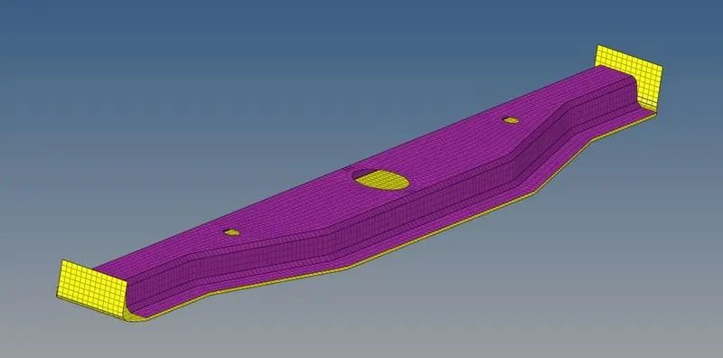
DEPLOYING THE CONNECTORS:
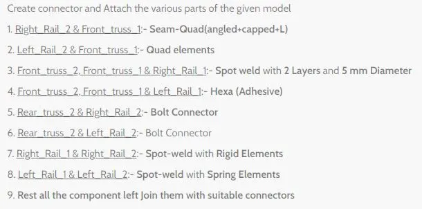
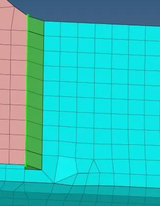
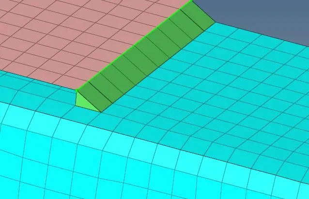
Seam quad (angled+capped+L) between Right rail 2 and front truss 1:
- Select 1D/2D<Connectors<Seam
- Now select the location, where the Weld has to be created, by clicking the node list.
- Tick the checkbox of retain nodes option, to retain the position of the nodes, while creating and realizing a connector.
- Specify the spacing value equal to the target element length and select the comps option under "connect what'', in order to create the weld between those two components.
- Specify the tolerance value, based on the distance between the two components.
- Select the type as seam-quad (angled+capped+L).
- Click on the create button, to create the seam weld.

The following image shows the aforementioned seam weld, but as we can see that it hampered the mesh quality. In order to get proper mesh flow again, we must use tools like aligning nodes and making the mesh proper again as shown in the 2nd image.
Quad elements between Left rail 2 and Front truss 1:
- Select 1D/2D<Connectors<Seam
- Now select the location, where the Weld has to be created, by clicking the node list.
- Tick the checkbox of retain nodes option, to retain the position of the nodes, while creating and realizing a connector.
- Specify the spacing value equal to the target element length and select the comps option under "connect what'', in order to create the weld between those two components.
- Specify the tolerance value, based on the distance between the two components.
- Select the type as
- Click on the create button, to create the seam weld.

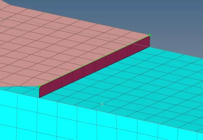
Spot weld with 2 layers and 5mm diameter between Front truss 2, Front truss 1, and Right rail 1:
- Select 1D/2D<Connectors<Spot
- Now select the location, where the Weld has to be created, by clicking the node list.
- Select the comps option under "connect what'', in order to create the weld between those two components.
- Specify the tolerance value, based on the distance between the two components.
- Select the type as
- Keep the number of layers as 2 and specify the diameter as 5mm.
- Click on the create button, to create the seam weld.

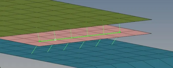
Hexa (Adhesive) between Front truss 1, Front truss 2 and Left rail 1:
- Select 1D/2D<Connectors<Seam
- Now select the location, where the Weld has to be created, by clicking the node list.
- Tick the checkbox of retain joints option, to retain the position of the nodes, while creating and realizing a connector.
- Specify the spacing value equal to the target element length and select the comps option under "connect what'', in order to create the weld between those two components.
- Specify the tolerance value, based on the distance between the two components.
- Select the type as Hexa (adhesives).
- Specify the Stripes value and Coat value to change the number of hexa elements along its width and thickness respectively.
- Specify the width value to increase or decrease the representation of the hexa elements.
- Click on the create button, to create the seam weld.

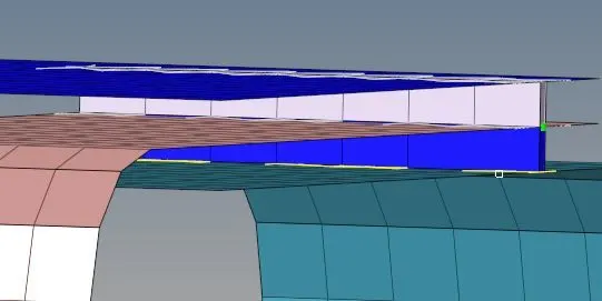
Bolt connectors between Rear truss 2 & right rail 2 and right truss 2 & left rail2:
- Select 1D/2D<Connectors<Bolt
- Select the comps option under "connect what'', in order to create the weld between those two components.
- Specify the tolerance value, based on the distance between the two components.
- Select the type as Bolt (general).
- In order to make the connector realized, we have to select create a hole if none option as there are no pre-existing holes in these FE models.
- Click on the create button, to create the seam weld.

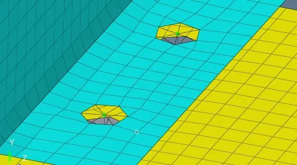
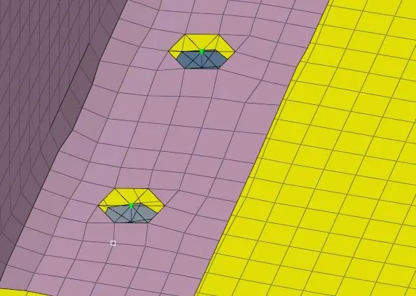
Spot weld with rigid elements between Right rail 1 and right rail 2:
- Select 1D/2D<Connectors<Spot
- Now select the location, where the Weld has to be created, by clicking the node list.
- Select the comps option under "connect what'', in order to create the weld between those two components.
- Specify the tolerance value, based on the distance between the two components.
- Select the type as
- Click on the create button, to create the seam weld.

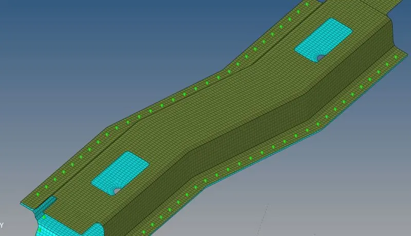
Spot weld with spring elements between left rail 1 and left rail 2:
- Select 1D/2D<Connectors<Spot
- Now select the location, where the Weld has to be created, by clicking the node list.
- Select the comps option under "connect what'', in order to create the weld between those two components.
- Specify the tolerance value, based on the distance between the two components.
- Select the type as
- Click on the create button, to create the seam weld.

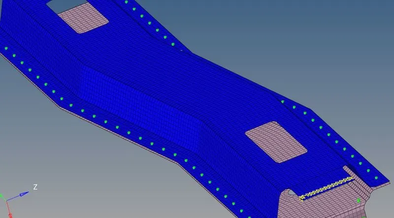
For all other components that are not mentioned in the problem statement, I have used the already mentioned connectors to establish a connection between them.
CONCLUSION: I have successfully implemented the knowledge that I have acquired through the previous week's exercise to mesh the given components and I have also deployed all the given and necessary connectors between all the FE models.