Core & Cavity Design
AIM: TO MAKE CORE AND CAVITY FOR SWITCH BEZEL.
INTRODUCTION:
CORE: The fixed half of the mold is core. It has the projection in it.
CAVITY: The movable half of the mold is cavity. It had the depression in it.
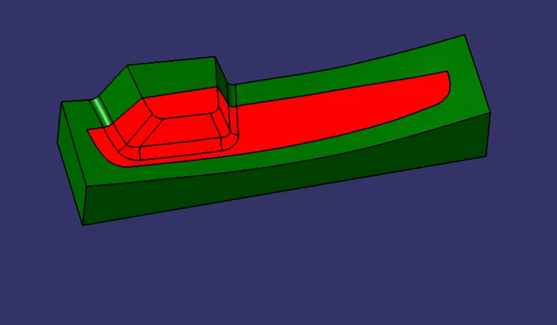
HERE CORE HALF WILL BE SEEN FROM THE GREEN SURFACES THAT IS FROM BELOW AND CAVITY HALF FROM RED SURFACES.

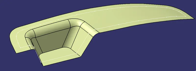
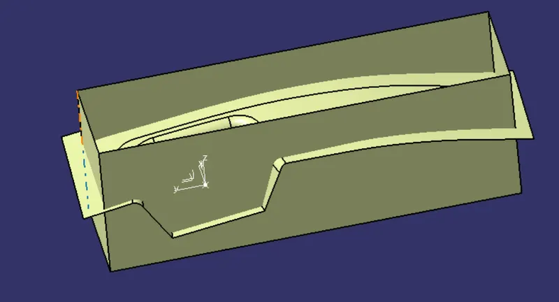
PARTING SURFACE: The surface parting the core and cavity is called parting surface. It is the biggest projection outline of the part.
APPROACH:
FOR PARTING SURFACE:
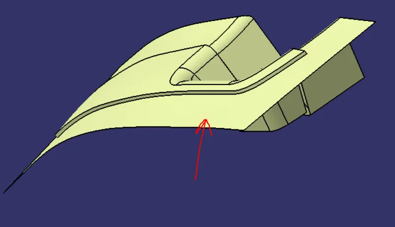
- Trim class-A and class-C surfaces together.
- Trim it with class-B but this time keep the outside part in the model.
- Split the surface obtained with the parting line.
FOR PARTING LINE:
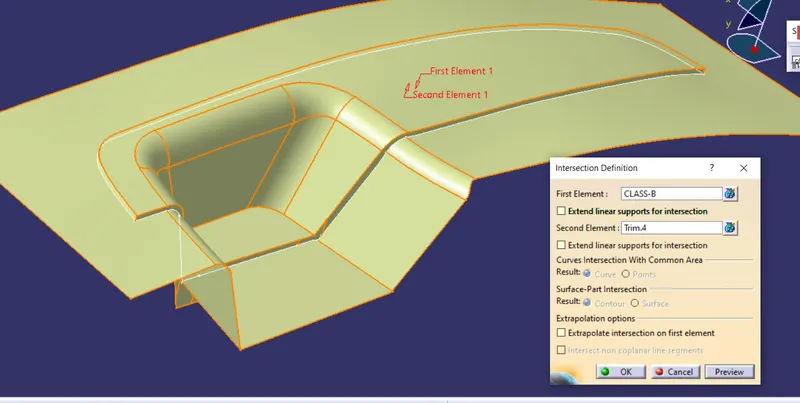
- Intersect class-B and class-C surface.
- We get our parting line.
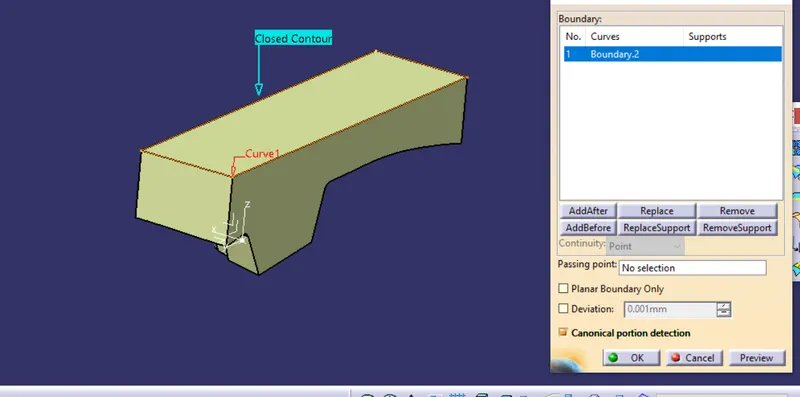
FOR CORE BLOCK:
- On the top view draw a rectangle and it should be within the parting surface.
- Extrude it.
- Trim with parting surface.
- Fill it and join together.
- Close the surfaces.
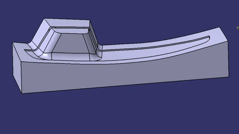
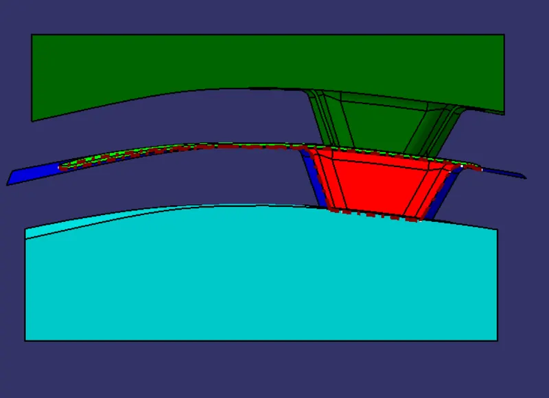
HERE, THE GREEN BLOCK IS THE CORE BLOCK AND THE RED ONE IS THE COMPONENT.
FOR CAVITY BLOCK:
- Use the earlier extrude.
- Trim it with the parting surface keeping the lower half.
- Fill it.
- Join it and close it.
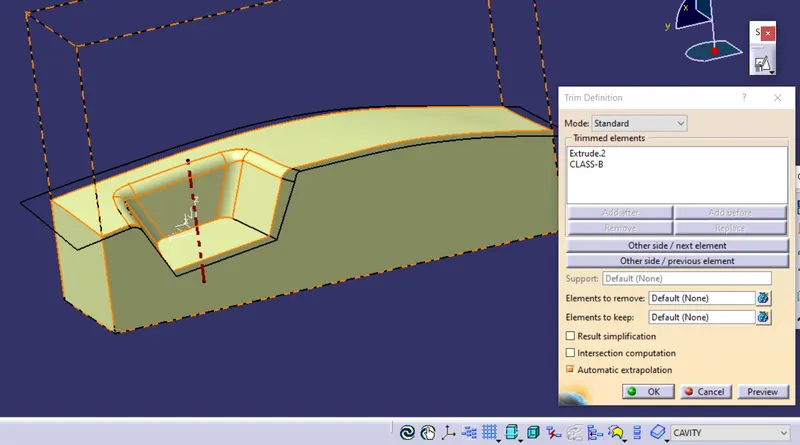
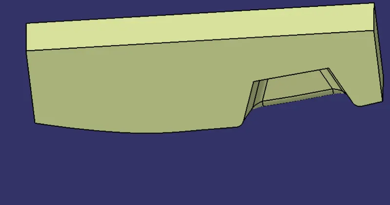
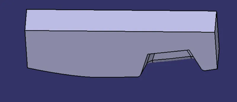
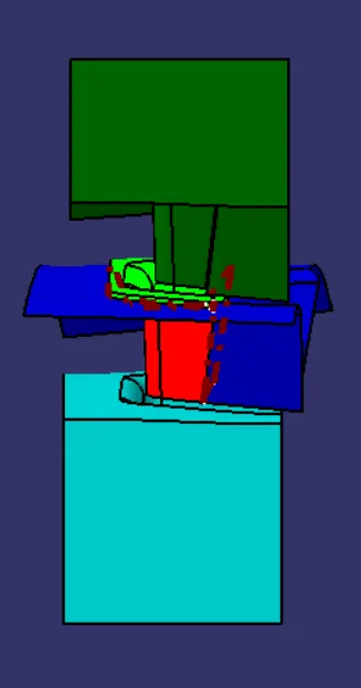
HERE GREEN IS THE CORE BLOCK AND SEAN BLOCK IS CAVITY.
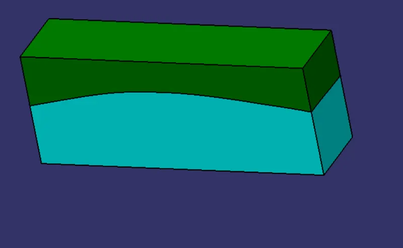
THE MARKED GAP IS WHERE THE COMPONENT WOULD BE MOLDED.
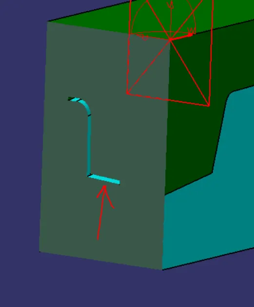
THE THICK BLUE LINE IS PARTING SURFACE
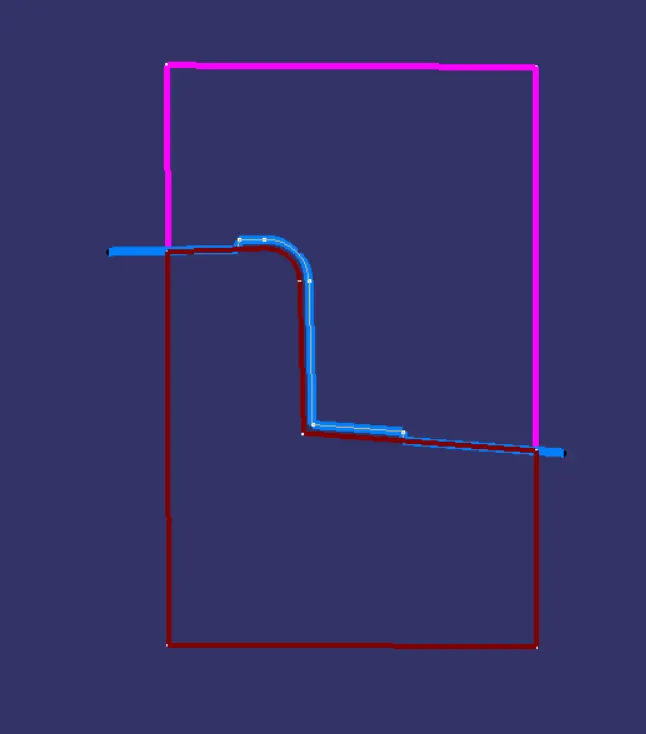
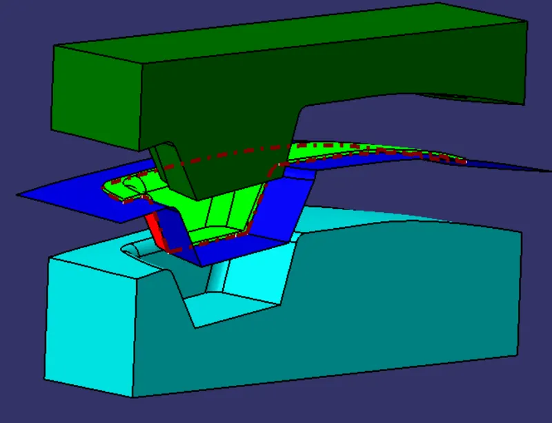
DOTTED BROWN LINE IS PARTING LINE
BLUE SURFACE IS PARTING SURFACE
GREEN BLOCK IS CORE
SEAN BLOCK IS CAVITY
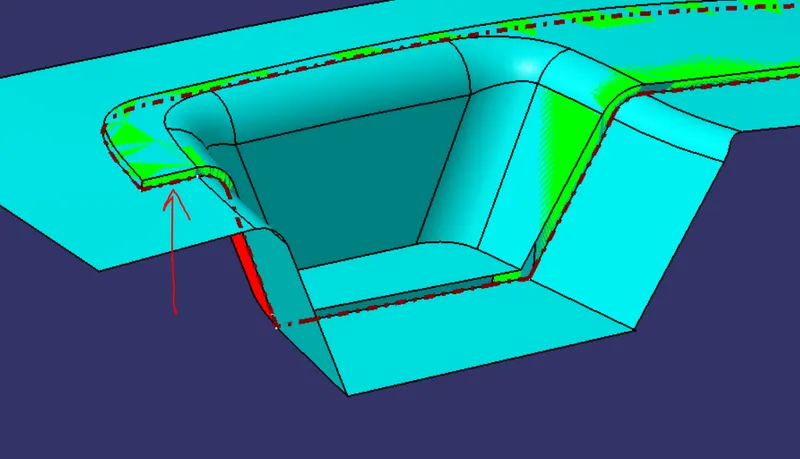
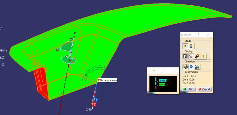
DRAFT ANALYSIS ON CLASS-A SURFACE
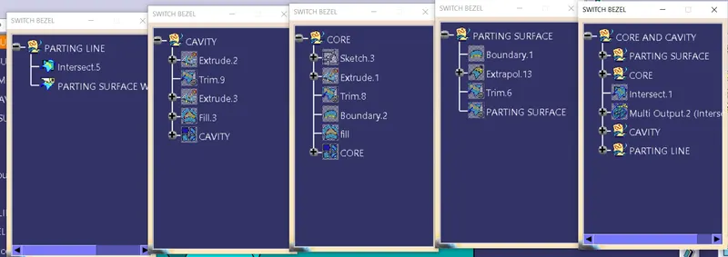
TREE STRUCTURE: