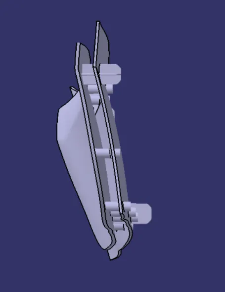
Door Applique Design with Engineering Features
DOOR APPLIQUE DESIGN WITH ENGINEERING FEATURES:
AIM: To make a door appliqué from the provided class-A surface.
THEORY:
While making a complete model of anything, we have to deal with the numerous components which have to be locked, fastened, welded etc with each other so that they do not move from their desired position. Any component we make has 12 degree of freedom. We have to restrict at least 11 degree of freedom. To do so we use various engineering features according to the 3-2-1 principle. In this, we will look into
- Locators
- Heat stakes
3-2-1 PRINCIPLE: The 3-2-1 principle states that the six locators are sufficient to restrict the required degree of freedom of any work piece. In this, motion is restricted using clamps and locators. A three pin base can restrict five motions and six pins restrict nine motions.
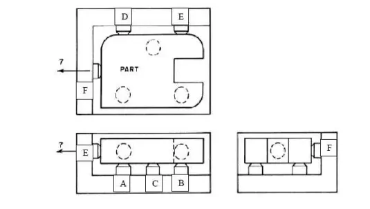
HEAT STAKING: Heat Staking is a pulsed-heat process to join two or more parts out of which one at least is made of plastic. The process is to deform the plastic material using heat and force at a set process time. The bond is made by partially de-forming the plastic part in order to fix the other.
APPROACH
- Make the tooling axis
- Do draft analysis
- Make class-B surface
- Make class-C surface
- Make surface model from them
- Make solid model from the surface model
- Create locators
- Create heat stakes.
TOOLING AXIS AND DRAFT ANALYSIS:
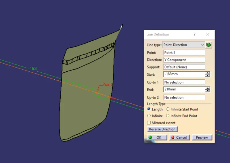
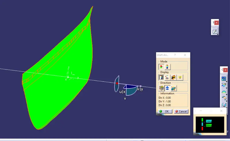
- By looking at the model we can make a dummy axis perpendicular to the faces. In this case it is y-axis.
- Go to draft analysis and align the compass at this dummy tooling axis.
- Click on the model and see the surfaces which are failing the analysis.
RESULT OF ANALYSIS: All the faces of class-A surface are green.
CONCLUSION: The chosen axis is correct and it is our main tooling axis. The surface has drafts and it will be ejected properly.
BISECTING METHOD FOR CREATION OF TOOLING AXIS:
- Make an axis system and intersect the model to be analyzed with the required plane of the system. For example is we are confused about the two faces of the model if they have draft or not and those face seems to be vertical then we will intersect the front plane with the model.
- Once we get the intersection line, we will make lines on the lines which represent those surfaces.
- Then we will bisect those lines to get one line.
- This will be the tooling axis for those faces only.
- Then we will do the similar process for the other two parallel faces which are perpendicular to the earlier faces so that we get two lines which intersect each other.
- Once we get two lines which are tooling axis for two different pair of faces, we will make a line which bisects these two lines.
- This new line will be our required tooling axis.
UNDERSTANDING DRAFT ANALYSIS:
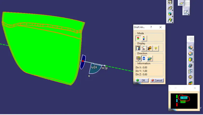
There are three different colors for three different values here. We can change the values and colors both. Let us understand what these values and colors are. And also let us look into method if we don’t get desired results in our dummy axis.
In color scale we can change values for corresponding colors.
- The top most value means that the color corresponding to it will denote the faces which have more value than that in the column.
- The middle value means that the color corresponding to it will denote the faces which have value between the top value and this value.
- The lower most value means that the color corresponding to it will denote faces which have lower value than that of the mentioned here.
These values are the draft values with respect to the tooling axis. For better understanding we have given green and 2.9 which we want. Blue for 0 and red for negative values.
IMAGES (IN ORDER OF THE STEPS ABOVE)
1.
2.
SIMILAR DRAFT ANALYSIS ON THE MODEL
CREATING CLASS-B SURFACE
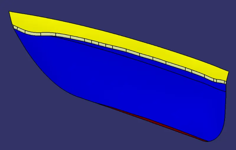
- The surfaces to extract from class-A are shown in the image with different colors.
- Extract those surfaces and offset them at 2.5mm. This value is the thickness of the component.
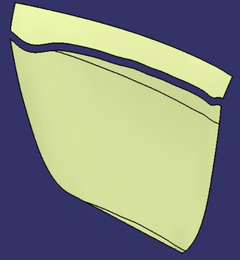
- Extrapolate the required surfaces and trim them together.
- Give the fillet to the class-B surface. This value should be taken from class-A after subtracting 2.5mm from it.
IMAGES (IN ORDER OF THE STEPS ABOVE)
1.
2.
3.
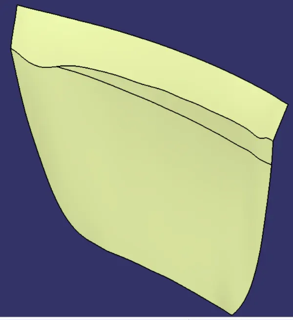
4.
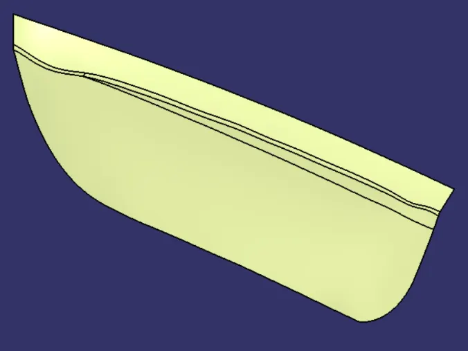
CREATING CLASS-C SURFACE
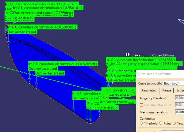
- Extract the boundary of the class-A surface.
- Smoothen, this curve.
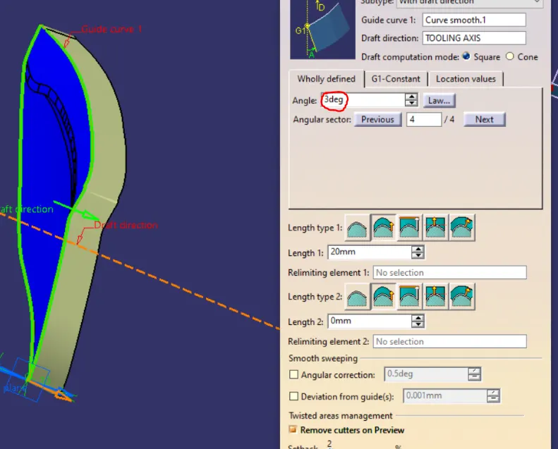
- Use sweep command with draft direction on this curve and give a value of 3deg outwards.
IMAGES (IN ORDER OF THE STEPS ABOVE)
CREATING DOOR APPLIQUE
- Trim or join class-A and class-C surfaces together.
- Trim this surface with class-B surface.
- Make sure there are no boundaries or in other words make sure that the surface model is closed.
- Go to part design workbench and close the model.
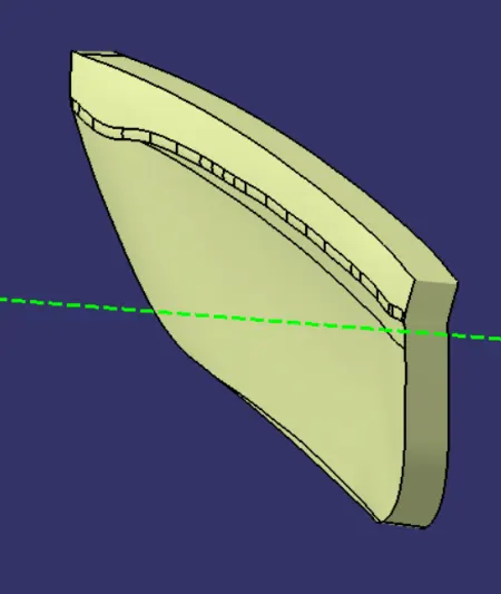
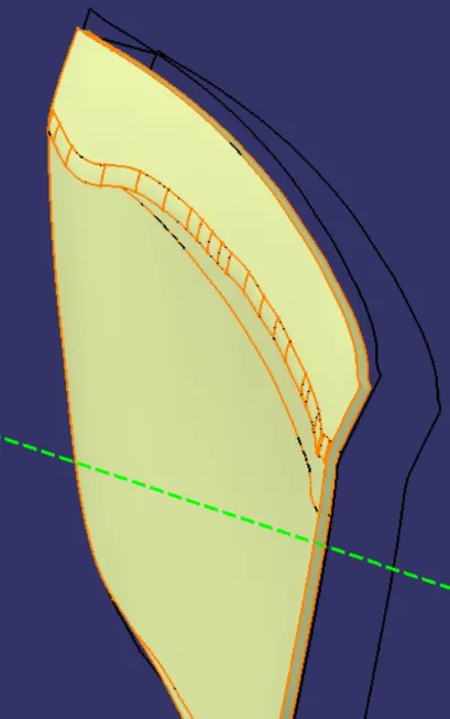
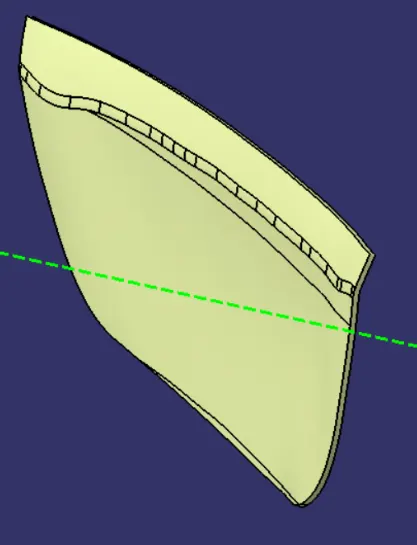
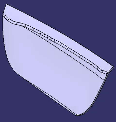
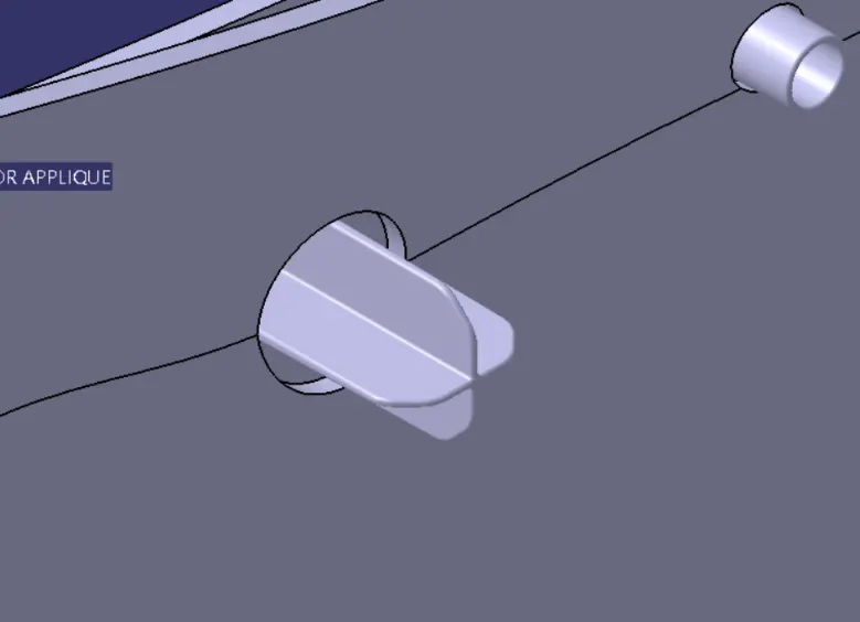
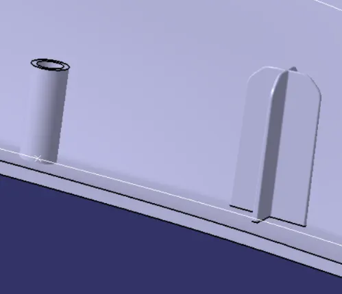
DESIGNING LOCATORS:
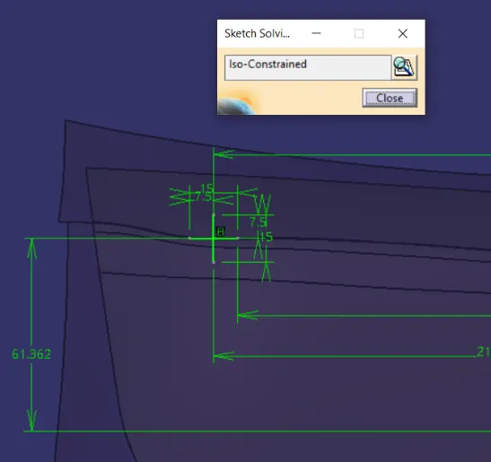
- Sketch on the B side of the model. Choose the location for the locators.
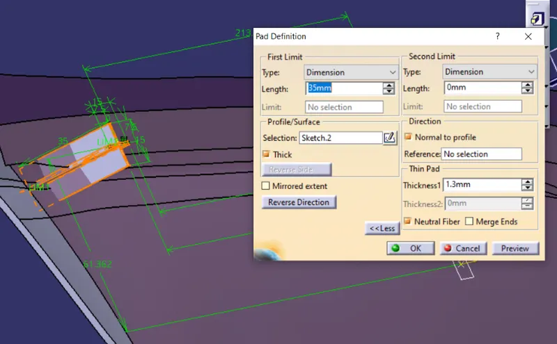
- Pad the sketch using thick feature with neutral fiber toggled.
- Make sure to follow the design rules for the ribs.
- Thickness should be about 0.4*t.
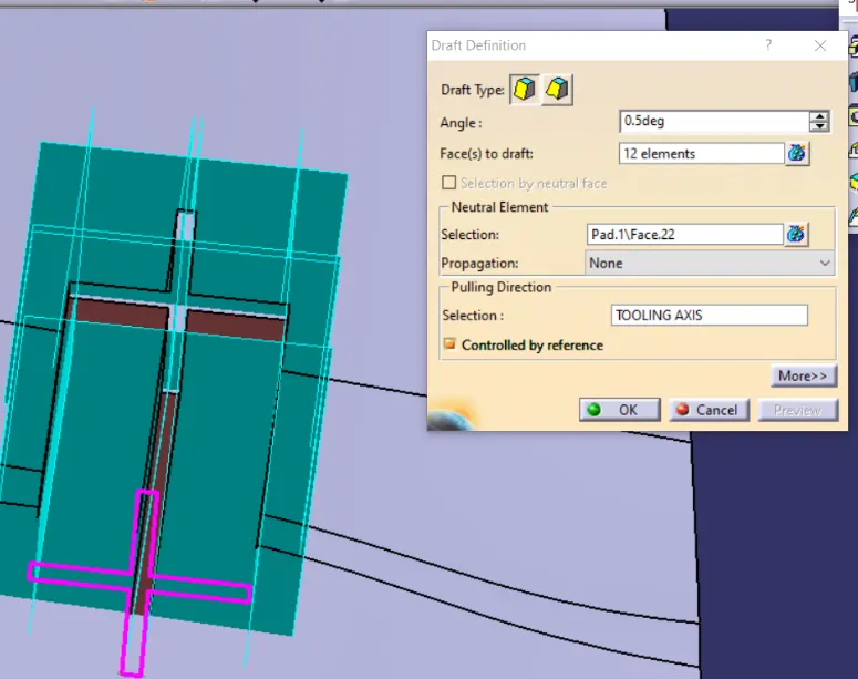
- Give draft of around 0.5deg on each face.
- Give entry chamfer of about 3mm*45deg.
- Fillet every edge of the locator with about 0.3mm.
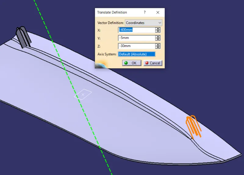
- Copy the locator, past special with link and translate it to other locations.
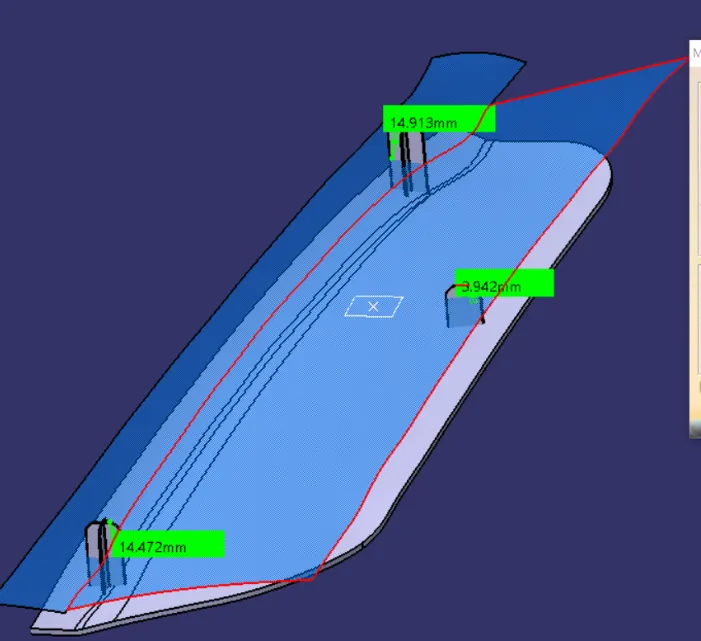
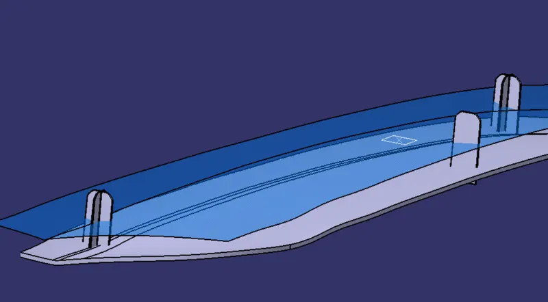
- Make sure that every locator has same distance between the top face and the surface to be joined.
- Add/union-trim all the locators with the solid appliqué model.
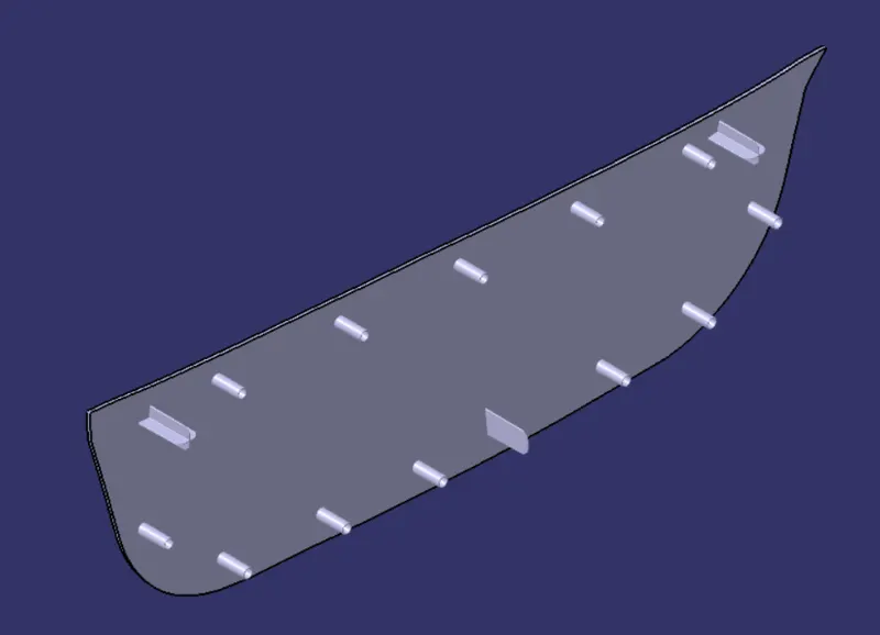
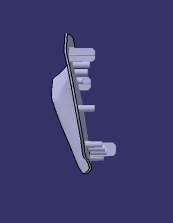
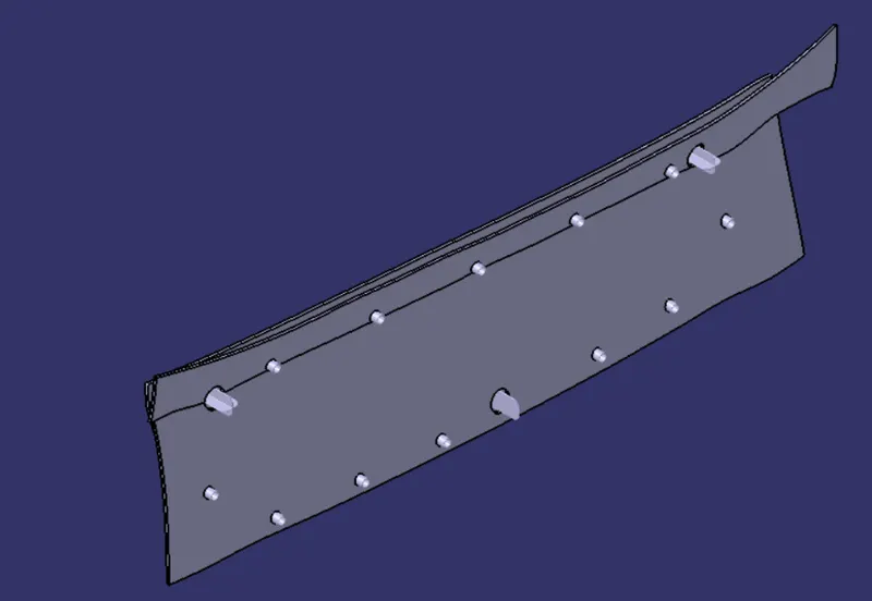
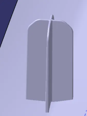
As we need three locators on the base we will translate it to other locations using translate command. Also there are two types of locators used here, 4-way locators and 2-way locators. Design procedure is same for both of them.
IMAGES (IN ORDER OF THE STEPS ABOVE)
1.
2.
5.
7.
8.
9.
DESIGNING HEAT STAKES:
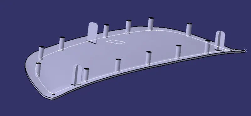
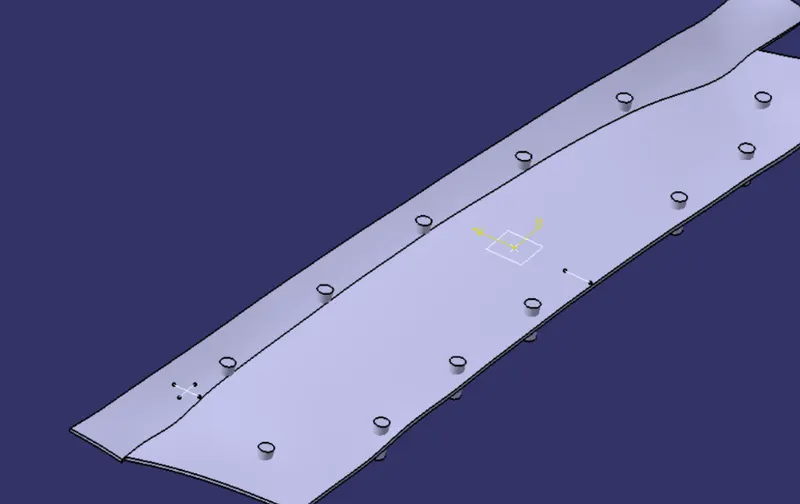
- Extract class-A surface and offset it at 2.5mm. Then extract the boundaries of the surface. Two separate boundaries were extracted. Make a parallel curve for both the boundaries at about 15mm.
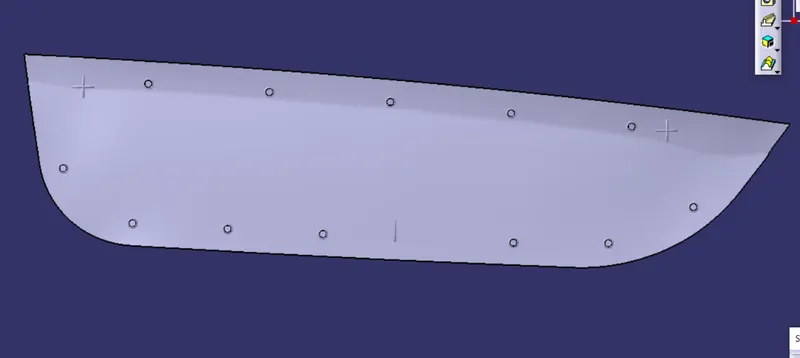
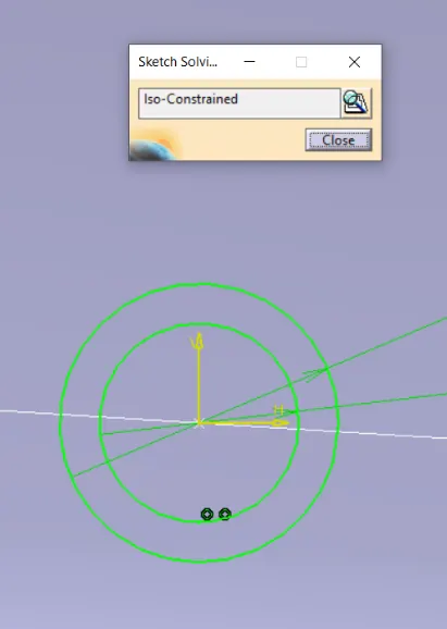
- Use points and planes repetition command and make points on the curve. These points represent the centre of the heat stakes. Make sure that no heat stake is located near the locator.
- Make the sketch at any one of the points and pad it. Use draft command with 0.5deg draft.
- Now we have to make the heat stakes at every point, so we copy the original, paste special with link and translate point to point. We have to repeat this for every point.
- Once completed, use Boolean-operation add to make them a single body in a different body. Make a copy of this body and hide it as we will need it later.
- Use Boolean-operation add/union-Trim it to the main appliqué body.
IMAGES (IN ORDER OF THE STEPS ABOVE)

CREATING ENTRY POINTS FOR THE FEATURES ON THE COUNTERPART:
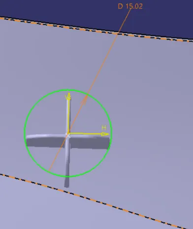
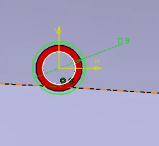
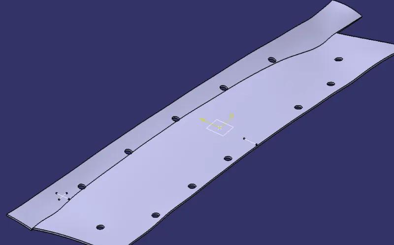
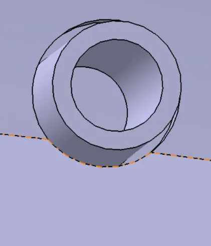
Clearance has to be given while creating hole in the counterpart. The clearance value for locator is 0.1mm each side while for heat stake is 0.5mm each side. A little deviation is considerable.
- Copy paste the locator’s sketch and make everything as reference. Make a circle with proper dimension. It should be 0.1mm greater on all sides.
- Pad this and give it a draft.
- As we have translated the locator to other location their sketch is not available. So make a point on the top surface of the locator and make a sketch there and follow the same procedure.
- Once completed, remove it from counterpart using Boolean-operation. Ensure that it has clearance of around 0.1mm. It might be different as we are giving draft. In this case modify the sketch accordingly.
- Unhide the earlier hidden heat steak assembly. Edit the parent sketch and make it a cylinder with bigger dimension. 0.5mm clearance has to be given.
- This will change every other heat stakes. Give this a draft too. And use Boolean operation to remove it from the counterpart.
- Thus we have created entry holes for the features.
IMAGES (IN ORDER OF THE STEPS ABOVE)
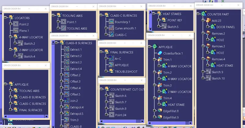
TREE-STRUCTURE:
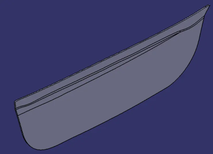
IMAGES OF THE MODEL
1. BEFORE B-SIDE FEATURES:
2. AFTER B-SIDE FEATURES: