Design of BIW Fixture
Design of BIW Fixture
OBJECTIVE: To design a complete BIW fixture for the given panels and do necessary detailing on the model.
ABSTRACT: In automotive industry, a lot of processes are followed to make a single panel and further operations are performed on that panel and other panels to get an automobile. The role of BIW fixture design engineer is to make fixtures for the panels so that they can be worked on. A fixture is a work holding device that holds support and locates the work piece in the desired position to perform any operation.
In this project I have carried over the previously designed clamp units, pin units, rest units and made necessary changes. As there are 5 panels as input, a fixture should be designed such that all the panels are constrained, so I have designed pin-clamp units for small panels as it will cost less than individual units and require less space. I have designed rough locators following industry rules and in the last worked on small details of the model. This report contains basic definition and explanation of the fixture, units its parts and process followed to design the base unit.
SOFTWARE USED: CATIA V5
INTRODUCTION:
FIXTURE: A fixture is a work holding device that holds support and locates the work piece in a desired position to perform any operation. Thus the main purpose of the fixture is to hold and support the work piece during machining operation and to provide repeatability, accuracy and interchangeability in the manufacturing of the products.
A BIW fixture is an assembly of units. A unit is a device which has unique function and is a component of a fixture. Components of units differ from unit to unit. In general a BIW fixture consists of following units:
- Pin unit
- Clamp unit
- Rest unit
- Rough locator unit
- Sensor unit
- Base unit
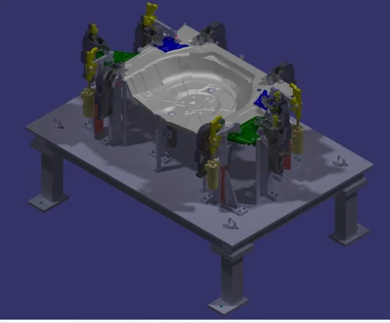
FIG. FIXTURE DESIGNED FOR THE PROJECT
3-2-1 PRINCIPLE: It states that the six locators are sufficient to restrict the required degree of freedom of any work piece. In this, motion is restricted using clamps and locators. A three-pin base can restrict five motions and six pins restrict nine motions. Let us understand 3-2-1 principle in detail.
When any work piece is not clamped or held, it can move or rotate in any direction and along any axis. We can list its movements as:
- Translational motion along x-axis.
- Translational motion along y-axis.
- Translational motion along z-axis.
- Rotational motion along x-axis.
- Rotational motion along y-axis.
- Rotational motion along y-axis.
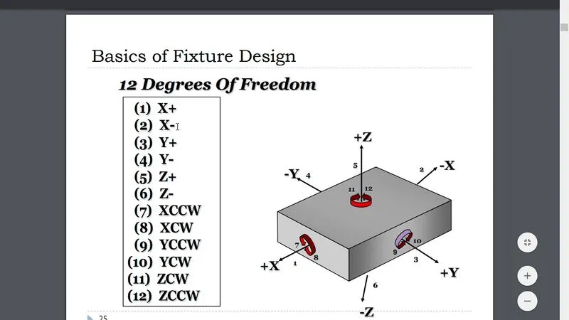
FIG. DEGREES OF FREEDOM
These are not just 6 but 12 as its motion will be along positive and negative directions and along clockwise and counter clockwise direction. But if we were to perform any operation on that work piece we must restrict the movements in order to perform the task without any mistakes. This can be achieved by 3-2-1 principle. In 3-2-1 principle we make use of locating pins in the given order to fix it on a fixture:
- 3 pins are located on the bottom side of the component. These pins constrain the translational motion of the body in z direction and rotational motion along x-axis and y-axis. Thus 3 degrees are restricted. But the body still can rotate along z-axis and translate in x-axis and y-axis.
- 2 pins are located on the back side of the component. These pins constrain the translational motion along x-axis and rotational motion along z-axis. Thus we have constrained 5 degrees in total. But translation along y-axis is still possible.
- 1 pin located on the adjacent side of the 2 pins we can constrain the last degree that is translation along y-axis.
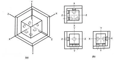
FIG. LOCATING PINS
Thus, a fixture locates the work piece with the help of its various units, Pin unit and clamp unit in general. All the degrees of freedom are restricted using these two units. In clamp unit, we use clamping Mylar and Rest Mylar to locate the panel. Here we are doing following things:
- Restricting the upward and downward motion that is movement along z-axis.
- Restricting clockwise and counter clockwise rotation along x-axis.
- Restricting clockwise and counter clockwise rotation along y-axis.
Thus out of 6, we are restricting 3 degrees of freedom when we clamp the panel. Similarly, when we locate the panel with locating pins we:
- Restrict the translational movement along x-axis.
- Restrict the translational movement along y-axis.
- Restrict the rotational movement along x-axis.
- Restrict the rotational movement along y-axis.
WELD STUDY: Weld study is provided by the customer beforehand to convey the information such as the type of weld gun to be used, location of weld matrix and weld points. Type of weld gun used for the operation depends on the size and the thickness of the part. As the customer has already decided these things so it is easy for him to do this study and provide us the data so that we can make use of this for designing purposes. Weld location and weld matrix has data of geo spot and weld spots. This data tells us exactly where and which type of weld will be applied. It shows the geo spots and re-spots with spheres with different colors.
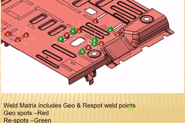
FIG. WELD STUDY
CLAMP PLAN: The customer provides the clamp plan which consists of the position of the clamp, pins, rests and dump etc. It has the exact coordinates of these components and in addition it also has the hole’s dimensions and tolerances. As this is a critical input data, it must not be modified on own. In case the spot for weld and the clamp position is nearby and it may create problem later and there is need to change the position of the clamp, the same must be done so with the permission of the customer as it will be easy for the customer to make changes from his side also.
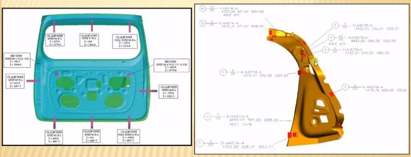
FIG. CLAMP PLAN
3D FINISHING: 3D finishing is a process where the design is being completely finish and to be ready for the final simulation and 2D detailing. This is basically the finally step and after this the design is freeze.
Following steps are taken care of while finishing the design:
- Hole concentricity and hole size: The parts which are the be fastened together should have concentric clearance holes and threaded holes with corresponding sizes.
- Machining area: The surfaces which are to be machined should be represented with proper coloring.
- Nominality: The coordinates of the units should not be in decimal. All the units should be edited with respect to base in order to get nominal dimension. Pin units are exception for this as the locating hole is input from the company and should not be edited unnecessarily.
- Hole coloring standard: The fastening holes and dowel holes should be given standard colors. Dowel hole is navy blue, clearance hole is aqua and threaded hole is yellow in color.
- Pneumatic lay-outing: Pneumatic channeling should be provided on the base plate for all the connection which would connect pneumatic cylinders and solenoid valve box.
- Gaps checking: There should be proper and minimum gaps between every surface. That is between panel and units, units and units, weld gun and units etc.
- Fastener implementation: Proper fasteners must be installed in the units from the library of the software. Every standard fastener is available in the library.
- Avoiding clash between different parts: In a fixture, every unit and every part must have minimum gap between them and should not clash or hamper the working of the other unit. This applies to the Gun study also. Weld gun position is to be such that the gun does not clash with any of the part. If it clashes, then the position of the gun should be manipulated or the unit should be edited or manipulated.
- Mylar splitting as per panel profile: In case of clamp unit, if we copy a Mylar from one location to other, the Mylar must be split again with the present surface in order to properly cut the Mylar.
- Proper renaming of parts/assemblies as per the standard: The naming of the parts, components and products should be according to the standard so that another designer is able to understand and work on the project.
UNITS DESIGNED IN THE FIXTURE
Retractable pin unit: A pin unit is used to locate the work piece. Retractable pin unit is a type of pin unit which has freedom to move up and down as the combination of locating pin, pin retainer, L block or locating pin alone or locating pin and pin retainer is mounted on the retractable cylinder. It consists of the following parts:
- Locating pin
- Pin retainer (Optional)
- L block
- Two way shimming
- Blade (Optional)
- Retractable cylinder
- Riser
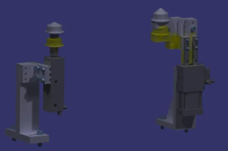
FIG. PIN UNITS DESIGNED FOR THE PROJECT
REST UNIT: The sole purpose of these types of units is to let the panel rest on it. It does not use any clamping force or any other force to fix the panel on it. This is a simple unit and can be combined with other units like pin units and clamp units. It consists of following parts:
- Rest Mylar (NC block)
- Shim pack
- Blade
- Riser
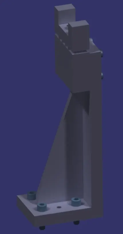
FIG. REST UNIT DESIGNED FOR THE PROJECT
CLAMP UNIT: A clamp unit is used to hold the panel at desired location and prevent it from unnecessary movements. A clamp plan is provided by the customer, which helps us to design the clamp unit as it consists of the location of clamping. For individual clamping, I have designed powered clamp unit which uses pneumatic powered cylinder. It consists of following parts:
- Clamp arm (Standard)
- Pneumatic clamp cylinder
- Shim pack
- Blade (Optional)
- Riser
- NC blocks
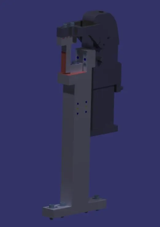
FIG. CLAMP UNIT DESIGNED FOR THE PROJECT
PIN-CLAMP UNIT: This unit is just a combination of pin unit and clamp unit. This can have various combinations. I have designed fixed pin unit with swivel cylinder and powered clamp. It consists of following parts:
- Locating pin
- Pin retainer
- L block
- Blade (Different for pin unit and Clamp unit)
- Shim packs
- NC blocks
- Clamp arm (Make part)
- Swivel cylinder
- Weld plates
- Stopper
- Riser
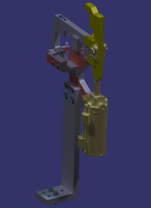
FIG. PIN-CLAMP UNIT DESIGNED FOR THE PROJECT
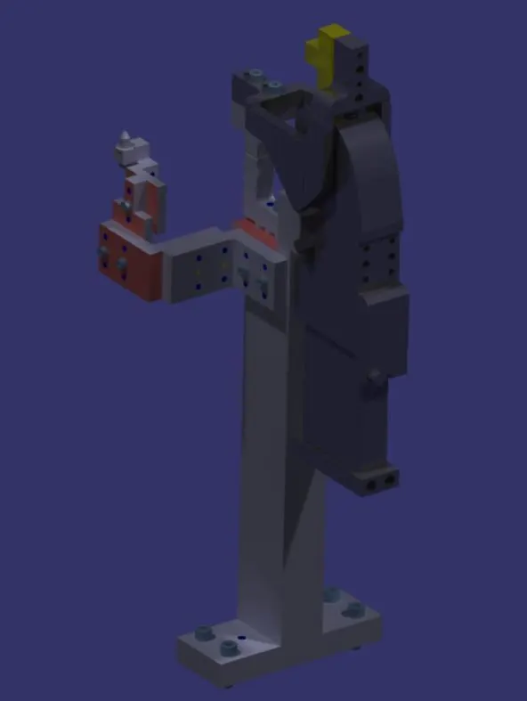
FIG. PIN-CLAMP UNIT DESIGNED FOR THE PROJECT
ROUGH LOCATORS: A rough locator is a part designed to guide the operator to locate the car panel on to the pins accordingly. A rough locator can be of standard part or make part. They have slot for adjustment and some space so that it starts guiding the panel in advance. They are used to guide the panel in correct position and orientation. They also help for proper Poka-Yoke. This is a Japanese term which means that the panel can only be placed in one orientation and if other orientations are possible for it, and then there is an error.
Fundamentals of rough locator design:
- Rough locators should be placed at the edges of the car panel which it has to guide.
- They have to be placed in the same angle of the car part edge with a minimum distance of 2-5mm from the edge of the car part.
- They should guide the panel in pin arresting direction
- They should start guiding the panel before 10-15mm to the start of the pin engagement.
- They should be designed with entry angle for car part entry.
- Rough locators should be designed with two slots to mount for easy adjustments.
- The slots should be in direction of car part guiding.
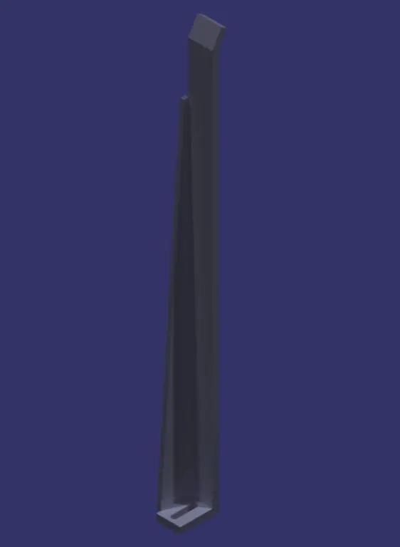
FIG. ROUGH LOCATOR DESIGNED FOR THE PROJECT
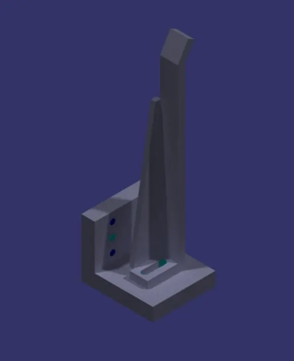
FIG. ROUGH LOCATOR DESIGNED FOR THE PROJECT
BASE UNIT: Base unit is the unit of the fixture which is designed as such so that other units of the fixture can be mounted on it. Apart from these units, other necessary tools like pneumatic valve box, trunking cable path will also be mounted on the base unit. It consists of following parts:
- Base plate
- Pedestal
- Trunking channel
- Valve box
- Eye bolt
- Floor plate
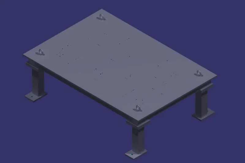
FIG. BASE UNIT DESIGNED FOR THE PROJECT
DESIGN APPROACH
Carry over the units from previous projects: As I have already designed various units for the same panel in different projects, I have used those units in this project. Retractable pin units and rest units were carried over without editing them further. Powered clamp unit, swivel clamp unit and base unit were also carried over but they were further edited and in some cases designed again.
Improving the input: As the input contains 5 panels together but they cannot be distinguished as they are in same color, the color was given to every panel was decided. Identical panels are given same color.
Constraining individual panels: The sole purpose of the fixture is to constrain the panel, every panel was constrained. For constraining a panel we need at least 2 pin units and 2 clamp units but designing 4 units was not feasible considering the space. So I have designed 2 pin clamps units instead. I have used carried over clamp units and made necessary changes on them to mount fixed pin unit and thus making a pin clamp unit. So for 4 small panels 2 pin clamp units are designed (each). For the main panel, powered clamp units are designed.
Designing rough locators: After designing and editing new units, rough locators were designed. Few were designed to be mounted on the riser of other units. But where this method was possible, long locaters are designed.
Editing base unit: Even if the base unit was carried over, many edits were done on it as many pin clamp units rough locator units were designed later. As the base unit must encompass every unit including the cylinder, previous base unit was unable to cover few cylinders, so the dimensions of the base plate have to be increased. Weld plates and pedestals were also moved accordingly. Also due to change in position of previous clamp units and addition of new units, new holes were created on the base plate.
3D finishing: Once entire fixture was designed, 3D finishing was done on the model in the exact pattern mentioned below:
- Checking Hole concentricity and hole size
- Depicting machining area in color
- Nominality
- Hole coloring standard
- Pneumatic lay-outing
- Gaps checking
- Fastener implementation
- Avoiding clash between different parts
- Mylar splitting as per panel profile
- Proper renaming of parts/assemblies as per the standard
FINAL MODEL
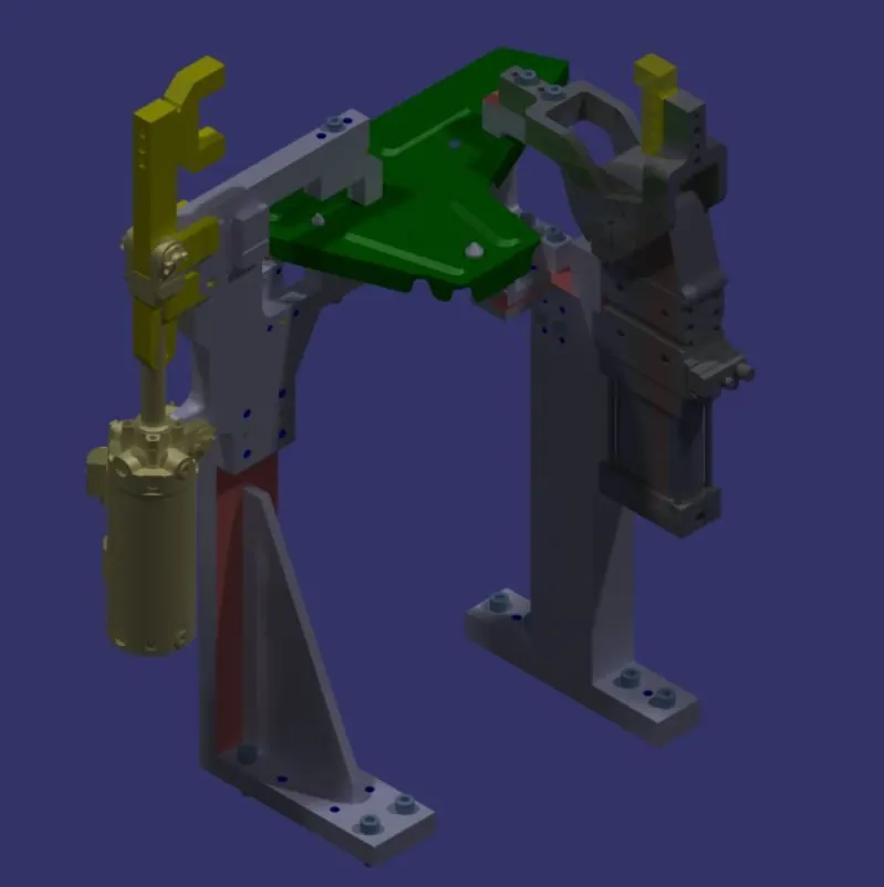
FIG. PIN CLAMP UNITS CONSTRAINING A SMALL PANEL
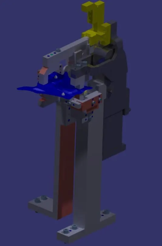
FIG. PIN CLAMP UNITS CONSTRAINING A SMALL PANEL
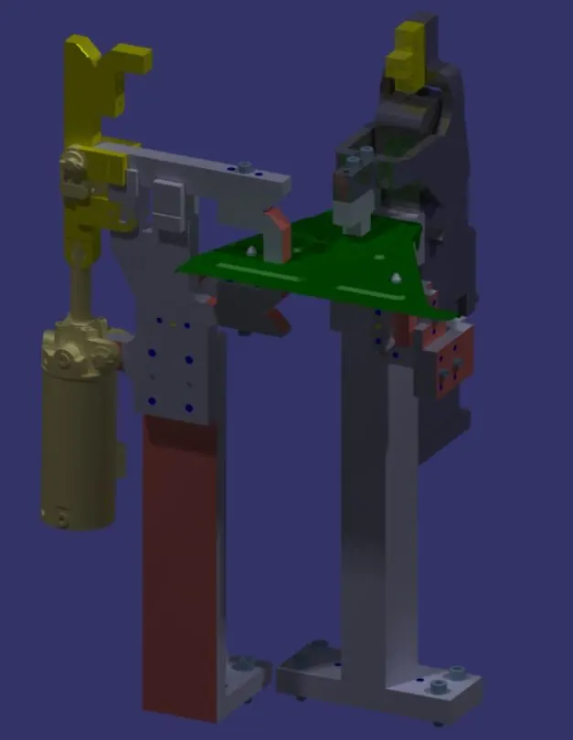
FIG. PIN CLAMP UNITS CONSTRAINING A SMALL PANEL
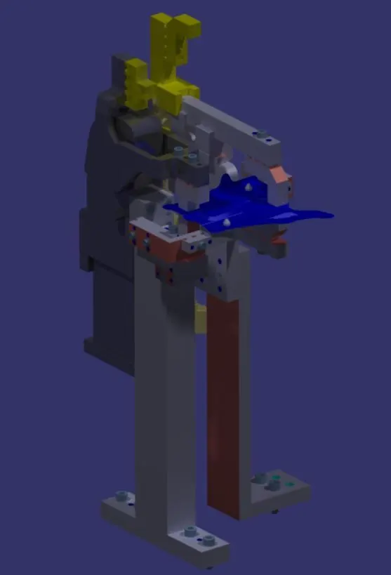
FIG. PIN CLAMP UNITS CONSTRAINING A SMALL PANEL
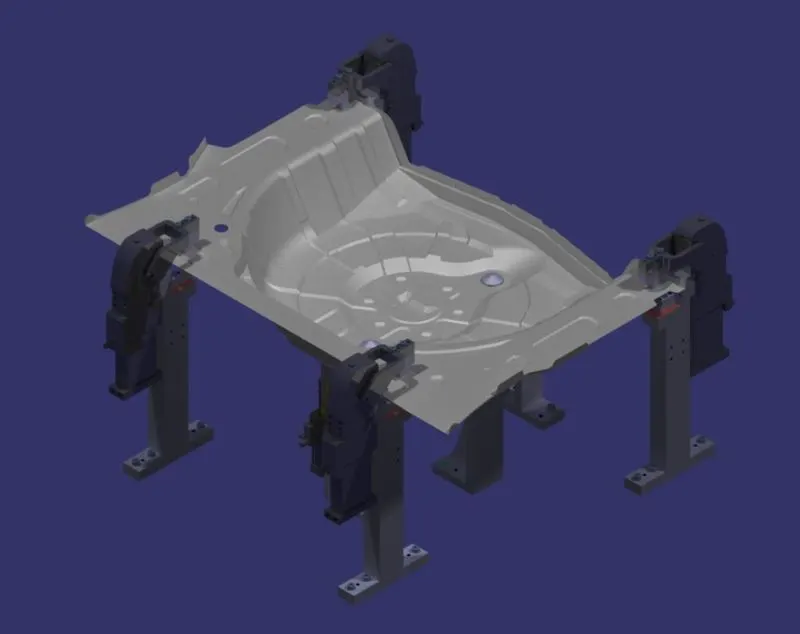
FIG. CONSTRAINING MAIN PANEL
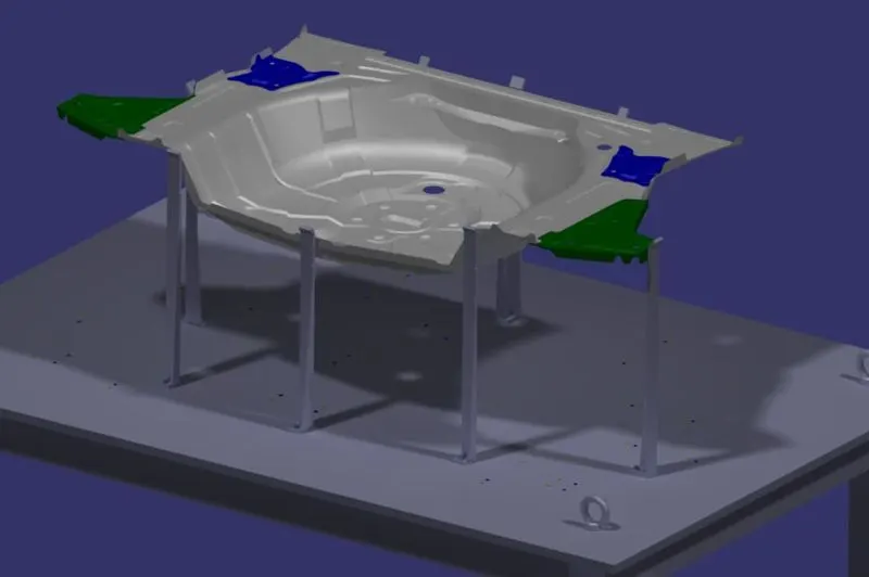
FIG. ROUGH LOCATORS
FIG. FINAL MODEL OF FIXTURE
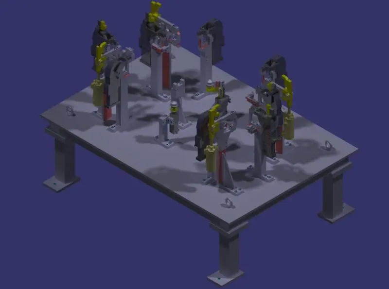
FIG. FINAL MODEL OF FIXTURE
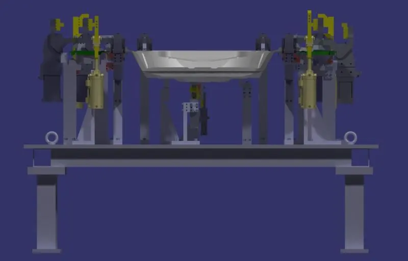
FIG. FINAL MODEL OF FIXTURE
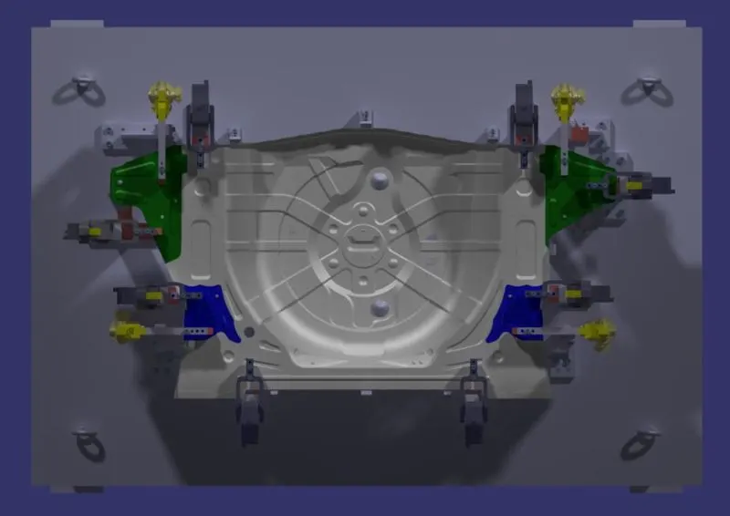
FIG. FINAL MODEL OF FIXTURE