RADIOSS Engine File Editing & 3D Meshing
OBJECTIVE:
- Check the material properties of the rail component and calculate the speed of sound in steel rail
- The length of the rail is about 1000 mm. Calculate the time takes for a shock wave to travel from one end of the rail to the other
- Time for sound to travel the length of the rail
- Edit the engine file so that the stress wave can be monitored moving from one end of the rail to the other during an impact -this will require a termination time equal to the time it takes for the sound to travel the length of the rail (set on/RUN card)
- Set the frequency of animation output to a time that will give 20 animation steps (/ANIM/OT)
- Charge /print -10.
- Mesh the component with tetra mesh while maintaining the size of 5mm and tet collapse 0.15
- Mesh the component with Hexa mesh while maintaining the size of 10mm.
Task-1: Check the material properties of the rail component and calculate the speed of sound in steel rail
We can either check the properties of the component by importing the input files in the Hypermesh Solver, or we can directly check it from the 0000.rad file provided to us. This file can be opened and edited in the notepad as it is in the text format.

After reading the text, we can see that the assigned material to the component is steel with a young’s modulus (E) of 210000 N/mm2 and Density (, RHO) of 0.0078 g/mm3. Using these values, we can find the speed of sound in the steel rail in the following way.
Formula, `sqrt E/rho`
However, before proceeding, we must make all the units in one standard. As density is g/mm3 and Young’s modulus has SI unit, N in its unit, we must convert N in an equivalent unit system.
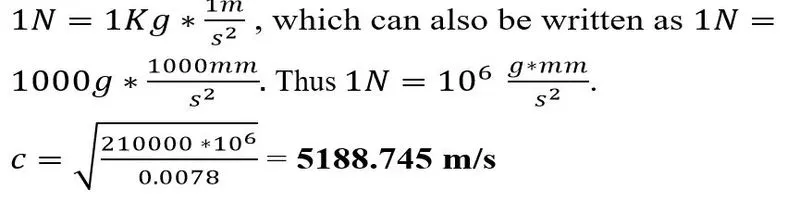
5188.745 m/s
Task-2: The length of the rail is about 1000 mm. Calculate the time takes for a shock wave to travel from one end of the rail to the other.
We know that the shock wave travels with the speed of sound. Thus, we can find the required answer by using the formula.
Given, l =1000mm or 1m
c =5188.745 m/s

0.1927 ms (Second is converted into millisecond)
Task-3: Time for sound to travel the length of the rail.
. Thus , where d=l=1m and s=c=5188.745 m/s.

0.1927 ms (Second is converted into millisecond)
NOTE: For the subsequent tasks, we have to edit the engine file. This can be again done in two ways. We can either edit the 0001.rad file in notepad, or we can edit the values after importing the file in the solver. I am choosing the 1st method to edit the file. We should take care that we are not hampering the standard form of the values. Thus, we should only edit numeric values without touching the entire number form.
Task-4: Edit the engine file so that the stress wave can be monitored moving from one end of the rail to the other during an impact -this will require a termination time equal to the time it takes for the sound to travel the length of the rail (set on/RUN card)
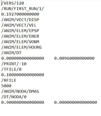
Here, we have to change the runtime in the engine file to the time it takes for the sound to travel the length of the rail, which is 0.1927ms. For this, open the 0001.rad file in note pad and edit the value under /RUN/FIRST_RUN/1/ from 60.0000000000000 to 0.1927000000000.
Task-5: Set the frequency of animation output to a time that will give 20 animation steps (/ANIM/OT)
To get 20 animations, we must do basic math. And, before that, we must understand the current engine file. We, have /RUN/FIRST_RUN/1/ as 60.0000000000000 and /ANIM/DT as 0.000000000000000 1.00000000000000. This means that the animation will run for 60-time steps and animation will be created starting from the 0-time step at every 1-time step. Thus, we will have 60/1=60 animations. Here, we want 20 animations files and we have a runtime of 0.1927ms.
Time= 0.1927/20= 0.0096ms
Now, Change the
/ANIM/DT
0.000000000000000 1.00000000000000
to
/ANIM/DT
0.000000000000000 0.00960000000000
Task-6: Charge /print -10
Simply change the print value to 10 (Which is already set).
Initial engine file:
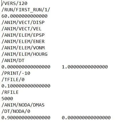
Final engine file:
Task-7: Mesh the component with tetra mesh while maintaining the size of 5mm and tet collapse 0.15.
PROCEDURE:
Method-1: Converting 2D mesh into the 3D mesh.
Step-1: Clean up the surface model. Check for any unwanted free edges and missing surfaces. Later check for the areas where we might face the failure of minimum elements and improve the areas where unnecessary construction lines are present.
Step-2: Mesh the surface model. Go to 2D< Automesh< select the displayed surfaces< choose trias< element length and mesh the surface model.
Step-3: Create a 3D mesh. Once we get a nice quality 2D mesh with no elements failing the minimum and maximum element length criteria, we can go to 3D< tetramesh< elements and choose the 2D mesh elements and hit mesh to get the 3D mesh.
Step-4: Improve the 3D mesh. Go to tools< element check or press F10 to open the element check panel and enter the tet collapse value as 0.15 and check for failed elements. There are two methods to clear tet collapse failure that is explained later.


Method-2: Using quick tetra mesh option
Step-1: Import the model and delete all the solids present in the model. To check if the model has solids please change the option from auto to by Topo, and if the model turns green in color then the model is solid in nature. It is easier to work on the surface model so we must delete a solid model.
Step-2: Clean up the surface model. Check for any unwanted free edges and missing surfaces. Later check for the areas where we might face the failure of minimum elements and improve the areas where unnecessary construction lines are present.
Step-3: Create tetra mesh. Go to view< Browser< Hypermesh< Utility. Select Quick tetra mesh option. Select the component to mesh and set element length value to 3 and choose elements type as trias only. Hit mesh.
Step-4: Improve the 3D mesh. Go to tools< element check or press F10 to open the element check panel and enter the tet collapse value as 0.15 and check for failed elements. There are two methods to clear tet collapse failure that is explained later.
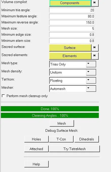
Cleaning Tet collapse elements: As explained earlier, tet collapse failure occur when our 3D elements do not have a proper minimum height. Thus, to resolve this issue we must add height to the failing element. This can be done in two ways:
Way-1:
- Go to Tools< Translate.
- Select the node we want to translate and select the rest three nodes as vectors.
- Translate the node using trial and error values.
Way-2:
- Go to 3D< tetramesh.
- Go to Tetraremesh parameters and set maximum and minimum element length. Also, set the tet collapse value to 0.15 (which is required for this challenge).
- Go to Tetraremesh option< select the elements and hit remesh.


IMAGES OF THE COMPONENT:
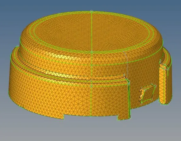
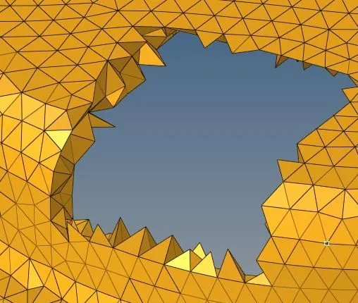
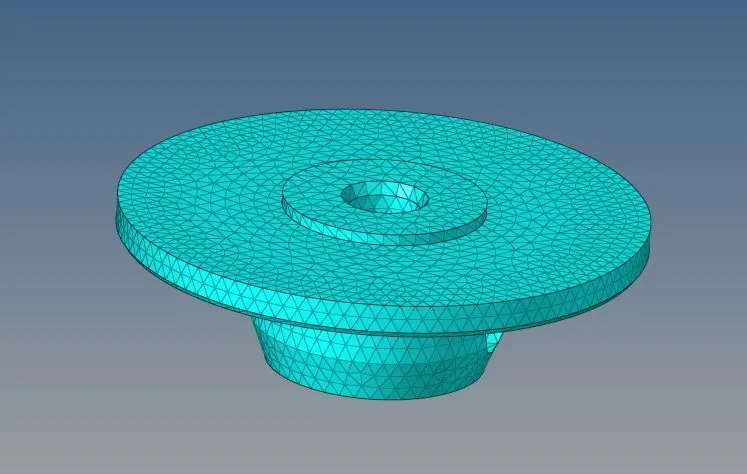
Task-8: Mesh the component with Hexa mesh while maintaining the size of 10mm.
PROCEDURE:
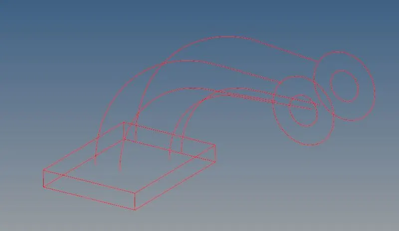
Step-1: Import the model and delete all the solids present in the model. To check if the model has solids please change the option from auto to by Topo, and if the model turns green in color then the model is solid in nature. It is easier to work on the surface model so we must delete a solid model.
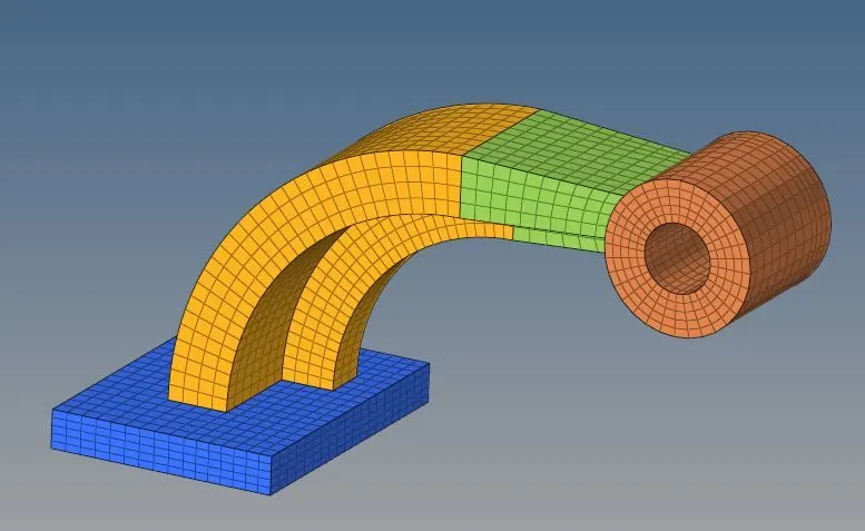
Step-2: Meshing the base. For Hexa mesh, we must have all the quad elements in the model. To get a perfect Hexa mesh, we must create a 2D mesh and convert it into a 3D mesh. Mesh the upper face of the base in 2D with all quad elements. Go to 3D< Solid map. Select elements, select the lines through which we need elements to be dragged, and select element size of density and hit mesh.
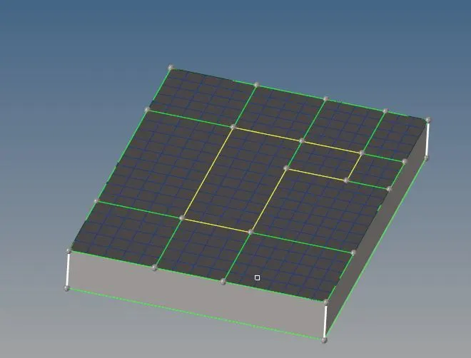

Step-3: Mesh the arm curve. We can again follow the same procedure mentioned above to mesh this part. Alternatively, we can also use the spin command, but it was giving a minute problem on one side so I preferred meshing it using the solid map. One thing we must take care of in this step is the connectivity between the base and the arm curve. We must have exactly equal elements at the surfaces which are in contact.
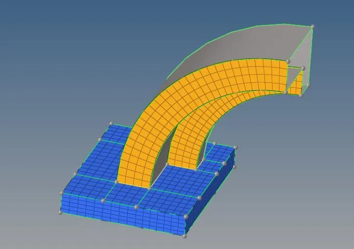

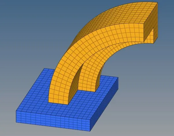
Step-4: Mesh the arm straight. Extract the 2D elements from the 3D elements of the curved arm by going to tools< faces. Mesh the other side of the straight arm with the exact same number of elements that are on the face of the curved arm to get the proper mesh. Use 3D< linear solid option to get a 3D mesh on this part. Make sure that the alignment nodes must be exactly similar on both sides.
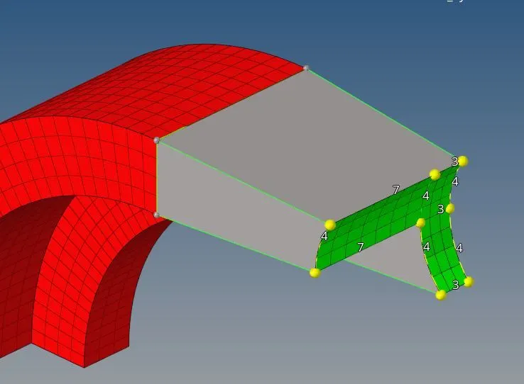

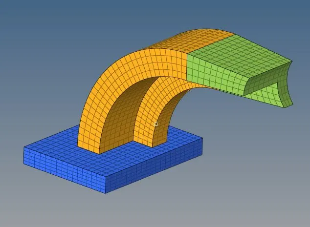
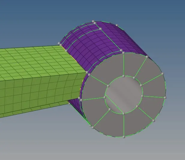
Step-6: Mesh the boss. This component is meshed using the solid map. Create a 2D mesh on the outer circular part of the boss. Again make sure that there is exactly an equal number of elements as on the adjacent component. Use solid map to mesh the component.
FINAL MODEL:
CONCLUSION: Through this challenge, I have learned to read and edit starter and engine files in notepad and in the solver. Further, I have also strengthened my knowledge of tetra and Hexa meshing.