3D Tetra Meshing
OBJECTIVE: Aim of this challenge is to mesh the given components with tetra elements with different methods.
- Method-1: 2D to 3D conversion
- Method-2: Quick tetra mesh
THEORY:
3D Meshing: Meshing is an integral part of the engineering simulation process where complex geometries are discretized into simple geometry. To accomplish that process in HyperMesh we use 1D, 2D, and 3D elements. 3D elements are usually used to mesh volumes. They are derived from 2D elements that are used when the model is more than 6mm thickness. 3D solid elements only account for translational displacements. The three translational unknown displacement functions are u(x,y,z), v(x,y,z), and w(x,y,z). Examples of 3D solid elements are 4-node tetrahedral elements, 10-node tetrahedral elements, 8-node isoparametric elements, etc.
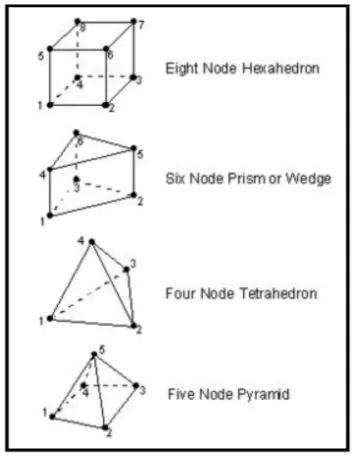
Types of 3D Elements: In general there are four types of 3D elements. They are
- Four node Tetrahedral Elements
- Five node Pyramids
- Six noded Prisms or wedges Elements
- Eight noded Hexahedral Elements
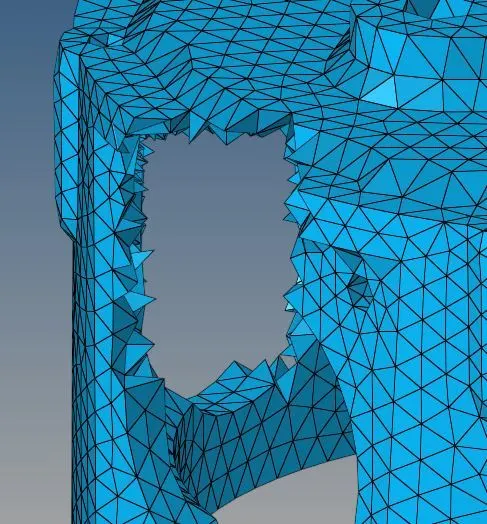
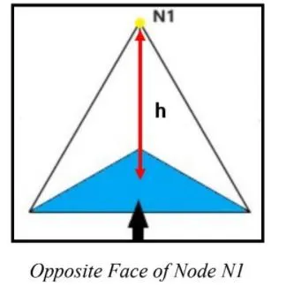
Tet collapse: Tet collapse is one of the quality parameters, which will be checked while generating tetrahedral elements. It can be calculated by measuring the distance of a node from the opposite face, then each of the four values will be divided by the Square root of the opposite face's area. The minimum of four resulting values is then normalized by dividing it by 1.24. Generally, tet collapse can be calculated by the formula = Min of (h/iA) =1.24 Here, 'h' represents the Height, between the Node (N1) and the opposite face of the Triangle. `A' represents the Area of Opposite Face (area of the Triangle).
PROCEDURE:
Method-1: Converting 2D mesh into the 3D mesh.
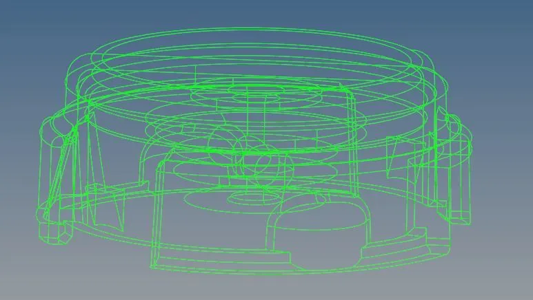
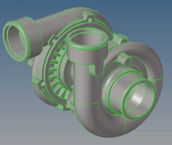
Step-1: Import the model and delete all the solids present in the model. To check if the model has solids please change the option from auto to Topo, and if the model turns green in color then the model is solid in nature. It is easier to work on the surface model so we must delete a solid model.
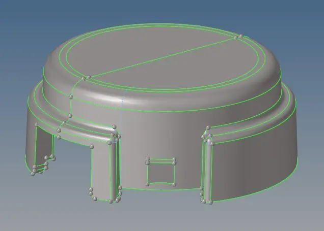
Step-2: Clean up the surface model. Check for any unwanted free edges and missing surfaces. Later check for the areas where we might face the failure of minimum elements and improve the areas where unnecessary construction lines are present.
Step-3: Mesh the surface model. Go to 2D< Automesh< select the displayed surfaces< choose trias< element length and mesh the surface model.
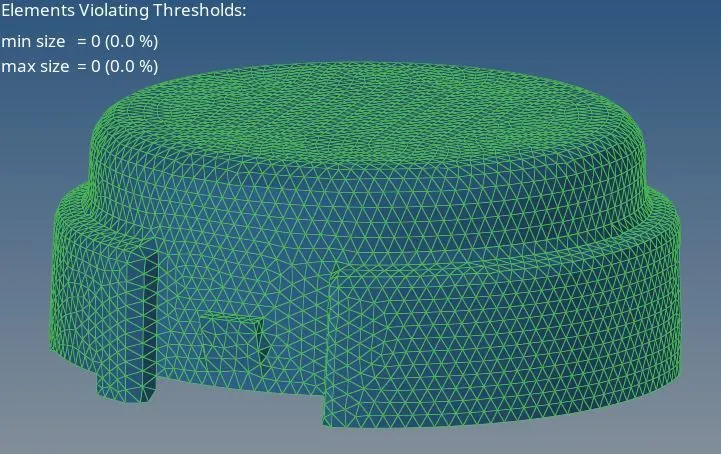
Step-4: Improve the 2D mesh. Go to tools< element check or press F10 to open the element check panel and put the minimum and maximum element length as 3 and 7 respectively. Check for the failed elements and improve them so that they are within limits.
Step-5: Create a 3D mesh. Once we get a nice quality 2D mesh with no elements failing the minimum and maximum element length criteria, we can go to 3D< tetramesh< elements choose the 2D mesh elements, and hit mesh to get the 3D mesh.
Step-6: Improve the 3D mesh. Go to tools< element check or press F10 to open the element check panel enter the tet collapse value as 0.15 and check for failed elements. There are two methods to clear tet collapse failure that is explained later.
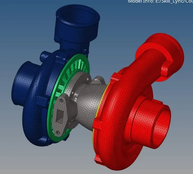
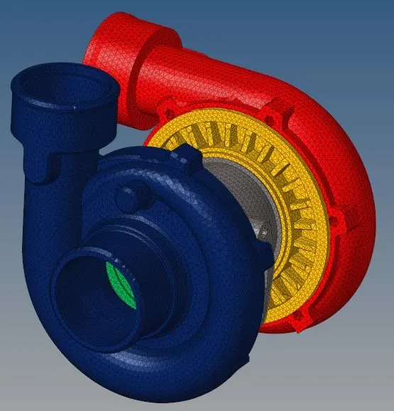
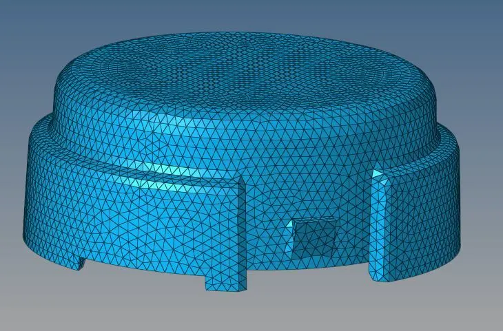
PHOTOS OF MODEL-1 ACCORDING TO THE STEPS:
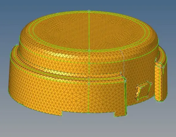
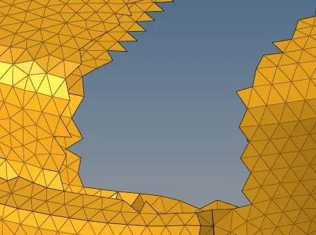
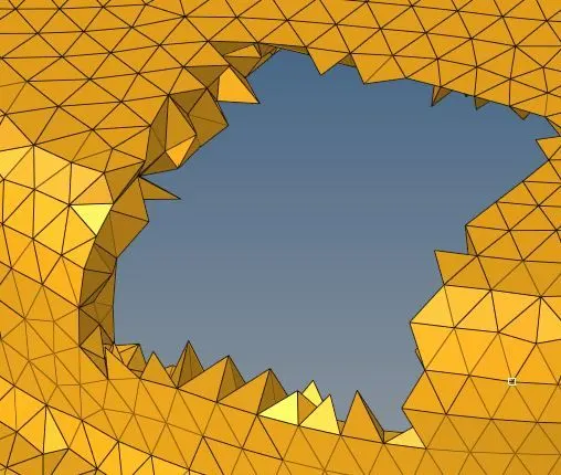
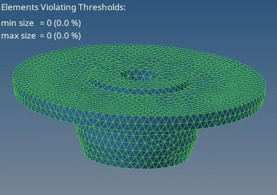
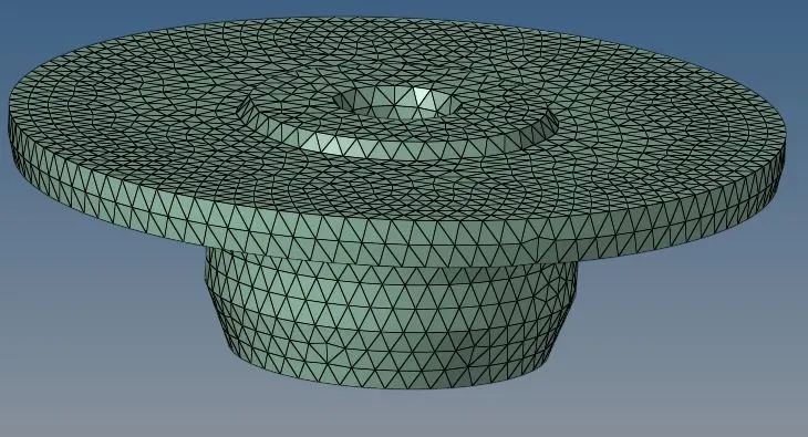
Method-2: Using quick tetra mesh option
Step-1: Import the model and delete all the solids present in the model. To check if the model has solids please change the option from auto to Topo, and if the model turns green in color then the model is solid in nature. It is easier to work on the surface model so we must delete a solid model.
Step-2: Clean up the surface model. Check for any unwanted free edges and missing surfaces. Later check for the areas where we might face the failure of minimum elements and improve the areas where unnecessary construction lines are present.
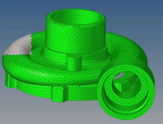
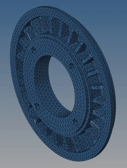
Step-3: Create tetra mesh. Go to view< Browser< Hypermesh< Utility. Select Quick tetra mesh option. Select the component to mesh and set element length value to 3 and choose elements type as trias only. Hit mesh.
Step-4: Improve the 3D mesh. Go to tools< element check or press F10 to open the element check panel enter the tet collapse value as 0.15 and check for failed elements. There are two methods to clear tet collapse failure that is explained later.
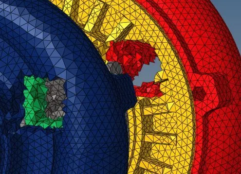
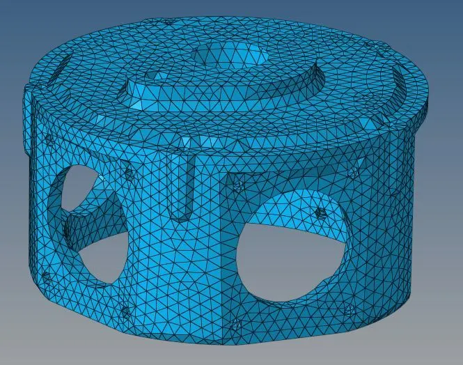
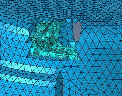
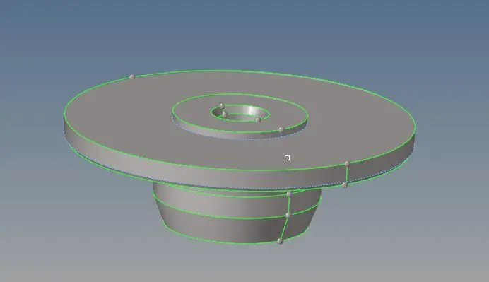
PHOTOS OF MODEL 2 AND MODEL 3 ACCORDING TO THE STEPS MENTIONED ABOVE
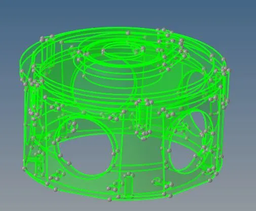
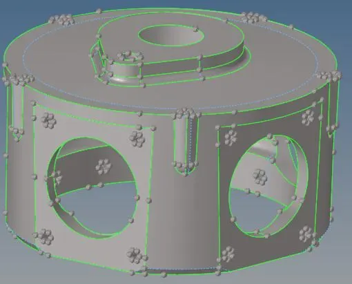
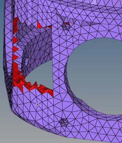
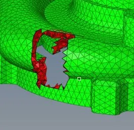
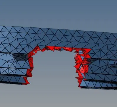
Cleaning Tet collapse elements: As explained earlier, tet collapse failure occur when our 3D elements do not have a proper minimum height. Thus, to resolve this issue we must add height to the failing element. This can be done in two ways:
Way-1:
- Go to Tools< Translate.
- Select the node we want to translate and select the rest three nodes as vectors.
- Translate the node using trial and error values.
Way-2:
- Go to 3D< tetra mesh.
- Go to Tetraremesh parameters and set maximum and minimum element length. Also, set the tet collapse value to 0.15 (which is required for this challenge).
- Go to Tetraremesh option< select the elements and hit remesh.
Once we resolve the issue of tet collapse, we can check it again by going to the element check column and if there are no errors then we can see the following message in the status bar.


CONCLUSION: Through this challenge, I have learned to mesh a component using tetra elements in three ways.
FINAL MODEL: