Design of a Prototype Vehicle for Shell Eco-Marathon
ABSTRACT: Shell Eco-marathon is one of the world’s leading student engineering competitions which brings together science, technology, engineering, and Math students from across the globe to design, build and operate some of the world’s most energy-efficient vehicles. With the growing population, there is a surge in the demand for energy consumption which is increasing the use of fossil fuels like diesel and gasoline. With higher dependencies on such fuel sources, we are emitting tremendous amounts of Co2, Ch4, and N2O into the atmosphere thus speeding up the process of global warming. With the increasing temperature of the earth every form of life and environment is in danger thus demanding the switch of human beings from fossil fuels to cleaner energy sources. The aim of the competition is to challenge students to make the most fuel-efficient vehicle which in turn will emit fewer gases in the atmosphere. Engineering is not only about understanding difficult concepts but also bringing them to practice so they can be used to elevate technology and our society.
1.0 INTRODUCTION:
1.1 COMPETITION BACKGROUND: Shell Eco-marathon is a worldwide energy efficiency competition sponsored by Shell. Participants build automotive vehicles to achieve the highest possible fuel efficiency. There are two vehicle classes within Shell Eco-marathon: Prototype and Urban Concept. There are three energy categories within Shell Eco-marathon: battery-electric, hydrogen fuel cell, and internal combustion engine (gasoline, ethanol, or diesel). Prizes are awarded separately for each vehicle class and energy category. The pinnacle of the competition is the Shell Eco-marathon Drivers' World Championship, where the most energy-efficient Urban Concept vehicles compete in a race with a limited amount of energy.
First of all, teams are required to choose the type of vehicle. As mentioned earlier, it has two categories of vehicles viz prototype and urban concept.
- Prototype: This vehicle type has the potential to push boundaries in energy efficiency. Working within the rules, teams will consider size and weight, and how to make it as streamlined and aerodynamic as possible Prototype: This vehicle type has the potential to push boundaries in energy efficiency. Working within the rules, teams will consider size and weight, and how to make it as streamlined and aerodynamic as possible.
- Urban Concept: Designed for teams to consider city driving, these cars are closer to passenger cars in appearance. They must be built to consider human needs such as driver comfort and space for luggage, and to more road-worth specifications including four wheels and a windscreen wiper. It’s a challenge for teams to create maximum energy efficiency with these added mandatory elements included.
Once the teams choose the type of vehicle they want to build, they are required to choose the category of energy to propel the vehicle. Different energy categories have different competition. Tams have a choice of energy types, engines or motors to power their vehicle reflecting the real-world need for a mosaic of energy options to power transport. The teams will need to innovate new ways to use the least amount of their chosen category. The energy categories are:
Internal combustion engine:
- Gasoline
- Diesel
- Ethanol
Electric vehicle
- Battery electric
- Hydrogen fuel cell
These two are the pre-requisites for the team to commence working on the vehicle. Thus once the team chooses these both they start to work on the design and manufacturing of the vehicle with every analysis, calculations, safety feature etc according to the rulebook. Then it is ready for the competition where the team has to undergo technical inspection and if they are passed then they are allowed to compete with other teams.
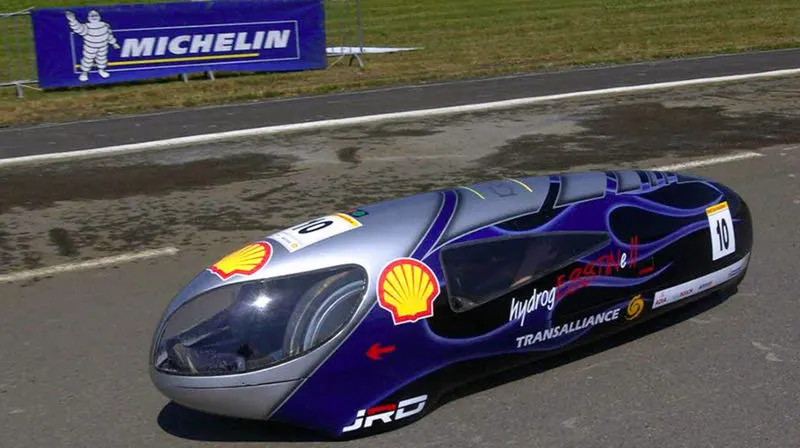
FIG. PROTOTYPE VEHICLE
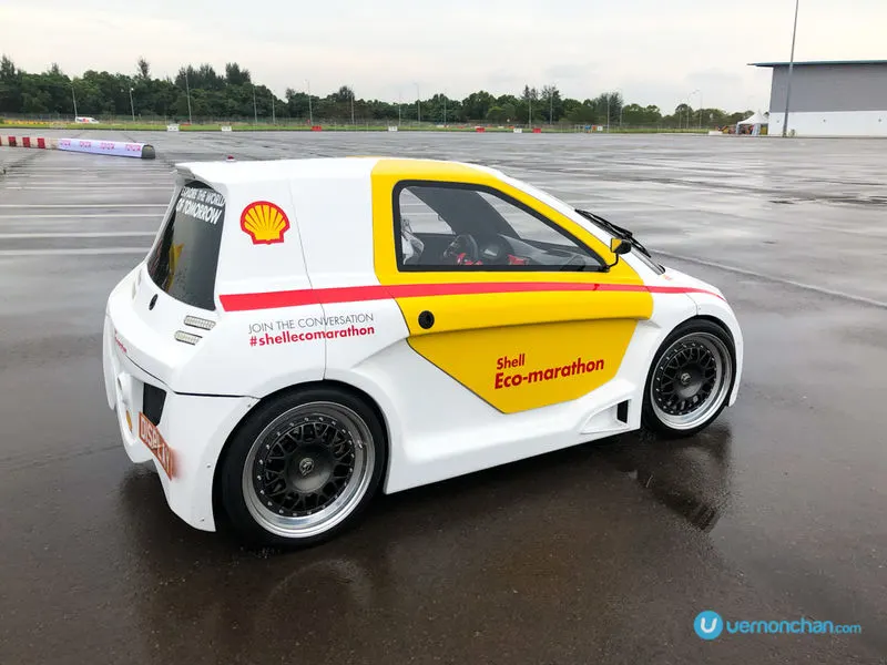
FIG. URBAN CONCEPT VEHICLE
1.2 PROJECT OBJECTIVE AND BACKGROUND: Objective of this project is to design a vehicle for shell eco marathon. I have chosen a prototype vehicle. This project is purely CAD model of the prototype vehicle including frame, steering system and rear wheel assembly and a surface model covering the frame. As the prototype was not designed for any team, the measurements of driver, which otherwise plays a vital role in designing the frame, are not taken into consideration still the measurements are well within the range prescribed by the rule book of shell eco-marathon 2021. To get an entire overview of the measurements, many prototypes of various universities were studied and then chosen to get the vehicle in proper proportion and give it a good look. As this project is solely a CAD representation of the prototype vehicle, attention to other technical aspects like vehicle dynamics, analysis, electric parts are overlooked. Although other aspects, like assigning proper material to ensure the weight of the vehicle is reduced and the vehicle’s efficiency is increased theoretically, designing a proper streamlined body for the prototype to reduce the aerodynamic drag, is corroborated.
1.3 COMPETITION RULES (REQUIRED WHILE DESIGNING A CAD MODEL)
1.3.1 DIMENSIONS
- The vehicle maximum height must be less than 1000 mm.
- The vehicle track width must be at least 500 mm, measured between the midpoints where the tires of the outermost wheels touch the ground.
- The ratio of height divided by track width must be less than 1.25.
- The vehicle wheelbase must be at least 1000 mm.
- The maximum total vehicle width must not exceed 1300 mm.
- The maximum total length must not exceed 3500 mm.
- The maximum vehicle weight, without the Driver, is 140 kg.
- None of the body dimensions above must be achieved by design singularities such as ‘stuck-on’ appendages or cut-outs.
1.3.32 TYRES, WHEELS, AXLES AND WHEEL HUBS
- All types of tires and wheels are allowed.
- Any type of wheel rim may be used. Rims must be compatible with the dimensions of the selected tyres to satisfy safety standards.
- Bicycle wheels are not generally designed to support substantial lateral cornering forces, such as may be found in Shell Eco-marathon vehicles at certain speeds.
- The wheel axles must be designed for cantilever loads (like in wheelchairs) rather than for load distributed equally on both sides (like in bicycles)
- Wheels located inside the vehicle body must be isolated from the Driver by a bulkhead and must not touch the chassis or body.
- Any handling or manipulation of wheels by the Driver is forbidden from the moment the vehicle is at the starting line until it crosses the finish line.
- All installations must be carried out in a way that there is no likelihood the wheels will touch other parts of the vehicle (i.e. cables, wires, hoses, and energy compartment components like batteries, etc.). These must be safely mounted/secured so that they cannot interfere with the turning wheel during driving and cause accidents.
2.0 THEORY
2.1 Design of frame
2.1.1 FRAME: It is the supporting component of automobile vehicle and the foundation for carrying the engine, transmission system & steering system by means of spring, axle, rubber pads etc. The frame is made of box, tubular channels, or U-shaped sections, welded or riveted together.
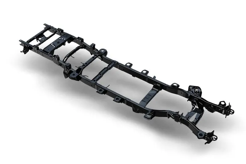
FIG. FRAME
2.1.2 CHASSIS: When engine, transmission system, steering system & wheels are fitted on the frame, the assembly known as the “chassis”. It is the backbone of the vehicle. It is basically the vehicle without a body. It contains all the major units necessary to propel the vehicle.
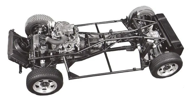
FIG. CHASSIS
2.1.3 Types of automobile chassis considered for the prototype: Even if the analysis is not the part of this project, I have researched on the type of loading condition and how will it impact the frame and the vehicle in general. Mostly the list narrowed down to three types of automobile chassis considering the weight of the vehicle for the competition viz Ladder frame, monocoque and space frame. After comparing them, it was decided to choose spaceframe chassis like used in many prototypes and other events.
2.1.3.1 Ladder frame: The most basic chassis structure is the ladder frame design, named after its resemblance to a conventional ladder (Waterman, 2011). This structure is built from two members that run parallel through the length of the vehicle, connected by multiple members perpendicular to the chassis direction. In the early days of motorcar production, the construction method was basically a body bolted onto the ladder frame on which the engine, drive train, and suspension are all mounted. It was then the best way to produce a car based on existing technology and machinery. Currently, almost all commercial and some off-road vehicles are constructed in this manner. With vans, trucks, and buses, the body-on-frame method offers the flexibility to bolt on different body styles. The ladder chassis, however, is not used in most passenger car production today because the ladder has to be made strong enough to take all the suspension load and, at the same time, support the body and mechanical components. This results in a frame that is far heavier than an equivalent unitary body construction where the chassis and body are basically one. Also, the ladder frame lacks the structural stiffness for good dynamic characteristics at speed.
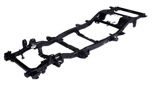
FIG. LADDER FRAME
2.1.3.2 Monocoque: A monocoque chassis design carries the potential for a stiffer and stronger chassis structure. It makes use of plates and shells loaded in shear to construct a closed box that acts as a protective outer body work with a rigid internal structure that is able to carry all loads. The benefit of using entire panels and shells is a higher polar moment of inertia in the longitudinal direction. This reduces torsional stresses which promote better handling and a safer design. With a high material consumption, special material composites are often used to reduce the compromise on weight. Carbon fiber composites have recently been introduced as a means of enabling a lightweight, smooth yet strong structure. The manufacturing process for carbon fiber composites is complex.
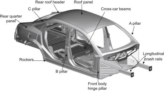
FIG. MONOCOQUE FRAME
2.1.3.2 Spaceframe: A Spaceframe Chassis is an assortment of interlocking struts and braces arranged in triangular or pyramid-like patterns to make a complete frame. It usually distributes its weight evenly in all directions and is strong but lightweight compared to a similar-sized self-supporting structure which improves performance in a vehicle. They have been used in the construction industry but the technology have been used in the automotive industry as car chassis as early as the 1930's.
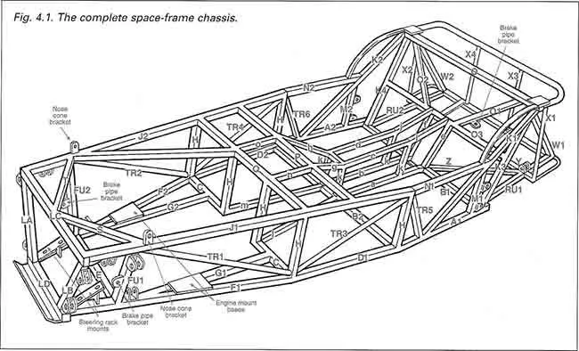
FIG. SPACEFRAME
2.1.4 Material and cross-section selection
2.1.4.1 Material selection: Most commonly when we talk about the material selection we would strike with steel and aluminum at our first thought. They both have their advantages and disadvantages. Moreover, with various grades available in market, it would require a thorough study to choose amongst them. The purpose of the competition is to make a fuel-efficient vehicle and aluminum is lighter and has less density than steel, which makes aluminum a better choice over steel even if it is expensive than the latter. Aluminum might win against steel when compared to its weight and density but it will clearly lose against carbon fiber in the same aspects. Again, carbon fiber is not just a material that is as uniform as metals. The former can be tweaked to get better properties than metals. It is not easy to compare the properties of carbon fiber against steel or aluminum. Unlike carbon fiber, metals are usually uniform– isotropic, which ensures the same properties in every direction. The strength and rigidity of a carbon fiber component are created by positioning fabrics in a specific way.
Carbon fiber is a material that offers stiffness and strength at low density– which is lighter than aluminum and steel that provides many practical benefits. Carbon fiber offers 2 to 5 times more rigidity (depending on the fiber used) than aluminum and steel. In the case of specific components that will be stressed only along one plane, made from one-direction carbon fiber, its stiffness will be 5-10 times more than steel or aluminum (of the same weight). And this is one of the advantages of carbon fiber over steel and aluminum. The link http://www.dexcraft.com/articles/carbon-fiber-composites/aluminium-vs-carbon-fiber-comparison-of-materials/ has a detailed blog on it. So to conclude carbon fiber can be used to reduce the weight further without compromising on strength and rigidity but this will be very expensive. In this project, I was not under the obligation to design within a budget as I only have to apply the material. So I went for carbon fiber as it looks cool too.
2.1.4.2 Cross-section selection: A cross-section of the tube used also plays an important role in deciding the weight of the frame and consequently, the entire vehicle. Simple math can be done to prove this point. I had to choose between circular and thin-walled cross-sections. Let us assume a circular cross-section with a 10mm radius and 1mm thickness and a thin-walled cross-section with 20mm length and width and 1mm thickness of the same material. We have to determine the weight of both of them and select a cross-section.
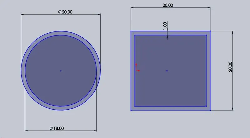
FIG. CROSS SECTION
This means as they are made of the same material, they must have the same density. And let us assume the unit length of the cross-section. That would mean our volume can be narrowed down to Area as volume=area*length. Thus our equation now becomes Mass= area.
Area (circular c/s)= that is area( circular c/s)= 59.66 sq mm
Area (thin-walled box)= that is area (Thin-walled box)= 76 sq mm
Thus, the weight of a circular cross-section is less than a thin-walled cross-section. So it would be logical to select the circular cross-section for the frame.
2.2 Steering System
2.2.1 Steering system: The Steering system converts the rotation of the steering wheel into a swiveling movement of the road wheels in such a way that the steering-wheel rim turns a long way to move the road wheels a short way. The steering effort passes to the wheels through a system of pivoted joints. These are designed to allow the wheels to move up and down with the suspension without changing the steering angle.
2.2.2 Types of steering system considered for prototype: Almost at the start of the project I have decided to design a steering system identical to that of the go-kart. Even though I studied 3 various systems which are as follows:
2.2.2.1 Rack and pinion system: Rack and pinion steering uses a gear-set to convert the circular motion of the steering wheel into the linear motion required to turn the wheels. It also provides a gear reduction, so turning the wheels is easier. It works by enclosing the rack and pinion gear-set in a metal tube, with each end of the rack sticking out from the tube and connected to an axial rod. The pinion gear is attached to the steering shaft so that when the steering wheel is turned; the gear spins, moving the rack. The axial rod at each end of the rack connects to the tie rod end, which is attached to the spindle. It provides a greater choice for steering ratio as only the pinion gear would need to be replaced. However, it is sensitive to misalignment and can be unreliable and it is also heavier than other options due to the increased number of metal components
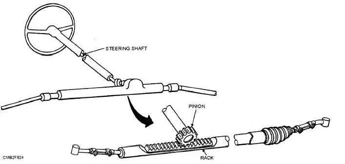
FIG. RACK AND PINION STEERING SYSTEM
2.2.2.2 Tie rods on the steering column: It consists of connecting the tie-rods from the wheel hubs directly to the steering column (or through the use of a Pitman's arm – a lever that extends from the steering column which is rigidly connected to the column). It is lighter than other options due to the smaller number of metal components. It is also more reliable as it is a pin-jointed mechanism, which is less sensitive to misalignment. However, the wheel angle may not change linearly with the steering input angle – depending on the geometry of the Pitman's arm.
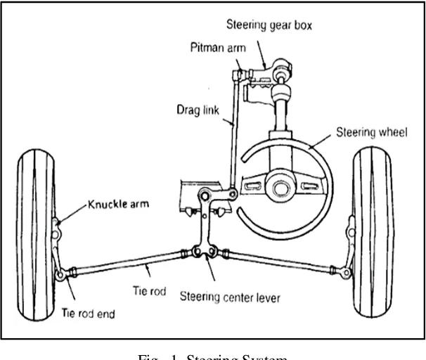
FIG. TIE ROD STEERING SYSTEM
2.2.3 Components of steering system: For this project, a tie rod steering system is designed. The actuation method from the steering column to the tie rod was also considered. Two methods were taken into consideration. First was more reliable and commonly used in the passenger cars that are the use of the universal joint. A universal joint was designed to transfer the motion from steering column through two pillow block bearings to the pitman’s arm but due to complexity, the design failed again and again so I resorted to a simple method of actuation which can be found on student’s go-kart. This method included to simply mount a bearing at an angle to make steering column stable and to actuate the motion directly to the pitman’s arm. So the steering system consisted of the following components:
- Steering column
- Pitman’s arm
- Tie rod assembly
- Mounting plate with brackets to mount tie rods
- Axel to mount front wheel
2.2.4 Mounting steering system on frame: As the frame is made from circular tubes, it was not possible to mount the steering system like that on a go-kart. But, a similar design was inspired by the go-kart and other prototypes. The collars are used to mount on the circular frame and mounting plates are fastened to it from both sides. These mounting plates are fastened to the bracket on the other side. The brackets are joined to the steering mounting plate with the eye bolt. And a stud is relatively fixed to the bracket. Thus this arrangement only allows the mounting plate to rotate about the axis of the stud. When we would rotate the steering we would get the motion of the wheels.
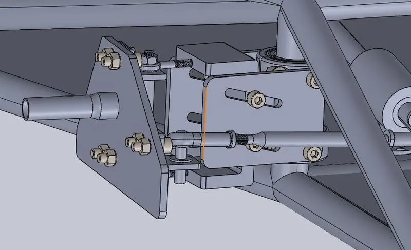
FIG. MOUNTING STEERING ON FRAME
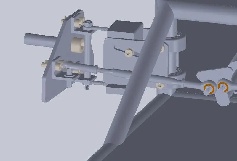
FIG. MOUNTING STEERING ON FRAME
2.3 Transmission system
2.3.1 Introduction to transmission system: A car transmission is one of the most important components of a vehicle. It’s what moves the power from the engine to the wheels. There are a variety of car transmissions. Some are automatic, while manual transmissions in stick-shift cars require the driver to complete extra steps for the vehicle to operate effectively. The working of transmission varies depending on the type of transmission. Whatever type of transmission it is, the answer to what does a transmission does is to enable the gear ratio between the drive wheels and engine to adjust as the car slows down and speeds up. When a vehicle is stopped, the transmission disconnects the engine from the drive wheels so that the engine can keep idling when the wheels aren’t in motion. Transmissions also enable quick acceleration from a stop and enable the engine to run more slowly to cut down on wear while the vehicle is driving at consistent speeds.
2.3.2 Transmission system proposed for the project: From the given sources of power I chose electric to power the prototype. Thus following components come under the transmission system proposed for the vehicle:
- Accelerator pedal to control the speed
- Controller
- Battery
- Joulemeter
- Motor
2.3.3 Motor selection: Two types of motor are available, based on their power sources, to choose from. AC motors are chosen for high efficiency and constant torque while DC motors are chosen for high starting torque which is desired for EV. DC motors provides 1.2-1.4 times the starting torque of AC motors. Let us look at their types to be sure which motor should we choose.
|
AC MOTORS |
DC MOTORS |
|
Permanent magnet 3 Phase AC induction motor 1. High efficiency 2. Compact and lightweight 3. Not available readily in Indian markets |
Brushed DC motors 1. High maintenance 2. Low efficiency 3. Higher weight and size 4. Readily available in the Indian market 5. Was widely used but faded with time. |
|
Brushless DC motors 1. Moderate efficiency 2. Moderate size and weight 3. Higher efficiency than brushed motors 4. Popular in the Indian market 5. Readily available in markets. |
|
|
Permanent magnate brushless DC motors 1. More efficient than both 2. Durable and compact size 3. Better performance 4. Expensive than others 5. Availability is subjective. |
Thus from the chart above our direct choice would be a permanent magnate BLDC motor only if we don’t have to worry about the pocket. But money is a constraint then brushless DC motor is an ideal choice due to its availability, efficiency and cost. So I recommend BLDC motor.
2.3.4 Transmission of power to prototype: As we talked about the transmission system, we must talk about the method of transmitting the power from the motor to the rear wheel. In commercial cars we come across transmission shaft doing this work and in bikes a chain drive. For this prototype I have simply designed a chain drive to transmit the power from motor to the rear-drive. Chain drive runs between the sprocket on the motor and the free wheel on the rear wheel thus connecting both and transmitting the power.
Gear ratio: It is defined as the ratio of the number of rotations of a driver gear to the number of rotations of a driven gear.
No of teeth on freewheel= 18 (driven)
No of teeth on sprocket= 9 (driving)
G= 18/9 i.e. G=2.
This 2 implies that driving gear has to rotate 2 times to rotate the driven gear for 1 time. Torque output is twice and speed output is ½.
2.3.5 Motor calculation: Once the type of motor is selected, we have another dilemma of choosing the right motor. If we choose any rating motor directly, there will be consequences like the motor is suitable for the prototype and not delivering enough power or we end up choosing a higher rating motor which is delivering power but came at a greater cost which can easily be reduced by choosing a motor with meticulous calculations. As all I can do for this project is theoretical calculations, many of the values are assumed by making an educated guess and from other sources by comparing with their prototype.
2.3.5.1 RPM at wheels: A general assumption I made here is with respect to top speed of the vehicle. Usually, in the competition the vehicles have a speed of 15-20 KMPH which is very less, I assumed the maximum speed that I want to achieve to be 20KMPH. But to compare the results I also am doing the calculation assuming the max speed to be 40KMPH which is bizarre as this is not a racing event but efficiency event and both are inversely proportional in general. Also because the motor requirement for 40kmph will be of greater rating, this would mean more money and overall weight.
- Wheel diameter = 17’’= 0.43m
- Circumference= D= *0.43= 1.35m (That means my wheel travels 1.35m in 1 rotation)
- Speed1 (required)= 20KMPH= 5.55m/s; Speed2 (comparison)= 40KMPH= 11.11m/s
- RPM1 (for 20kmph)=55*60/1.35= 247RPM
- RPM2 (for 40kmph)= 11*60/1.35= 495RPM
Values required for further calculations:
- For 20kmph: Speed (v) = 5.55m/s and RPM1= 247RPM
- For 40kmph: Speed (v) = 11.11m/s and RPM2= 495 RPM
2.3.5.2 Power and torque from vehicle: This formula contains a few values which must either be calculated practically or through analysis. Due to the lack of both, I opted to assume the values more than other prototypes.
- Dimensions of the vehicle: Ht= 660mm Width= 600mm length= 2710mm
- Mass of the vehicle: with driver’s wt+ other components weight+ chassis wt= 150kg (assumption)
- Coefficient of drag: as the body of the car is pretty much streamlined and others have achieved drag as low as 0.07 I am assuming it to be 0.15
- Rolling resistance: 0.02
Power= (m*g*v*rolling resistance) + (air density* coefficient of drag* area* v^3) + (m*g*sin10*v)
After inserting all the values we get
For 20kmph
Power= 1557.575 W
Torque= P*60/ (2*pi*N) where N is 247 RPM
Torque= 60.22 Nm.
For 40kmph
Power=3158.413 W
Torque= 61Nm
As torque for both 20kmph and 40kmp is nearly equal we will thus assume it to be same to draw general logical inference further.
2.3.5.3 Motor calculation: In the market, motors are available in standard ratings. We will use this rating to calculate if the chosen motor is giving us the required power. We will compare 2 motors available in the market viz 500 watts 2750 rpm and 1000watt 3000rpm.
- 500 W and 2750RPM
- Torque of motor= 500*60/(2*pi*2750)= 1.74 NM
- Torque required= Torque of vehicle/gear ratio= 60/2= 30NM
- Gear ratio= torque required/torque of motor= 30/1.74= 17.2:1
- RPM at new G= 2750/17.2= 159.88 RPM
The calculation for both the speeds i.e. 20kmph and 40kmph can be taken as same due to nearly same torque. Thus we can directly infer that t 20KMPH we need 247RPM and at 40KMPH we need 495RPM. This is motor is delivering 159.88 or 160RPM which is way below the required values so this motor fails to fulfill our purpose . Also, we can easily infer from this calculation alone that 40KMPH would require a motor way above the ratings of 20KMPH.
- 1000W and 3000RPM
- Torque of motor= 1000*60/(2*pi*3000)= 3.18 NM
- Torque required= Torque of vehicle/gear ratio= 60/2= 30NM
- Gear ratio= torque required/torque of motor= 30/3.18= 9.5:1
- RPM at new G= 3000/9.5:1= 315.79 RPM
This motor is selected as it is delivering the 315RPM and our requirement is 247RPM. Also if there are any errors in assumptions, they can be nullified with this motor as it is giving more than enough power.
2.3.6 Tires selection: As mentioned numerous times, the motive of the competition is fuel efficiency and tires do play a vital role in this. In general they do play a role in how efficiently your car performs, depending on how well they are maintained and the size of your wheel. Let us look in brief what impact wheel has on fuel efficiency.
- Tires size and fuel efficiency: The size of the wheels plays an important role in fuel efficiency. Larger tires decrease your fuel economy because they are heavier, while smaller tires increase fuel efficiency. Bigger tires also have a higher rolling resistance than smaller tires which means they require more resistance and effort to get them rolling. However, if you do a lot of freeway driving at high speeds, having larger tires can help increase your vehicle’s fuel efficiency.
- Air pressure and fuel efficiency: Another thing that can affect the fuel economy of your car is the air pressure in your tires. If the air pressure in your tires is low, it provides more resistance, causing your car to expend more effort to get going. Luckily, this problem is well within your control to fix. If you check the air pressure in your tires regularly, you can ensure that you maintain the recommended psi for optimum performance.
- Tire treads and fuel efficiency: Tire treads can also impact your fuel economy. There’s a reason that race car drivers use tires with no tread. They provide less resistance and allow their vehicles to more easily ascend to higher speeds. Unlike race car drivers, however, we need to tread on our vehicles to help our cars easily brake when the weather is bad. If you are using chunky tires that are suited for off-roading, but you don’t regularly drive off-road, you may be significantly decreasing your fuel efficiency. The solution is to purchase street tires for your vehicle so that your car doesn’t do as much work.
- Wheel material and fuel efficiency: If your tires are small, have good tread, and you check your air pressure regularly, but you still think your vehicle could be more fuel-efficient; you can customize your wheels. Most wheels are made of steel, but depending on the weight of your vehicle, you may be able to opt for a light alloy wheel. This could decrease the weight of your vehicle and, thus, minimize your car’s resistance. However, be aware that this may affect the types of tires you can buy for your car. If it forces you to get wider tires, you will be trading off some fuel efficiency.
2.3.6.1 Tire selection for the prototype: In the CAD model I have designed the tires just for representation purpose but if I were to suggest the tires without taking cost or availability into consideration, I would point towards Michelin Ultra-low resistance tires which are developed especially for shell eco marathon competition. These tires use up to 6 times less energy than the most fuel-efficient tire in the market. This must be a perfect pick without any doubt. The link is to the video of Michelin explaining about this tire: https://www.youtube.com/watch?v=1YyrNRfeInI. They even have explained the technicalities of the tires in a separate blog. This surely would attract anyone to buy their tires https://thetiredigest.michelin.com/michelin-ultimate-energy-tire.
2.3.7 Braking system: A brake is a mechanical device designed to restrain motion by absorbing energy from a moving system usually by the means of friction. It is used to slow or stop a moving vehicle, wheels, axle, etc. The braking system is a complicated device with a lot of parts, but its working seems very easy. After all, pressing a single pedal will activate all brakes on the four wheels. The slowing down is achieved by hydraulic fluid, which is often bled to get the best performance of the breaking. Air is not allowed in the system else the component won’t work well.
Most brakes are designed to use friction between two surfaces; they’re pressed to convert the kinetic energy of the moving object into heat. Though several methods of energy conversion are now employed. In an automobile, friction brakes store braking heat in the drum brake or disc brake which then gradually converts into the air.
In modern vehicles, the brake pedal is pushed against the master cylinder. There is a piston that pushes the brake pad against the brake disc, which slows the wheel down. On the brake drum, the cylinder pushes the brake shoes against the drum to slow down the wheel.
2.3.7.2 Components of the braking system: Due to complexities and lack of dimensions a few components cannot be represented properly or are not represented at all. But these components will be standard or directly purchased from the market to be mounted on the vehicle. The braking system of the prototype will have the following components:
- Brake lever
- Hydraulic cylinder
- Hydraulic lines
- Disc brakes
- Calipers
2.3.7.3 Braking system in prototype: The competition rules make it mandatory for the teams to incorporate two individual, hydraulically operated brakes for front and rear wheels. So to fulfill this requirement every team has to provide two brake levers, one of which is for the rear-wheel alone and another is for both the front wheels. When front brake is applied, it forces the fluid to travel to master cylinder which enlarges and diverts the pressure to both the calipers mounted on the disks of the front wheels and hence the speed can be reduced. Similar operation is for rear wheel.
3.0 DESIGN PROCEDURE
3.1 Design of frame: As mentioned earlier, the dimensions were assumed from the chassis of existing prototypes. The shape of the spaceframe was inspired by a go-kart and a prototype. First a frame like a go-kart was designed and later the members were added on the sides and edges of the frame to make it spaceframe. This frame is designed in CATIA generative shape and part workbench. The procedure followed to design the frame can be summed up as follows:
Base sketch followed by adjacent sketches were created. This is basically the backbone of the design as everything that will be made further will have this as reference. This sketch can be assumed as the line representation of the frame.
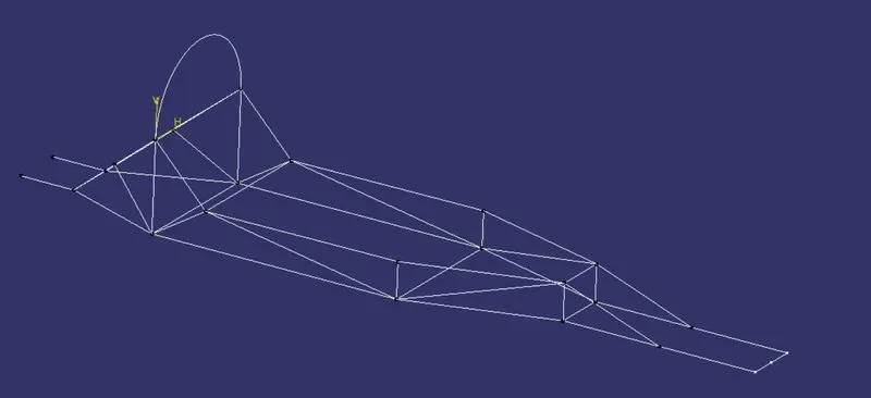
FIG. SKETCH FOR FRAME
After the sketch was created, surfaces were made resembling the circular tubes of radius 10mm. This was done using sweep command. And to ease this process, many lines and sketches were joined together to sweep in one single command.

FIG. TUBES AROUND THE SKETCH
Once the tubes were created, the job was half done as the joints must be edited. As many tubes ended at a single joint, they must be made a single joined by pruning the extensions of the other joints beyond some other joint. So at joints, the split command was used to remove the unnecessary part of the tubes and make it into one single joint.
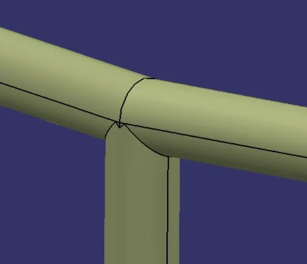
FIG. EDITING JOINTS OF THE FRAME
Final step to create the frame was to convert the surfaces into solid bodies. This was done using thicken command in the part workbench. All the tubes are thickened inside by 1mm. Once this process was finished, the frame was assigned carbon fiber material.
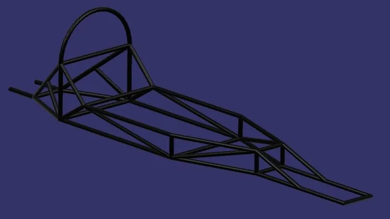
FIG. MAKING SOLID TUBES
In addition, a sheet was also created in the same model. Sheet will act as protective guard between ground and driver. Basically, this will be the floor of the prototype. This was also assigned carbon fiber material.
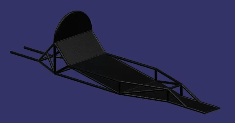
FIG. CREATING FLOOR SHEET
3.2 Design of steering system: This design is an assembly of relatively simple components like steering column, pitman’s arm, ties rod assembly, mounting plate, etc. Many of these components are easy to design so only their photos will be shown rather than an entire description of the process.
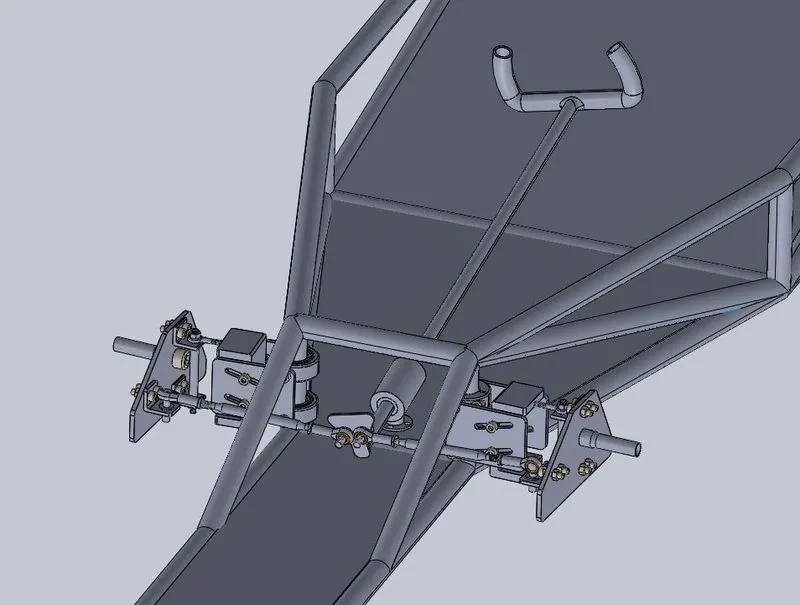
FIG. STEERING SYSTEM
3.2.1 Steering column and pitman’s arm: made as a single unit to reduce the number of individual components. A simple procedure is required to design this component.
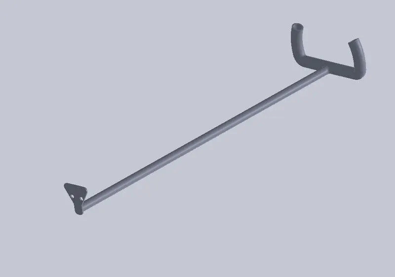
FIG. STEERING COLUMN
3.2.2 Tie rod assembly: This assembly consists of eye end, tie rod, ball, and ball cavity.
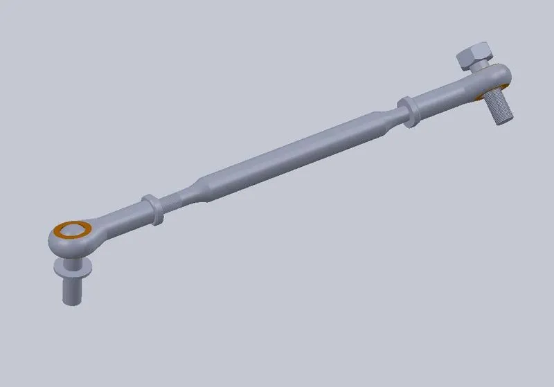
FIG. TIE ROD ASSEMBLY
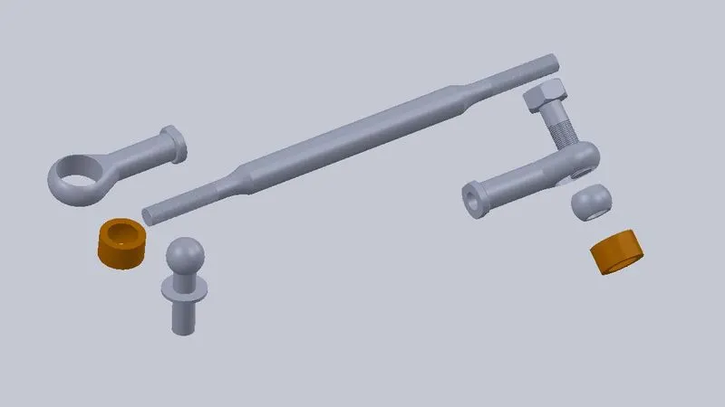
FIG. TIE ROD ASSEMBLY EXPLODED VIEW
3.2.3 Brackets: Designed to mount the various components.
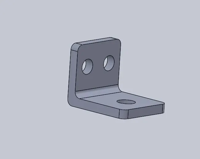
FIG. BRACKET FOR MOUNTING PLATE
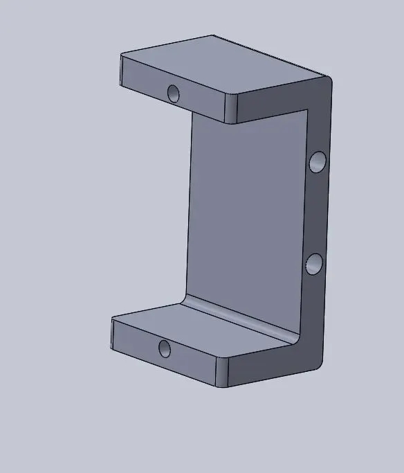
FIG. BRACKET FOR MOUNTING EYE BOLT AND CONNECTING PLATE
3.2.4 Mounting plate: A main mounting plate is the one where other components like small brackets, cylindrical way for stud, axel are mounted. This plate mounts tie rods and front wheel too.
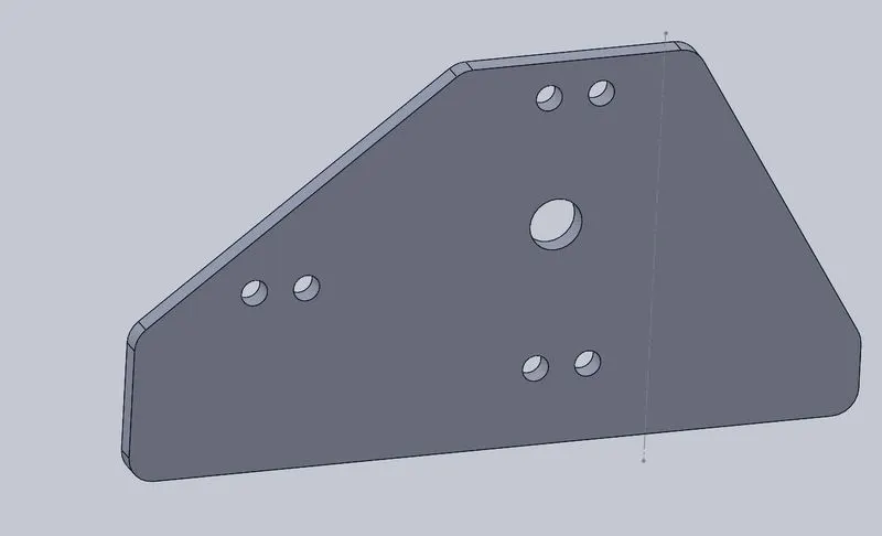
FIG. MOUNTNG PLATE
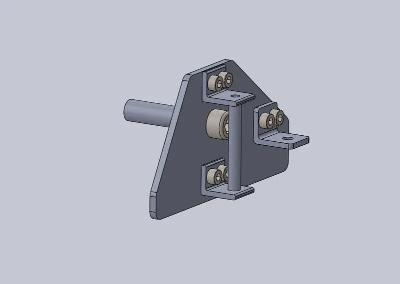
FIG. MOUNTED AXEL, BRACKETS AND CYLINDRICAL CAVITY FOR STUD
3.2.5 Connecting Plate: This plate connects mounting collars and brackets.
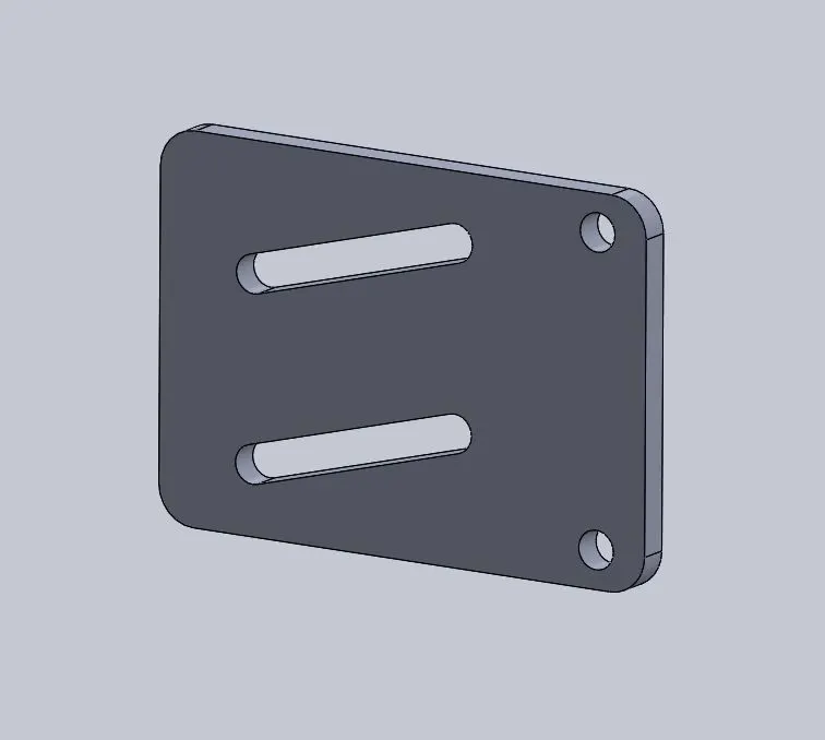
FIG. CONNECTING PLATE
3.2.6 Eye bolts: To fix the stud to the bracket that is to the frame.
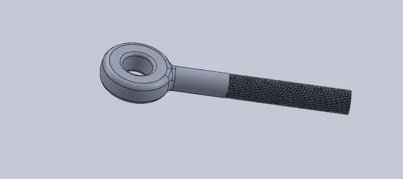
FIG. EYE BOLT
FIG. MOUNTED STEERING SYSTEM.
3.3 Design of front and rear wheels: The design of both the wheels is same with a minor difference. Rear-wheel has to mount a free wheel on it and front wheel does not. Apart from this the entire design of both the wheels is same, so same file is used and renamed to design rear wheel. Also, both wheels are an assembly of many components like axel, hub, nuts, ball bearings, etc.
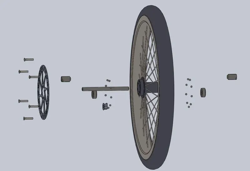
FIG. EXPLODED VIEW OF ASSEMBLY OF WHEEL
3.3.1 Design of Front wheel
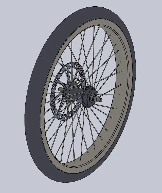
FIG. ASSEMBLY OF FRONT WHEEL
3.3.2 Design of Rear-wheel
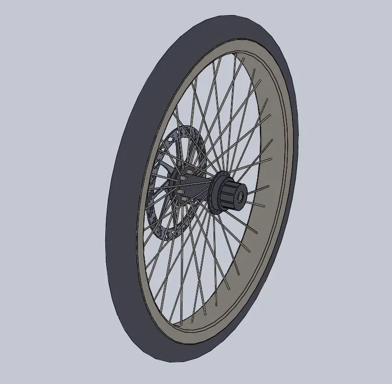
FIG. ASSEMBLY OF REAR WHEEL
3.4 Design of chain drive: The method of actuation of power from battery to the rear wheel is done through a chain drive. This is a tricky assembly, so after all the proper dimensions and design of freewheel, sprocket, and chain links, and then it was assembled in the main assembly.
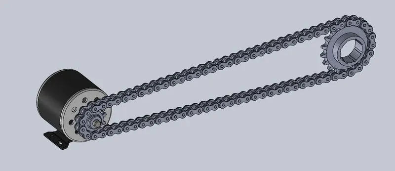
FIG. ASSEMBLY OF CHAIN DRIVE
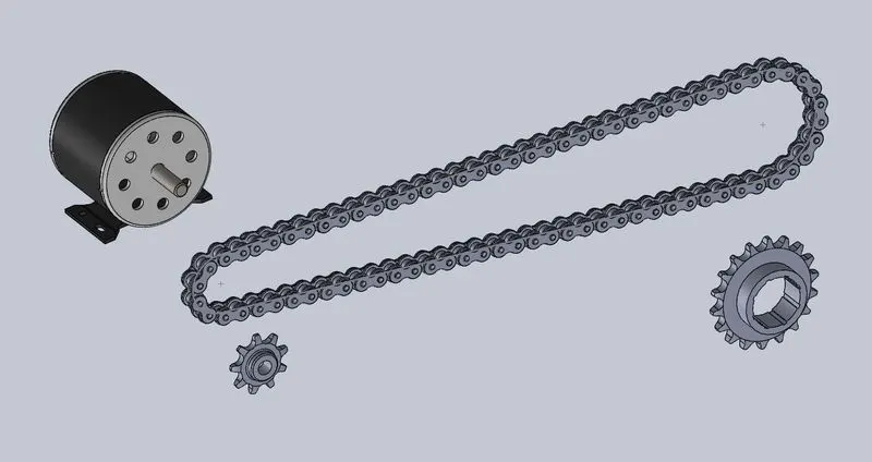
FIG. ASSEMBLY OF CHAIN DRIVE EXPLODED VIEW
3.4.1 Design of sprocket: Total number of teeth on the sprocket is 9.
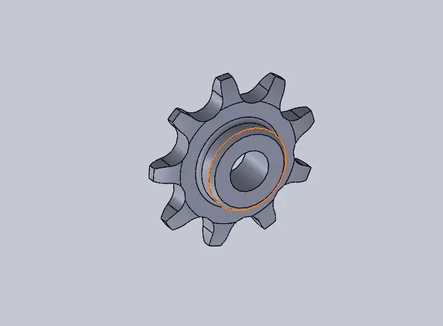
FIG. SPROCKET
3.4.2 Design of freewheels: Total number of teeth on freewheels is 18.
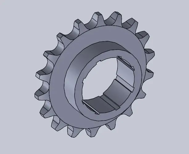
FIG. FREEWHEEL
3.4.3 Design of inner and outer links
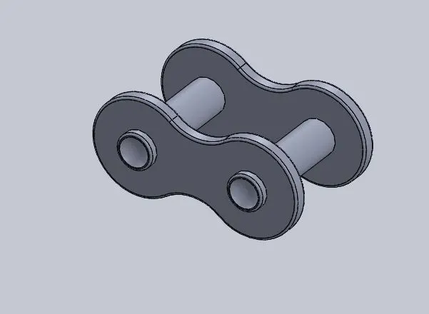
FIG. INNER LINK
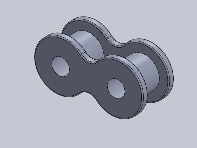
FIG. OUTER LINK
3.4.4 Design of motor
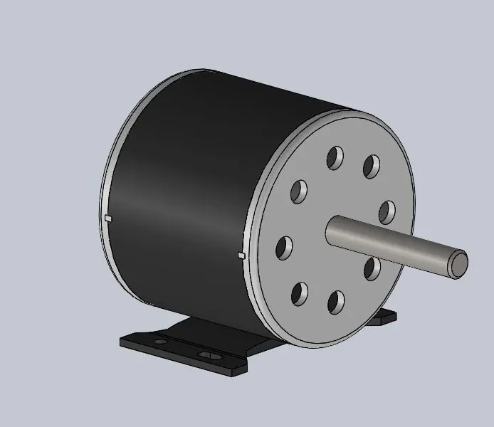
FIG. MOTOR
3.5 Assembly: With the design of all the components ready, it is time to assemble the model. SOLIDWORKS was used to assemble the model. But the problem I faced here was the presence of many components and fine details like threads on bolts etc. This resulted in slow performance of the software as after a point software took seconds to respond to pan command. This made it difficult to work on this software at very early stage when I just finished assembling one side of the steering system and wheel on the frame. At this stage I had more than 100 components in the assembly and if I were to assemble entire model it would easily sum up to might be 400 components which would be chaos in the software. So I came up with a solution which I thought might work (and it did). I deleted the old assembly and started fresh. This approach was based on making whatever unnecessary into one component. For example, collars, mounting plates of collar, brackets were to be fixed anyway to the frame, so I made an assembly in which I properly constrained these parts to the frame and then saved the assembly as part file. So this method made an assembly of say 50 components to 1 component and my aim of making dynamic steering was also achieved. Then in the new assembly, I had just 36 components which were way less than the number of components present in the previous assembly. This method was followed everywhere in the assembly to reduce the number of components. Only the dynamic parts cannot be compromised, everything else was made as a single component. This trick made it possible to bring down total number of components from 300-400 to just 111 in the final assembly.
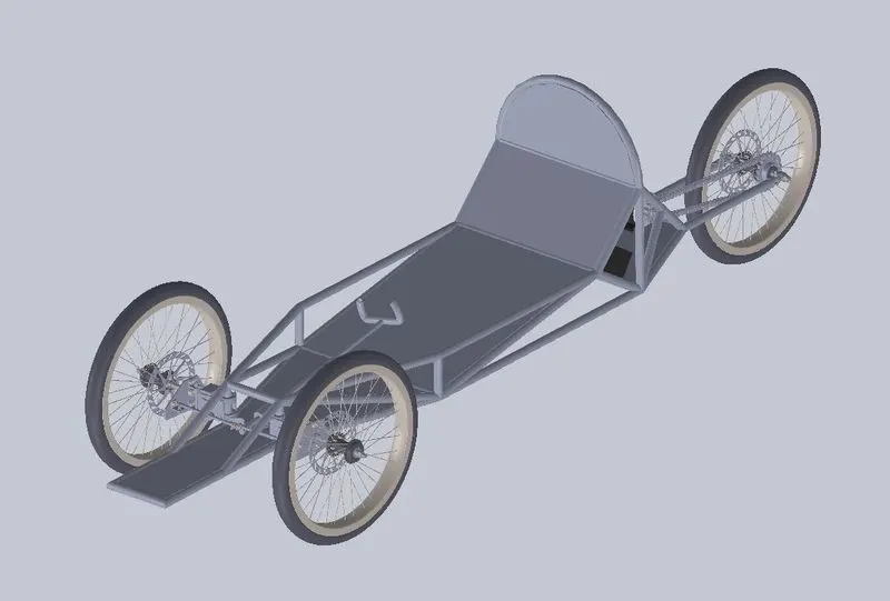
FIG. FRAME OF PROTOTYPE
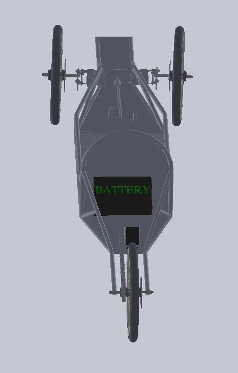
FIG. FRAME OF PROTOTYPE
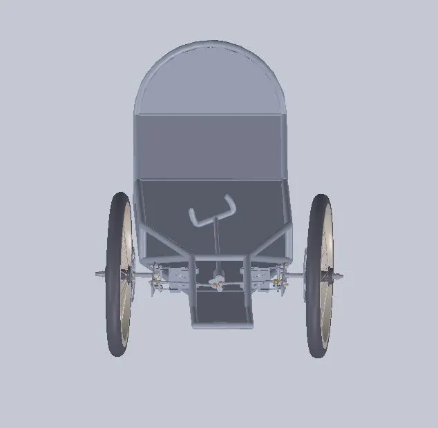
FIG. FRAME OF PROTOTYPE
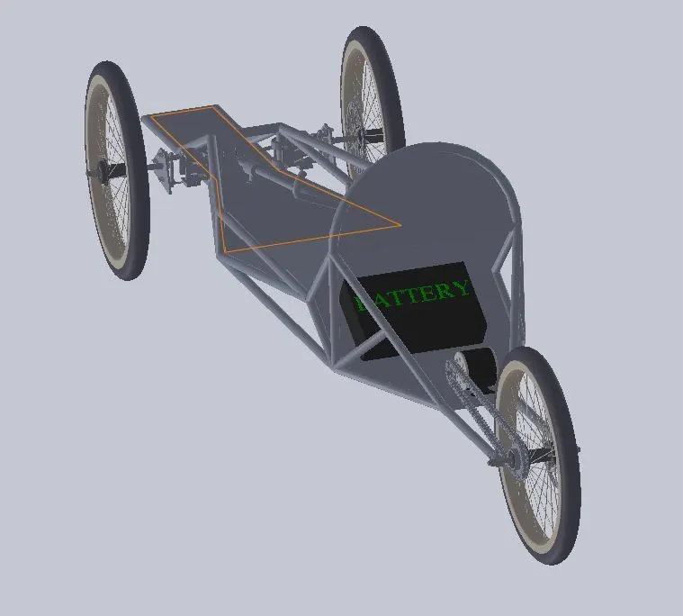
FIG. FRAME OF PROTOTYPE
3.6 Designing body: Usually I would make surfaces in AUTODESK ALIAS, but due to lack of blueprints it was difficult (as I thought earlier) to make a surface for this vehicle. But this problem was solved when I learned CATIA imagine and shape workbench. This workbench allows making unconventional shapes easily as all we have to do is start playing and manipulating a shape till we get our desired shape. But this was not as easy as it sounds. It took around 7-8 tries to get a proper shape and then refine it to make it streamline. But finally, a proper streamline shape was designed. After designing the shape it was edited in generative shape design workbench to split the body into two and make a glass appearance.
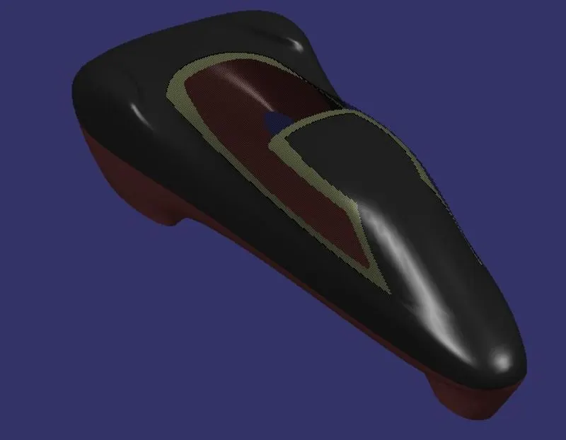
FIG. BODY OF PROTOTYPE
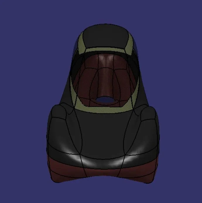
FIG. BODY OF PROTOTYPE
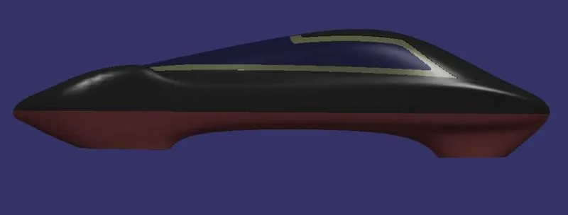
FIG. BODY OF PROTOTYPE
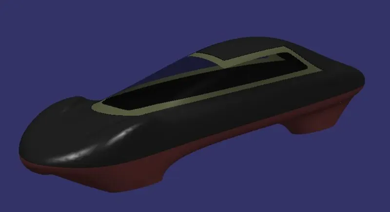
FIG. BODY OF PROTOTYPE
3.7 Rendering: Like decided earlier, the body too was applied carbon fiber material the surface was made aesthetically good. The model was rendered in CATIA itself using different background.
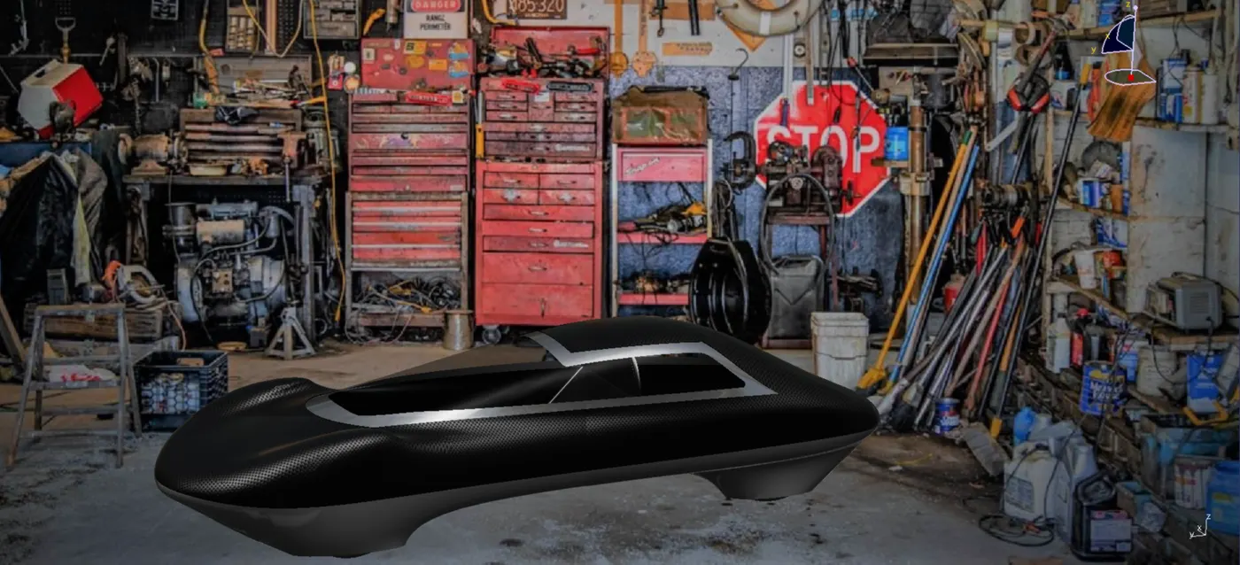
FIG. RENDERED MODEL
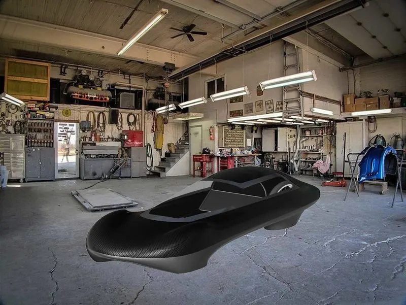
FIG. RENDERED MODEL
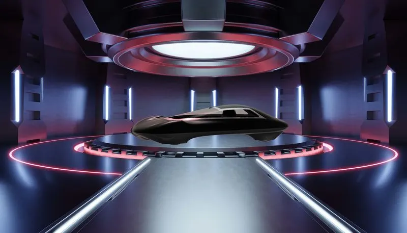
FIG. RENDERED MODEL
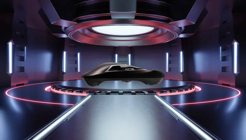
FIG. RENDERED MODEL
CONCLUSION: A complete CAD model of a prototype vehicle for shell Eco-Marathon is designed and rendered.