Child Head Impact
THE OBJECTIVE OF THIS PROJECT IS TO SET UP AND RUN THE SIMULATION FOR HEAD IMPACT ON A RIGID WALL AND ON THE HOOD AND PLOT THE HIC 36 GRAPHS IN BOTH THE CASES.
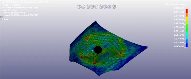
ABSTRACT: About 14 percent of all road fatalities in Europe are pedestrians, with children and the elderly being at the greatest risk. Pedestrians comprise one of the main categories of vulnerable road users, which also include cyclists and motorcyclists. According to the data, 80 percent of the serious injuries are reported to be on the head, 35 percent of the moderate injuries on the head, and 37 percent of the moderate injuries on the lower limbs. Thus, it is important to protect the pedestrian’s head. As it is costly to create an entire dummy human dummy for the analysis and study of the simulations, the industry uses 3 different models (head, upper leg, and lower leg) to study the injuries and crashworthiness of the hood and give a HIC number. In this model, I have simulated the child's head impact on the hood. However, I went through a series of easier stages to reach the required stage.
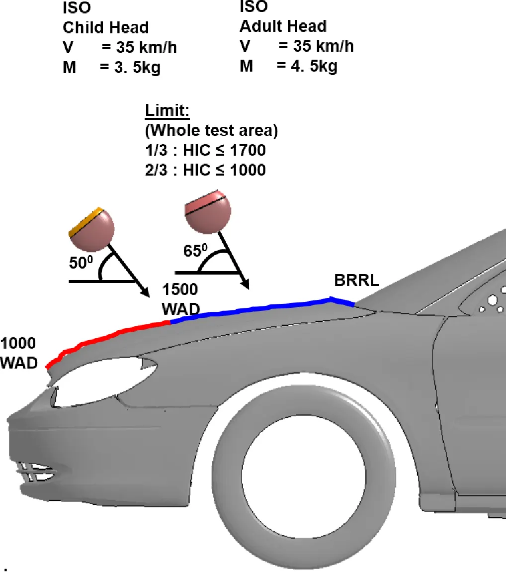
THEORY:
Abbreviated Injury Scale: The Abbreviated Injury Scale (AIS) is an anatomically-based injury severity scoring system that classifies each injury by body region on a 6-point scale. AIS is the system used to determine the Injury Severity Score (ISS) of a multiply injured patient.
|
Level |
Description |
|
1 |
Slight damage to the brain with headache, Dizziness, no loss of consciousness |
|
2 |
Concussions with or without skull fracture, less than 15 min of unconsciousness, detached retina, face, and nose fracture |
|
3 |
Concussions with or without skull fracture, more than 15 min of unconsciousness without severe neurological damage, multiple skull fractures, loss of vision, multiple facial fractures, cervical fractures without damage to the spine |
|
4 |
Multiple Skull fractures with severe neurological damage |
|
5 |
Concussion with or without skull fracture, more than 12 hours of unconsciousness, hemorrhage in the skull, and critical neurological condition |
|
6 |
Death, cervical fracture with damage to the spine |
Head Injury Criterion: It is a quantification of a head injury. Below are some points which help to under this quantity.
- A small HIC value does not mean that the head injuries will be of low levels
- A high HIC value does not mean that the head injuries will be of high levels
- A Higher HIC value means that there is a higher probability of getting a high level of head injuries
For example, HIC=650 mean
- 90% probability of level 1
- 55% of level 2
- 20% of level 3
- 5% of level 4
Thus, even if the HIC value is low, there is a 5% chance of getting a high-level head injury.
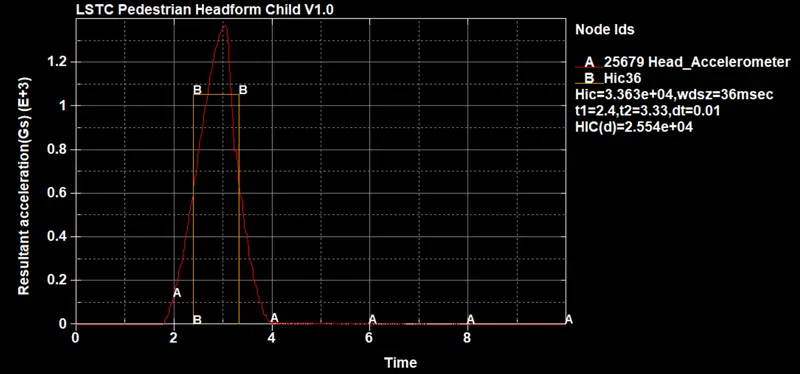
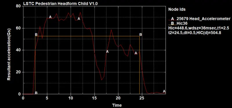
Normally the variable is derived from the measurements of an accelerometer mounted at the center of mass of a crash test dummy’s head, when the dummy is exposed to crash forces.
It is defined as:

Where t1 and t2 are the initial and final times (in seconds) chosen to maximize HIC, and acceleration a is measured in gs (standard gravity acceleration). The time duration, t2 – t1, is limited to a maximum value of 36 ms, usually 15 ms.
This means that the HIC includes the effects of head acceleration and the duration of the acceleration. Large accelerations may be tolerated for very short times.
At a HIC of 1000, there is an 18% probability of a severe head injury, a 55% probability of a serious injury, and a 90% probability of a moderate head injury to the average
PROCEDURE
CASE-1: SIMPLE HEAD IMPACT ON RIGID WALL
Step-1: Defining a rigid wall.
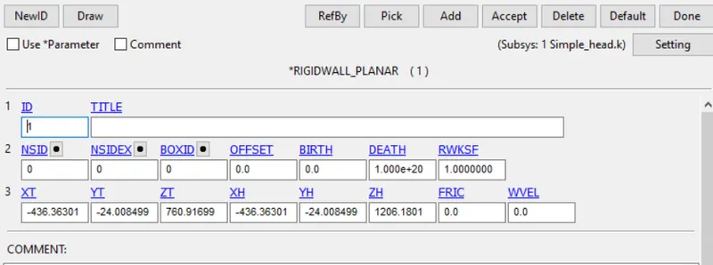
- For this case, I have created a rigid wall parallel to the z-axis in the opposite direction
- Go to entity creation< rigid wall< planer< n+N1 option and select a node
- A wall will be created in the direction normal to that node. Though this is not the required orientation, we will hit accept
- Now, in the same tab modify the wall. Modify< rotate< 90deg along the proper axis to get it in the negative z-direction
- Once it is oriented in this direction, we have to give some gap between the head and the wall
- Modify< trans< 15-20mm in the negative z-direction to get some gap between the wall and the head
Step-2: Creating a section.
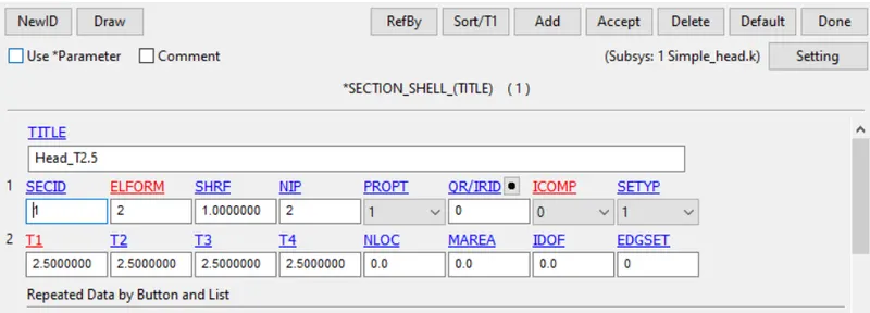
- Go to keyword manager< all< section< shell
- Enter title, section ID, and thickness of 2.5mm
- Hit accept and enter
Step-3: Create a material card
- Go to keyword manager< all< Mat< 024
- Enter the properties of the steel. We can refer to the websites like matweb for the material property data
- Hit accept and done
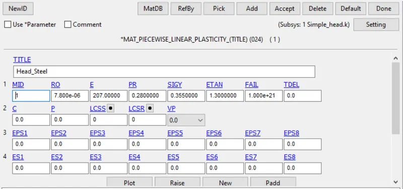
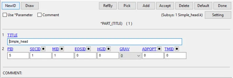
Step-4: Assigning section and material to the part
- Go to keyword manager< model< part
- Assign section and material
- Hit accept and done
Step-5: Define initial velocity
Before creating the initial velocity, we have to create a node-set because the initial velocity card accepts nodes set id. To create node-set:
- Go to entity creation< node set< create
- Select all the nodes of the simple head
- Hit apply
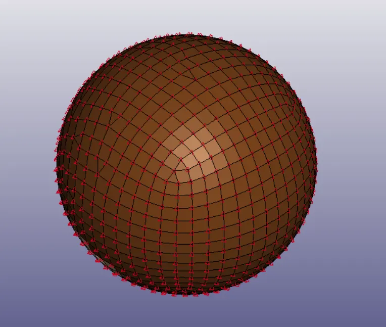
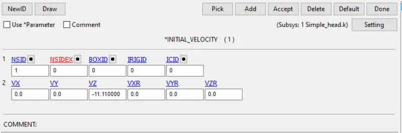
Now, as we have a node-set, we can give a velocity of 40KmpH or 11.11mm/ms to this set.
- Go to keyword manager< all< initial< velocity
- Enter node-set id and velocity of -11.11 under Vz (negative sign denotes negative z-direction)
- Hit accept and done
Step-6: Defining Database cards
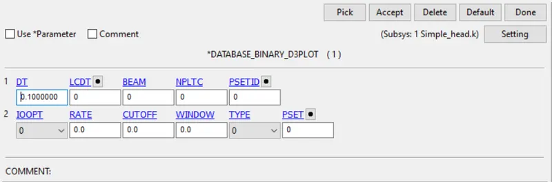
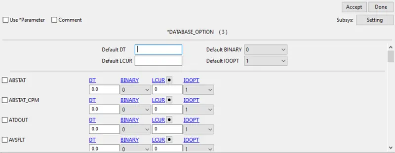
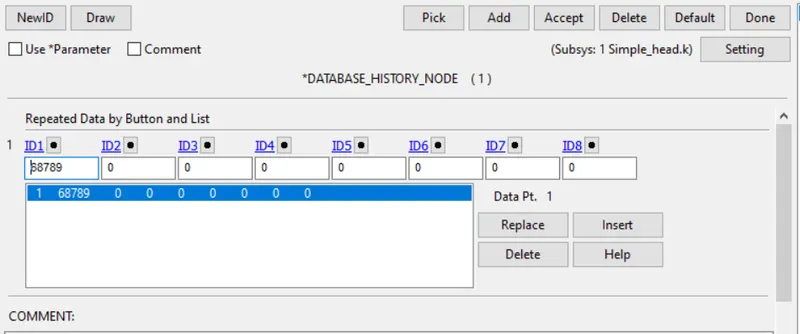
For this case, I have defined 3 database cards. One is a compulsory card that is d3plot. The other two are ASCII and History node. A database history node card is defined to study one of the nodes coming in the rigid wall’s contact.
Go to keyword manager< all< database
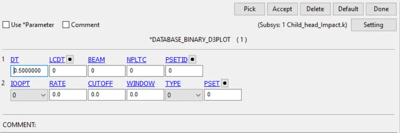
- Database< D3plot< dt=0.1
- Database< ASCII< GLSTAT, NODOUT, RWFORC< dt=0.1
- Database< History_Node< Pick any node that will come in wall’s contact< insert< accept
Step-7: Defining Control cards
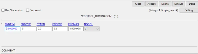
- Go to keyword manager< all< control< termination
- Enter the end time of 3ms
- Hit enter and accept
Step-8: Run the Simulation and plot the results
We can run the simulation directly from the LS-prepost window
- Save the keyword
- Go to file< Run LS-Dyna to open LS-Run
- Now just hit on the run icon
Once the simulation is done, we can plot the results directly from the LS-run window by clicking the LSPP option.
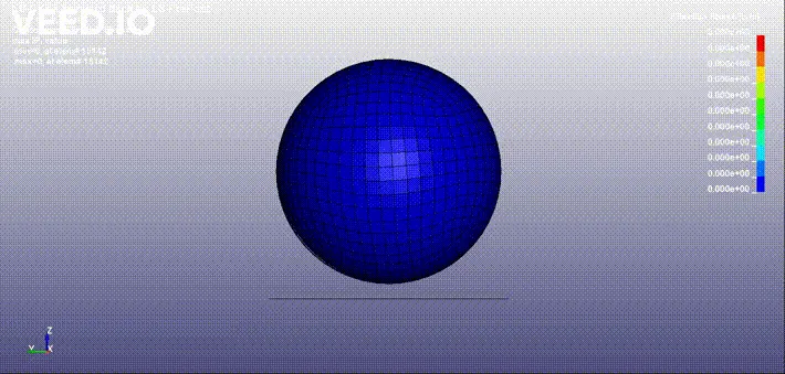
Animation:
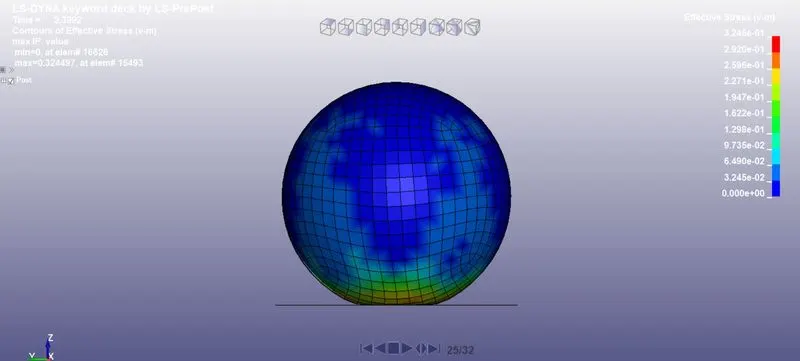
Von-Mises Stress:
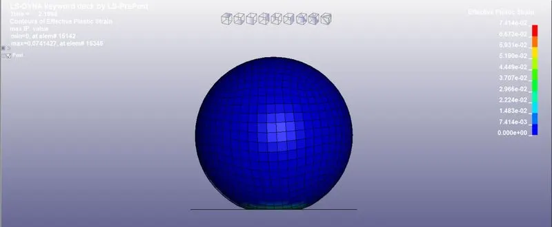
Effective Plastic Strain:
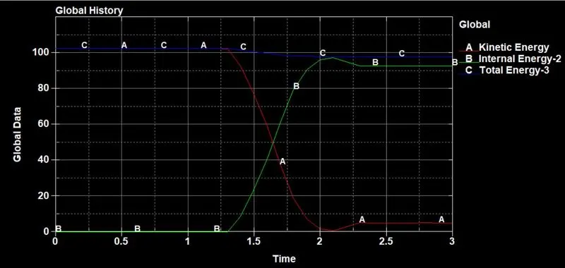
Global Data:
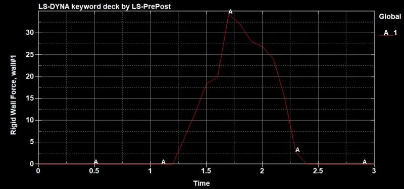
Rigid wall forces:
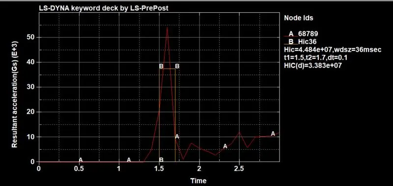
HIC-36:
CASE-2: CHILD HEAD FOAM IMPACT ON RIGID WALL
In this case, we have to work with including transform cards while not disturbing the standard file of head foam.
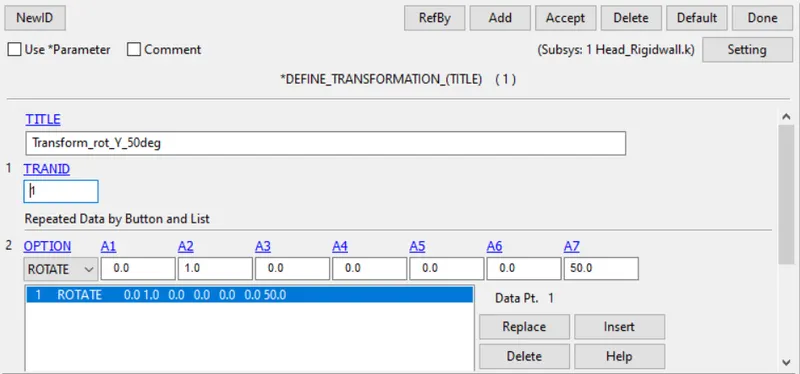
Step-1: Define transformation
- Open a new LS-PrePost window
- Go to Model< Keyword manager< all< define< Transformation
- Give a new id and enter all the parameters carefully. I have rotated around the Y-axis at 50deg
- Hit accept and done
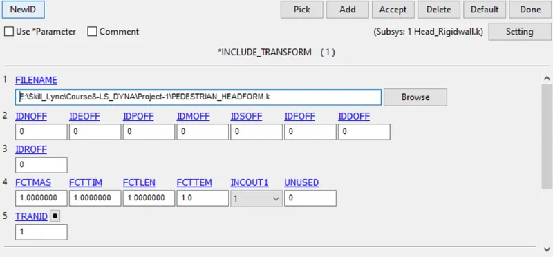
Step-2: Define Include transform card
- Go to Keyword manager< all< Include< transform
- Here, put the transformation id that was created above
- Also, browse for the standard input file
- Hit accept and done
After this step, we would not be able to see the transformation. So, save this keyword and open it again in the new window to see the transformation. Also, make sure that we do not make any changes to the standard file while saving the file.
Step-3: Defining a rigid wall
As we have transformed the head at a certain angle, we have to define the wall carefully. Our wall should be oriented such that it is parallel to one of the global planes and it should seem that the head is aligned at a given angle with respect to this wall.
- Go to Create entity< rigid wall< create< select n1+NL option
- Select a node on the plane surface of the head and play around with Nx, Ny, and Nz parameters to orient the plane accordingly
- This is not the final orientation. Modify the plane using the translate option to translate it to a distance at which we have enough gap between the head and the rigid wall
Step-4: Define initial velocity
Like earlier, we have to create a new set of nodes to define the velocity. The node-set is created in the same way as it was created earlier. However, defining velocity, in this case, is a bit different as we do not have any option (or I am not aware) to specify the inclined direction. Had this been in RADIOSS, we could have created a local coordinate system to define a direction easily. But, in this case, we have to implement the knowledge of resolving the vectors. Simply put, any vector with magnitude A at a certain angle x can be resolved into two components, viz. horizontal component [A.cos(x)] and vertical component [A.sin(x)]. Thus, we need to do a little math and determine the direction and magnitude of the vector to define the initial velocity.
- The magnitude of the vector in our case is 40KmpH or 11.11mm/ms
- This velocity vector is making an angle of 50deg
- Horizontal component: 11.11cos(50)
- Vertical component: 11.11sin(50)
Determining the direction (every case is different)
- It should be moving down. Thus, negative x-direction (in this case). Hence, the vertical component is negative
- It should be moving forward. Thus, negative z-direction (in this case). Hence, the horizontal component is also negative
Defining the velocity using the above data:
- Go to keyword manager< all< initial< velocity
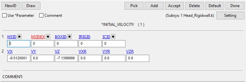
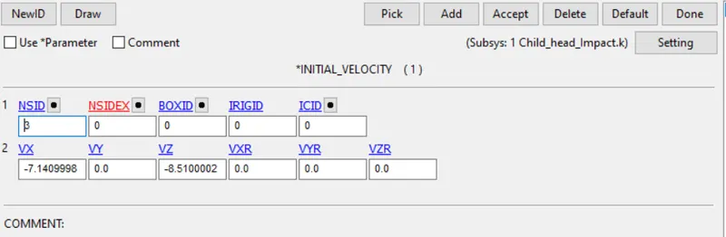
- Enter node-set id and velocity of -8.5120001 under Vx and -7.1399999 under VZ (values are copy-pasted from the initial velocity window)
- Hit accept and done
Step-5: Defining Database cards
Go to keyword manager< all< database
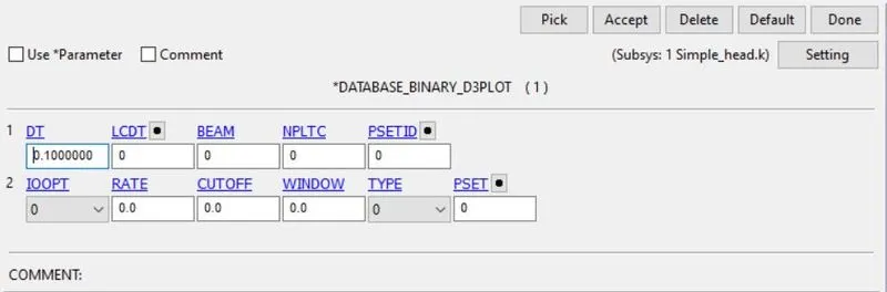
- Database< D3plot< dt=0.1
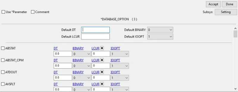
- Database< ASCII< GLSTAT, NODOUT, RWFORC< dt=0.1
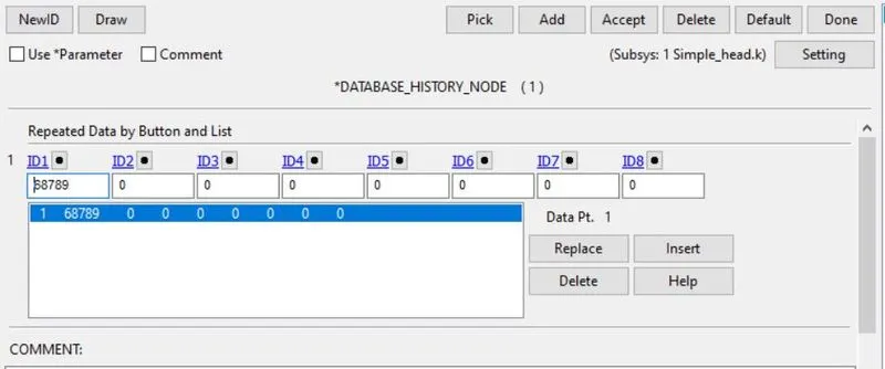
- Database< History_Node< Pick any node that will come in wall’s contact< insert< accept
Step-6: Defining Control cards
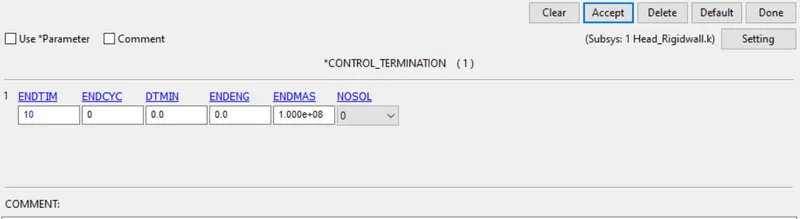
- Go to keyword manager< all< control< termination
- Enter the end time of 6ms
- Hit enter and accept
Step-7: Run the simulation and plot the results
Animation:
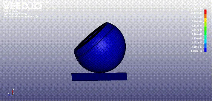
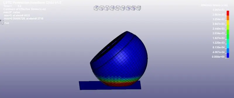
Von-Mises Stress:
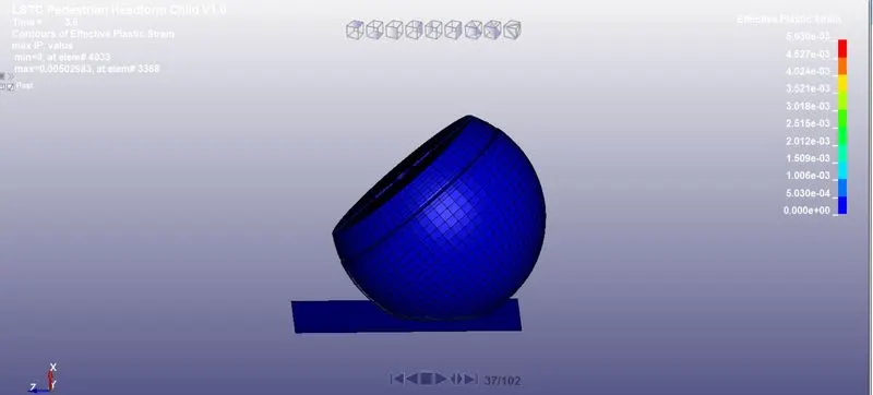
Effective Plastic Strain:
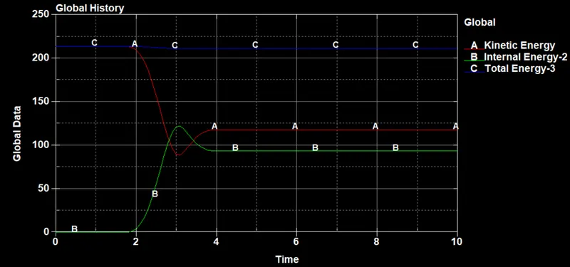
Global Data:
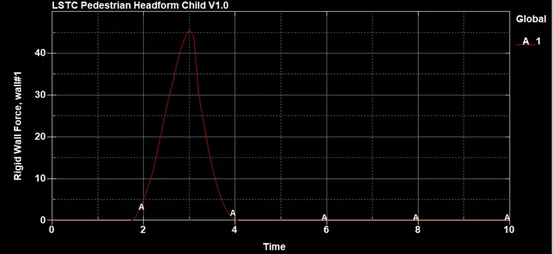
Rigid wall Forces:
HIC-36:
CASE-3: CHILD HEAD IMPACT ON HOOD
Similar to case-2, in this case too we have to use the Include_Transform keyword. Thus, we have to define transformation and include the standard head model as we did earlier. The only difference in this model is that instead of starting from zero, we have to define the aforementioned cards in the provided hood model.
Step-1: Define transformation. (Same as in case-2)
Step-2: Define Include transform card (Same as in case-2)
Step-3: Defining initial velocity
Again, we will follow the same procedure as we have followed for the above two cases.
- Make a set of nodes
- Select this node id in the initial velocity card
- Similar to case-2, we have to give velocity components in this case
Step-4: Defining Database cards. (Same as in case-2)
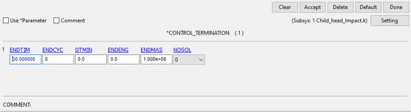
Step-5: Defining Control cards (Same procedure as followed in case-2 with end time 30ms)
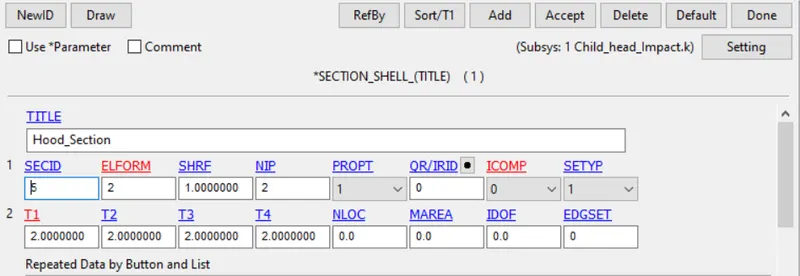
Step-6: Defining Section card for the hood
- Go to keyword manager< all< section< shell
- Change the thickness to 2mm
- Hit accept and done
Note: Usually, the hood component has a thickness of 0.7mm. But, we are running the simulation only on the outer component of the hood. Thus, I have considered the thickness as 2mm.
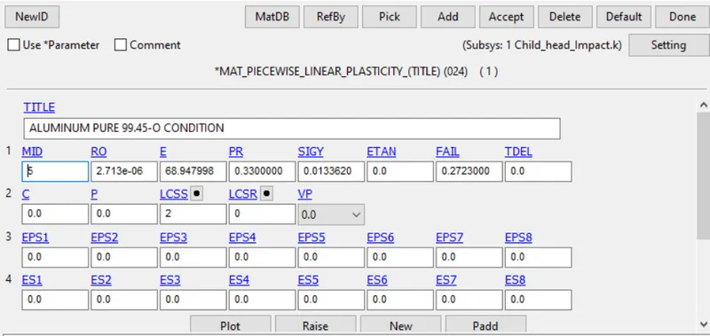
Step-7: Defining material card for the hood
For this step, I have referred to a site Varmint Al’s. As the hood component is made of aluminum, I assumed a random aluminum grade listed on the site. For this case, I have chosen Mat24 failure ALUMINUM PURE 99.45-O CONDITION. This site contains experimental data which can help us in getting proper results.
However, before defining a material card, we should define a stress-strain curve which is listed in the file. This data is experimental and thus accurate.
- Go to keyword manager< all< define< curve
- Load the xy data and insert the file containing this data
- Hit accept and done
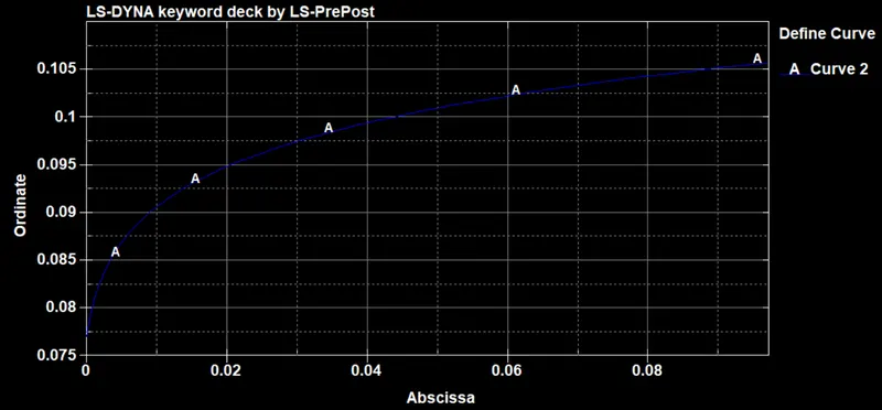
Note: Instead of putting x and y data for the plot one by one, we can load the data directly by saving that data in an excel sheet and using the load xy data option.
Once our curve is defined, we can create a mat24 card.
- Go to keyword manager< all< mat< 024
- Copy and paste all the data listed under ALUMINUM PURE 99.45-O CONDITION
- Load the LSSR curve
- Accept and done
Step-8: Assigning material and section
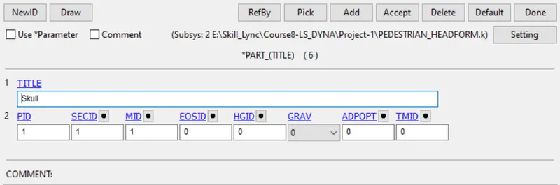
- Go to keyword manager< model< part< hood
- Assign material and section
- Accept and done
Step-9: Defining contact
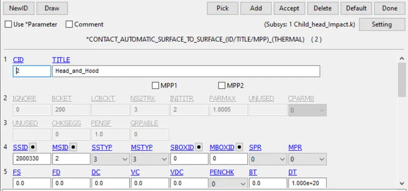
- Go to keyword manager< all< contact< automatic surface to surface
- Define hood as slave and head as master
- Accept and done
Step-10: Run the simulation and report the results
Animation:
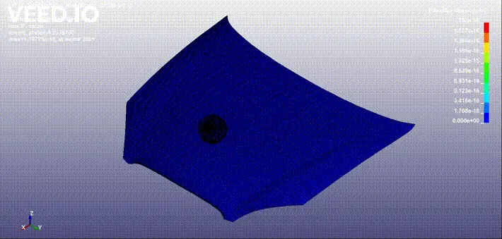
Von-Mises stress:
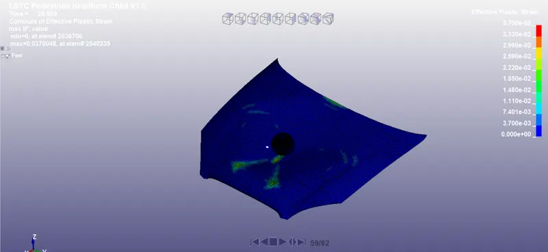
Effective plastic strain:
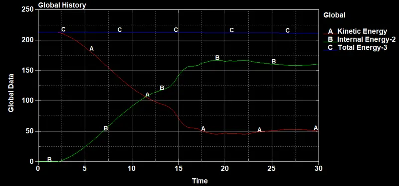
Global Data:
HIC-36:
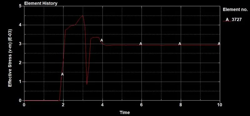
COMPARING CASE-1 AND CASE-2 STRESS/STRAIN CURVE
CASE-2
CASE-3
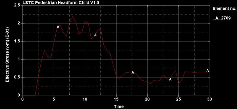
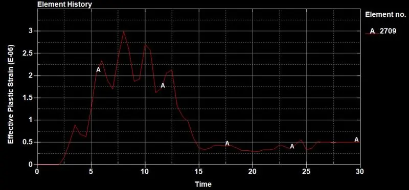
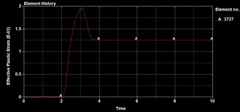
There is a clear difference between the stress and strain curves in both cases. This is due to the surface they are colliding on. In case 2, the head is colliding on a rigid surface that would not deform under any condition. Thus, there is a big deformation in the head model because of the velocity. However, in case 3, the head is colliding with the hood which deforms after the impact. The hood absorbs the energy and thus there is less stress om the head model when compared to the case-2 model.
CONCLUSION:
- Case for simple head colliding on the rigid wall has been successfully simulated
- A child's head colliding on a rigid wall at an angle of 50deg has been successfully simulated
- Child head impact on the hood has been successfully simulated