Project-Meshing of Door Inner Panel
MESHING OF THE DOOR PANEL
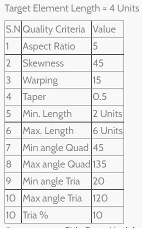
OBJECTIVE: Aim of this project is to mesh the given door trim along with all its feature like ribs, dog-house, etc. while maintaining proper mesh flow and connectivity between the parent geometry and the features.
REQUIREMENT:
THEORY:
2-D MESHING: We opt for 2D meshing whenever the thickness of the component is 5mm or less. Creating a mesh with 2D elements will reduce the number of elements in the component and also the time required to solve the problem. Thus, whenever we have a part with a thickness less than 5mm, we should mesh it with 2D elements.
Thumb rule for handling tria elements in the model: As we are creating a mesh with mixed elements, it is natural to get tria elements in the mesh. Moreover, it is not possible to completely eliminate the tria elements. However, we can reduce the number of tria elements in the model. We should keep the following points in mind while handling the tria elements:
- No tria elements should be opposite to each other.
- No tria elements should be connected back to back.
- No tria elements should be on the edge of the geometry.
- No tria elements should be near the holes.
- No tria elements should be on the features.
- There should be less tria concentration at a place.
MANUAL MIDSURFACE EXTRACTION: When dealing with plastic components, it becomes necessary to extract the mid-surface manually because it does not have a uniform thickness. Some parts of the component might have x thickness and some parts of the same component might have y thickness. Even if this practice creates problems during multiple stages of the product development process, it fulfills its main purpose of making the component aesthetically good. Thus, we have to follow the below-mentioned steps for extracting mid-surface manually:
- Create a new component and name it as mid-surface_Txx
- Measure the thickness of the component and include that in place of xx
- Make it a current component
- Go to surface-edit< offset
- Select the surface that we think should be the mid-surface of the part.
- Click on the surface and duplicate them in the current component.
- Insert the offset value, check the normal, and offset the surface to get the mid surface of that feature.
- A similar process must be repeated for every feature.
CREATING AND ASSIGNING PROPERTY: Once we complete the meshing part of the model, we can assign property to the component. As in the plastic component the thickness is not uniform, we have to give utmost attention while assigning thickness to the parts. To ensure that every part gets proper thickness we must follow the below steps:
- While creating mid-surface, name the component as midsurface_Txx where xx is the thickness of that part.
- Repeat this for every feature in the model.
- Right-click and create the property and name it as Txx.
- Assign xx thickness to the property.
- Click on the mid surface of the component and assign the property according to the thickness.
CONNECTING THE MID-SURFACE: After extracting the mid-surface, the surfaces are connected to each other like they were in the parent geometry. Thus, to stitch them, follow the mentioned steps:
- Go to Geom< surface edit< extend
- From the drop-down select extend over edges and by distance and mention a random distance value
- Extend both the surfaces to be joined
- Go to Surface edit< trim with surfaces/plane
- Select the surfaces to be trimmed and check the trim together option
- Delete the extra surfaces.


PROCEDURE:
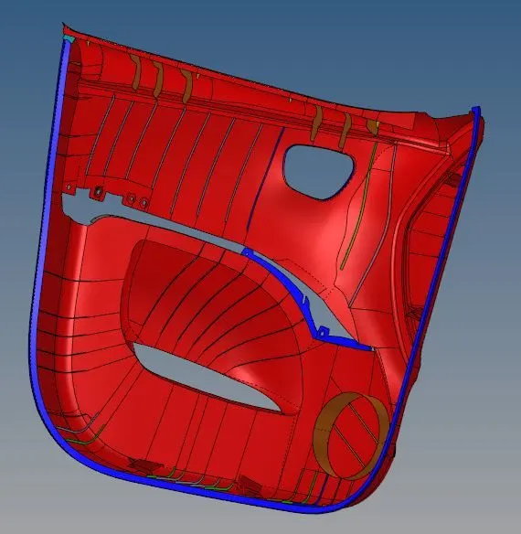
STEP-1 Bifurcating the component: The provided input file is complicated to work on. This might create confusion later. So to make the process easier, we must divide the component in different parts. Following operations were carried out to simplify the operations:
- As plastic components comprise A-surface, B-surface, C-surface, and features on the B-side, I have created 2 components for A-side and B-side.
- Select the surfaces on the A-side of the component and move them to the respective named component.
- I also observed that the component has a flange, so I created a new component for that flanges and moved those surfaces too.
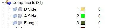
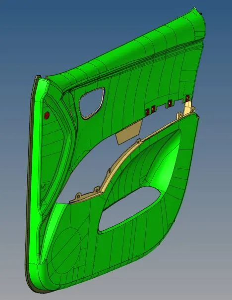
STEP-2 Extracting the Mid-surface: The process to extract the mid-surface manually as mentioned above. Follow the same process to get the mid surface here. Mentioned below are the steps in which I extracted the mid-surface.
- Extract the main mid-surface from the A-side of the component manually.
- Extract the flange mid-surface manually.
- Extract the mid-surface of the features like ribs and dog house manually.
To extract the mid-surface of the ribs, we can also use the following steps:
- Go to Geom< mid surface.
- From the drop-down, select final edit tools
- Select the two opposite surfaces of the ribs
- These options will create the mid-surface between these selected surfaces.

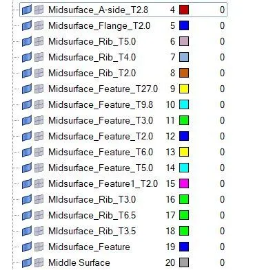
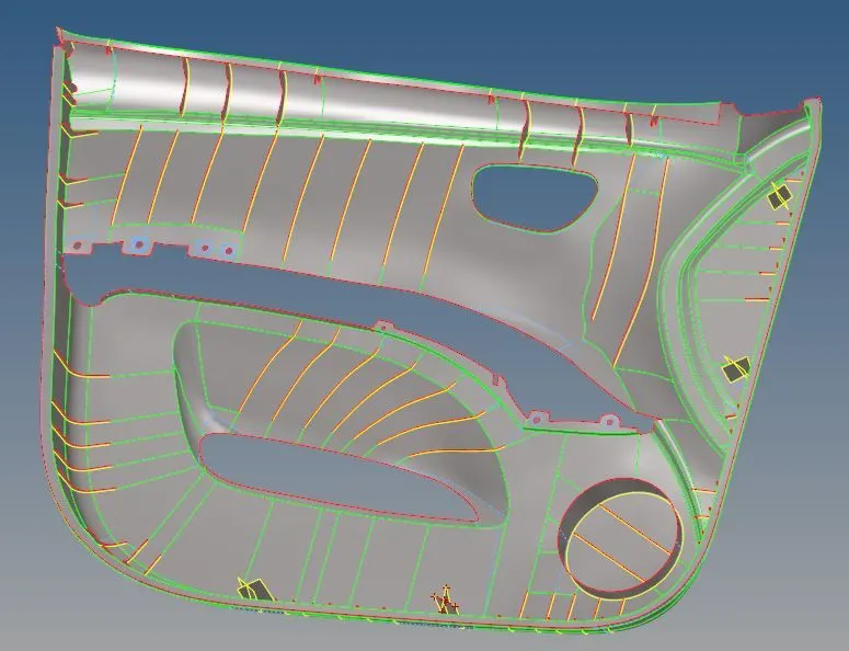
STEP-3 Geometry Clean-up: This is the most crucial stage in the process of meshing as it determines the quality of the mesh. A good clean-up can give us a very good quality mesh, but a bad improper clean-up will give a mesh that we will have to refine a lot. Following steps should be carried out in the clean-up process.
- Combine main mid-surface and flange.
- Combine ribs and other features with the main mid-surface.
- Use defeature option to remove small fillets that will lead to failing the elements under minimum element criteria
- Use quick edit panel tools like toggle edges to suppress unnecessary edges.
- Trim the geometry wherever required and mostly to make square and rectangle shapes.
- Use replace points options to merge nearby points
- Use add/remove point options to remove unnecessary points in the geometry.

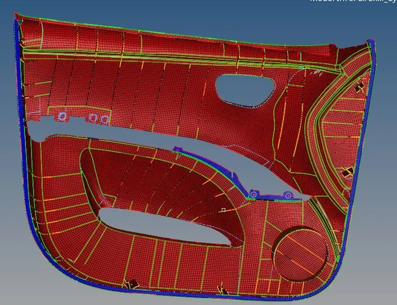
STEP-4 Creating mesh and controlling the flow: After cleaning up the geometry, we have to mesh the component and ensure all the elements are good. We can create a mesh in one step by selecting all the surfaces together. But, to get proper control over the mesh flow, follow the below process.
- As in the clean-up process, the component was divided into many small surfaces, I preferred to mesh them one by one.
- Go to auto mesh < select surface and element length as 4 units and create a mesh.
- Manipulate the nodes to reduce the number of tria elements.
- Go to quality index< set the parameter and check if any element is failing. In such cases use an element optimization tool or remesh the elements.
- In some cases, we have to split the elements, combine, delete and create the elements.
- In some cases, we have to project the nodes on the line or the surface.
- Once all the elements are good and the flow is proper, then we move to the next patch of the surface and repeat the same procedure.
- Repeat this procedure until our entire component has meshed properly.
- In the end, assign proper thickness to every feature of the component.
FINAL MODEL:
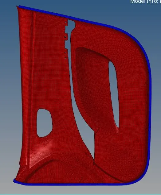
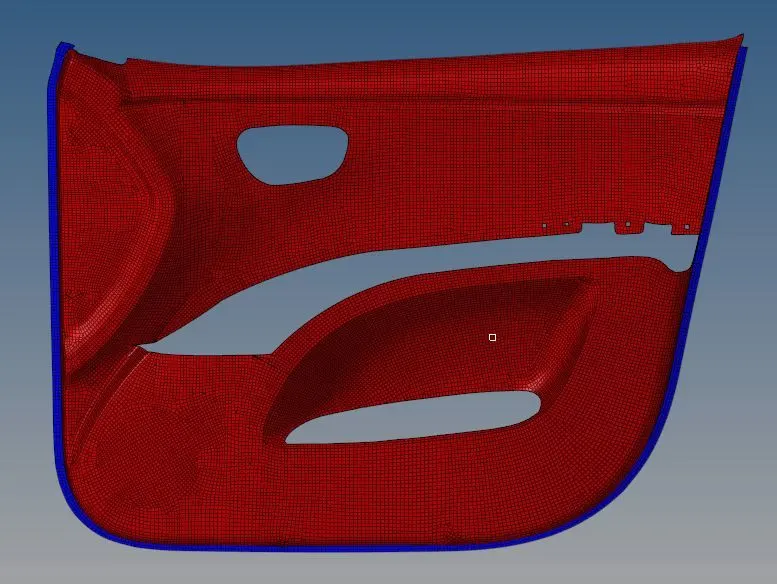
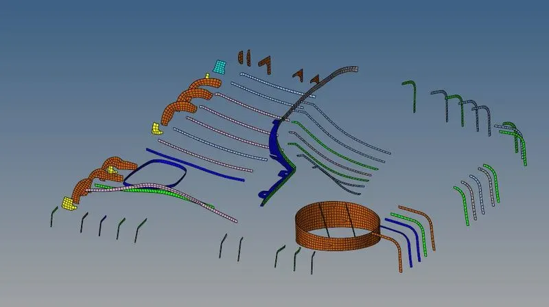
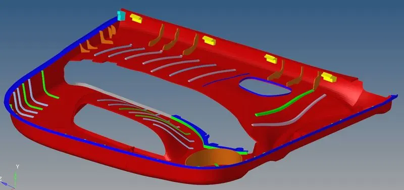
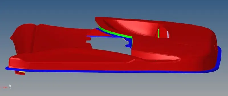
CONCLUSION: In this challenge, I have learned to mesh the plastic component using manual mid-surfacing and assigning multiple thicknesses to different features of the same component.