Roof challenge
DESIGN OF CAR’s ROOF
OBJECTIVE: Objective for this project is to design all the rails of the roof from the given skin and to justify the positions of the rails.
ABSTRACT: A car’s roof is to ensure the safety of the occupants in different weather condition and especially in case of accidents. The most important role of the roof comes in the roll over crash. This is the most critical crash that can happen as and when it happens the roof tends to cave in on the passengers and injure them. To avoid the caving in of the roof or minimizing this effect, we must have a strong roof. For making a strong roof we have to take care of lot of design consideration from making strong rails to positioning them at proper regions. This is a detailed report on the designing part of the roof.
THEORY: There are few points we, as designers, must keep in mind before designing the roof.
- Flat roof is weaker than curved roof. Hence bow roof rails should be positioned on the flat part of the roof to increase the strength of that region.
- Number and position of the bow roof rail depends on the length and curvature of the roof. A small roof with a good curvature might require just one bow roof rail.
- We must stick to the master section as that sketch is prepared keeping every other criteria and dimensions in mind.
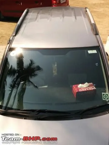
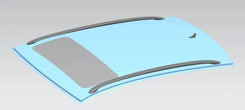
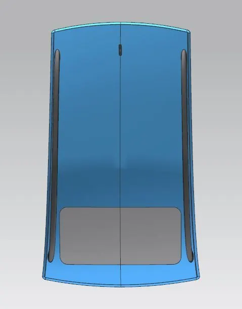
- If we are giving embosses on the outer roof for aesthetic purpose or for increasing the strength, it must be designed keeping all the variants in mind. Higher variants or variants of other countries might have sun-roof. This is can be seen in the image below. The emboss covers only half of the roof so there is enough space for the sun-roof.
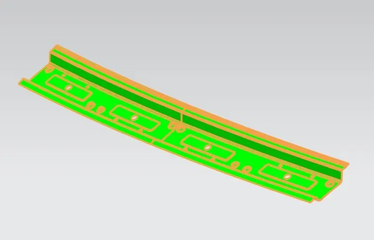
FRONT ROOF RAIL (FRR): FRR acts as reinforcement and also as a support for the bracket map lamp and room lamp. Apart from this it joins windshield glass and body side outer. To design this rail, master section is followed for the reasons which are explained below.
MASTER SECTION OF THE FRR:
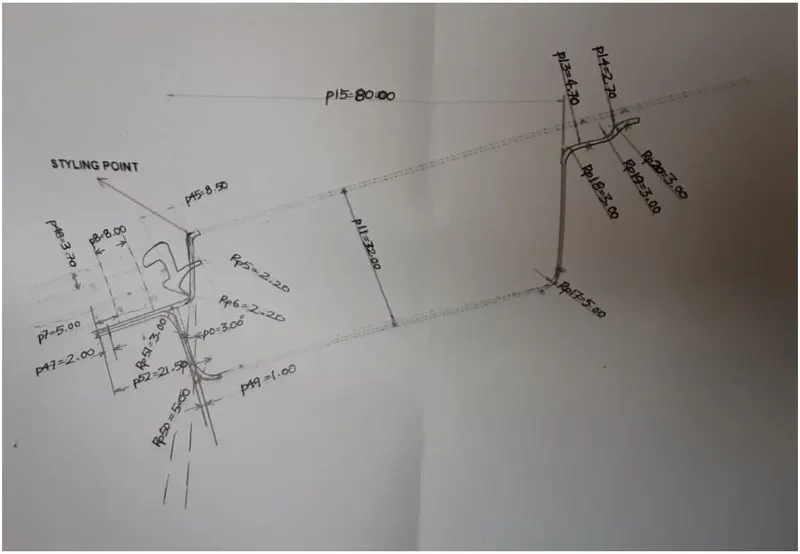
- The extension is opened at 3deg from the vertical for the deep drawing reasons. If we decrease this value to 2deg then the part will not be drawn and if we increase this then the connected flange might extend beyond the front visibility line set by project management team and thus will hamper the front visibility of the driver.
- The flange has a length of 21.5mm as it accounts for rubber gradient line length, molding length and dimensions of the windshield glass. Going beyond this length might hamper front visibility criteria.
- The flange is at some offset distance from the roof to account for the thickness of windshield glass, surrounding sealant and rubber paste which will sit on the flange.
- The lower offset surface is at 32mm as it depends on the front visibility line given by the project management team. We can edit this as long as it does not hamper the visibility criteria.
- The 80mm distance is for the head room clearance for the front seat occupants. The position of the driver is decided by the project management team and then the master section is prepared accordingly.
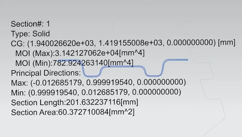
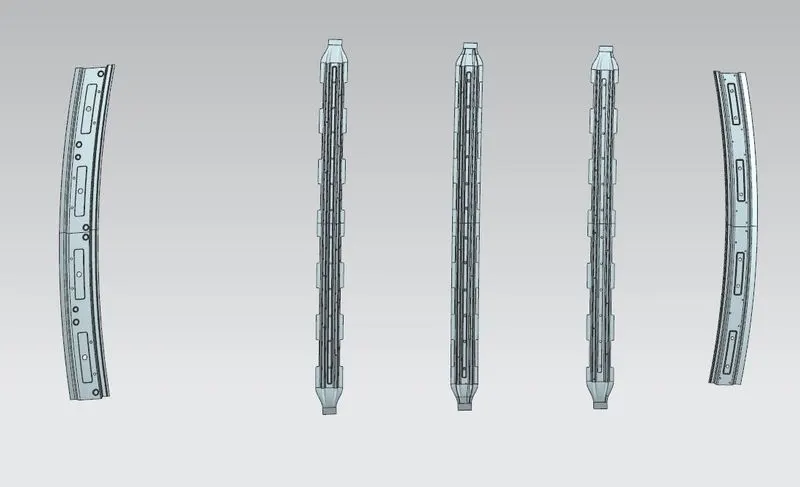
Following the above master section, the below FRR is designed. Later, draft analysis study and section inertia study is carried out on the component.
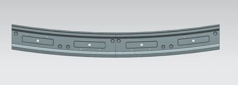
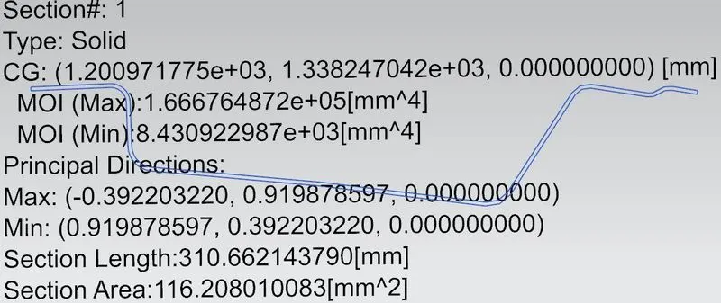
REAR ROOF RAIL: Apart from acting as reinforcement for the roof, it also has other functionality like joining to the back door and to the body side outer. This component also is designed after following the master section. After the completion of the component, draft analysis study and section inertia study is carried out on this.
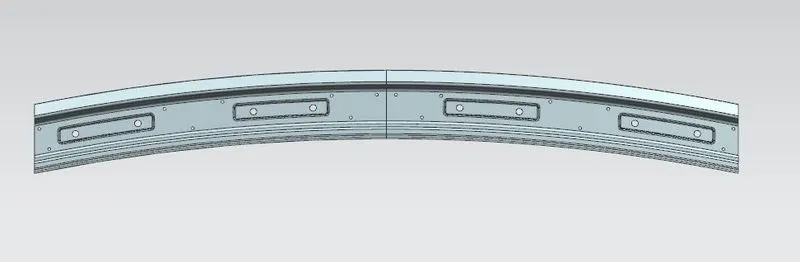
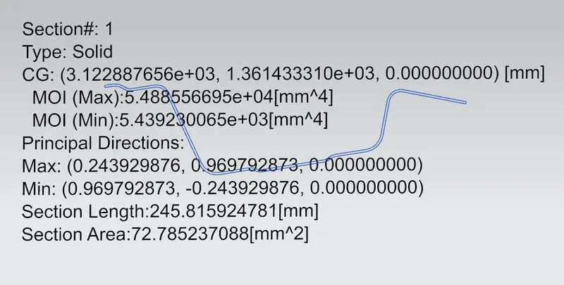
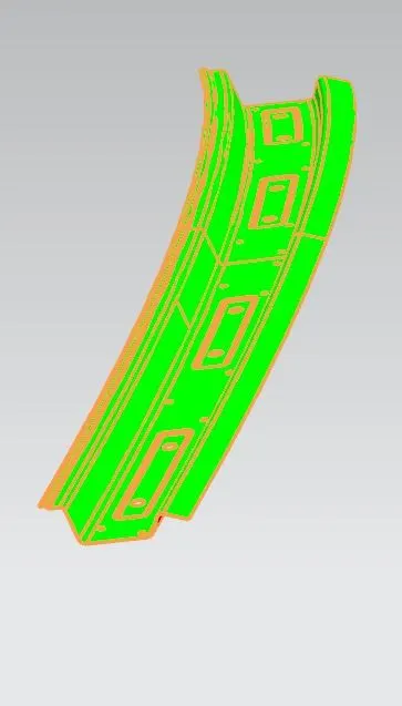
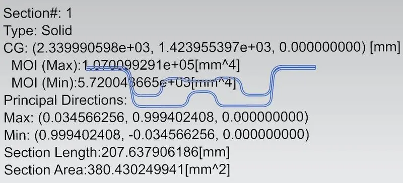
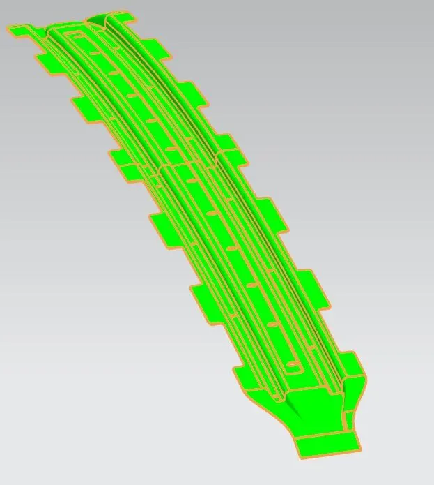
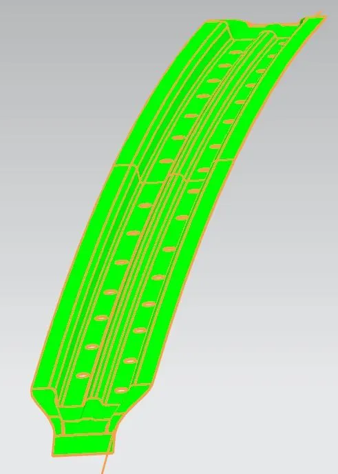
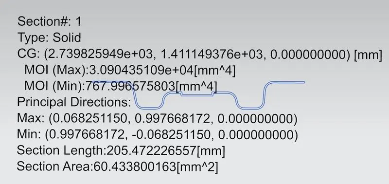
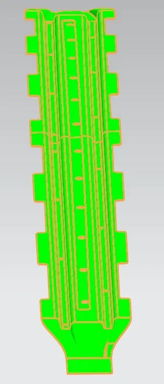
BOW ROOF RAILS (BRR) AND ROOF REINFORCEMENT CENTRE (RRC): Both of these components are positioned to increase the strength of the roof. In this design as there is a sunroof, the position of BRR2 and RRC is at the same point. BRR2 is inside the RRC. This is done to account for the strength of the roof. Has the sunroof been in the roof, the position of the BRR2 might have been ahead or behind the RRC. A master section is followed to design these components too. Main concern is the head room clearance for the passengers. Once the components were designed, draft analysis study and section inertia study was carried out on them.
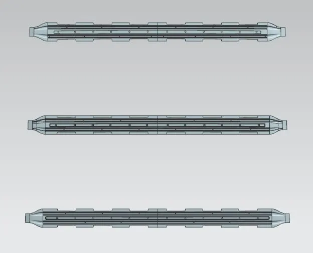
BRR1
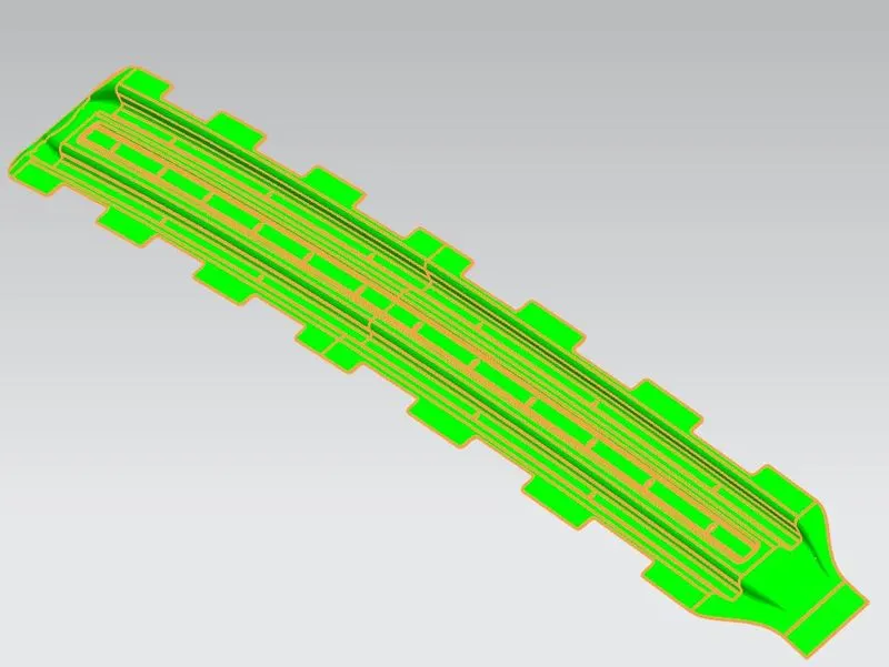
BRR2 & RRC
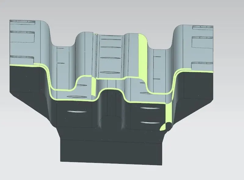
BRR3
CHECKING IF THE ROOF IS GOOD OR NOT
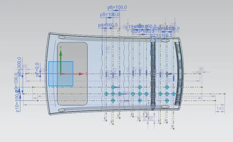
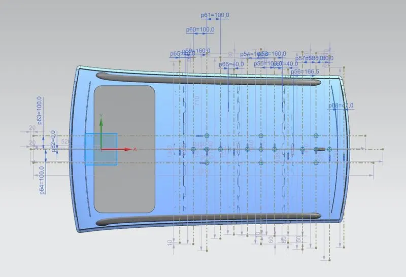
At design level, we can do a curvature study to see if the position we have given for the BRRs and RRC is proper or not. For this we have two conditions:
- Heat distortion criteria
- Snow Load condition
HEAT DISTORTION CRITERIA:
W = [1.73 x 10^ (-3) x L] + [1.85 x 10^(-8) x (R^2)/t] + [ 1.10x10^(-3) x l] - 2.68
Judgment Condition: OK< 2.7> 3.1
Where,
L = Roof Length in X-Direction [mm] (Roof dimension in 0-Y)
R = Roof curvature
R = 2(Rx*Ry)/(Rx+Ry)
Rx = X curvature
Ry = Y curvature
t = Roof plate thickness [mm]
l = Bow Roof Span [mm]

SNOW LOAD CONDITION:
Qr = [Iy x t2] / [α x s x [(Rx + Ry)/2]2 x 10-8]
Where
α = My x Lx2 x 10-12, My = Y(Ly-Y)
Judgment condition = Qr ≥ 3.1
250 ≤ s ≤ 380
t = Roof plate thickness [mm]
Ly = Distance between the front and rear roof Rails on the Vehicle along with 0Y[mm] Length of Roof panel with the center point between Roof rail Front /Rear as the reference point of the front and the rear.
Lx = Distance between the Left and Right end of the roof on the Roof BOW [mm] Width of the roof panel exposed on the surface.
Y = Distance front Roof Rail to Roof BOW[mm]
s = Distance for which Roof BOW bears divided load [mm]
s = L1/2 + L2/2
Iy = Geometrical moment of inertia of Roof BOW (Y cross-section) [mm4]
Rx = Lateral direction curvature radius of roof panel Y cross-section on Roof BOW [mm]
Roof panel curvature Radius of the Length Lx in Front view
Ry = Longitudinal Direction curvature radius of the Roof panel X cross-section on Roof BOW [mm]
Roof panel X curvature radius of length s in Side view

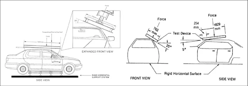
Once the BIW of the car is ready, we can check the strength of the roof by ‘roof crash test’. In this test a load is applied on the roof and its deformation is noted. Ratings are given on the basis of how quickly the car reform to the original shape and how deep the protrusion is. Below images and video shows the set up and the process of the roof crash test.
LINK TO THE VIDEO: https://www.youtube.com/watch?v=F3TwtrAxua0
IMAGES
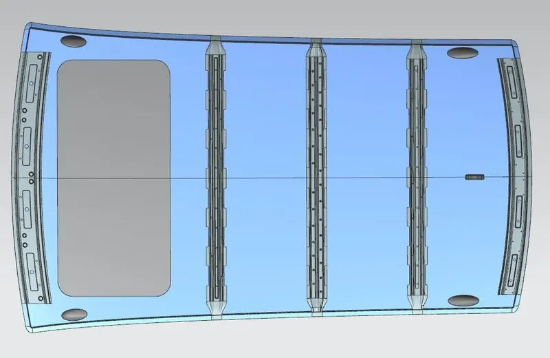
CONCLUSION: The position of the Bow Roof Rails is proper.