2D Meshing
2D-MESHING
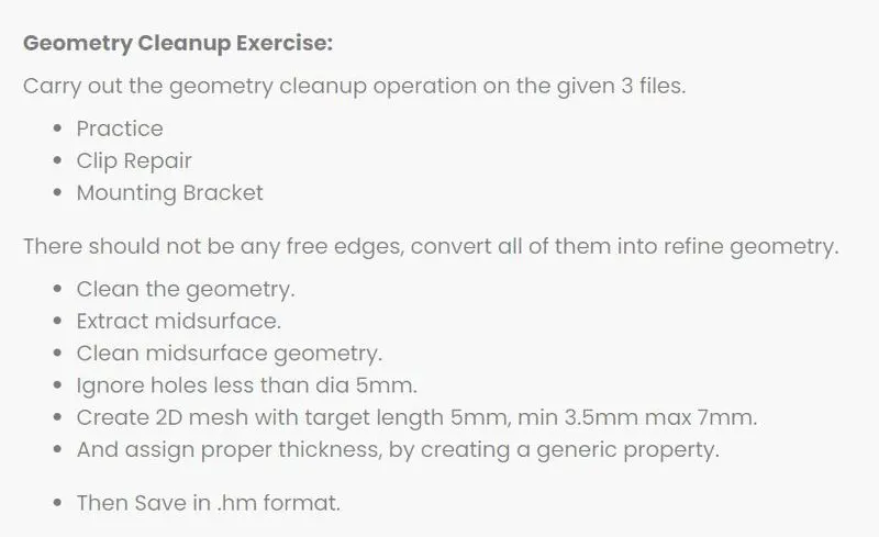
OBJECTIVE: Aim of this project is to mesh the given components while maintaining proper mesh flow, capturing features to the nearest, and assigning thickness.
REQUIREMENT:
PROCEDURE:
EXTRACTING MID SURFACE: Mid-surface can either be extracted manually or by using auto-midsurface. The manual extraction method is generally used for plastic components due to its non-uniform thickness throughout the model. As sheet metal component has a uniform thickness, we usually use the auto-midsurface option. However, in some cases where features create complexities while extraction, it may lead to deformities in the mid-surface, and thus in such cases we use manual extraction in sheet-metal components too. In this model, I opt for auto-midsurface option. Given below is the procedure to extract the mid surface:
- Go to Geometry< Midsurface
- Under extraction option, choose offset+planes+sweep
- Under auto extraction choose all the input surfaces and hit extract to get a mid-surface.

GEOMETRY CLEAN-UP: This is the most critical part of the process of meshing as it determines the mesh flow. Some things should be taken care of in this step in order to reduce the laborious task later. There are some thumb rules that help me initiate this step which is listed below:
Look for any merging features. This can usually occur in the regions where two features like fillets tend to converge which creates a triangular area where we know that our requirement of minimum element criteria will be failed. Thus, we must make prior arrangements using the quick edit tool to eliminate this scenario. This can be done in a few ways, but the most effective way is to follow the curve and split in a manner that we can capture the feature without compromising with the element length.
Reduce the number of construction lines. In geometry, we can find two types of lines. The lines which define the features are called feature lines. For example, the lines that we see on either side of the fillet are feature lines. And rest of the lines are construction lines. For example, the lines that appear on the flat surface and they will not create any changes to the geometry even if they were not present are construction lines. This will result in less number of surfaces in the geometry.
Reduce the number of points in the geometry. The elements in the mesh tend to be on the points of the geometry. For example, if there are 10 closely related points, the elements will have their ends on these points. This will lead to the failure of elements. Thus, we should keep an eye on extra points in the geometry and remove them. In addition to removing the extra points, we must also eliminate the close points by replacing one with another. This will ensure that there is only one point in that region and we will get a proper element.
Divide the surface into square or rectangular patches. When a flat surface is divided into square or rectangular patches, we can be assured that there will only we quad elements in that region. This will improve the mesh quality in general and also make the mesh look good.
Divide the circular region into two parts. If not divided, the circular region will have rotating quad elements which are undesirable. Thus, by dividing the model into two, we eliminate the possibility of the undesirable pattern.
Toggling the unnecessary free edges: When we open the model, there might be many edges that must be joined and displayed in green rather than red. These red edges depict the non-connectivity in the model and thus must be taken care of. We can use the toggle option for minute gaps in the model. However, for large gaps, we must manipulate and create new surfaces.
Tackling small holes: According to the question, we must ignore the holes less than 5mm dia. Thus we should measure the radius of the hole and if it is less than the mentioned value, then we must use the filler surface option to fill that hole.
MESHING THE COMPONENT: We can either mesh the cleaned-up mid-surface in one shot or go on meshing surface by surface. In the former method, we have less control over the flow of the mesh as compared to the latter. Thus, I choose to mesh the model surface by surface. Even if this process takes more time in meshing, we usually have to spend less to no time refining the mesh after the entire mesh is completed because this step is performed simultaneously while meshing. In addition to this, we can also control the mesh quality simultaneously.
- Go to 2D< automesh
- Select the surface to mesh. Give element size as 5 units and mesh the surface.

To refine this mesh, we must use options like rebuild mesh or use automesh on the elements again. This step will reduce the number of trias in the mesh. In addition to this, we must also use the smooth option to refine the mesh.
- Go to 2D< Rebuild mesh< Select the elements (try to select in square or rectangular patches)
- Go to 2D< Smooth< Select elements and refine those elements
One of the most common problems that we face in this method is the connectivity issues with the other patches. After refining and rebuilding the mesh, we might encounter free unnecessary free edges in between the mesh which must be taken care of. The best method to do this is to check the free edges from time to time while meshing and resolving the issues.
- Go to tools< Edges
- Select all the elements and click free edges
- Change the mesh visuals to by comp and hide the component and mesh to check the free edges
- We can equivalence some nodes with 0.01, 0.1, and 1 tolerance. But, in case of more tolerance use replace node command (F3)
Repeat these steps for every patch of the surface to get a good mesh. Further, we can reduce the time taken to detect the failed elements by going to the quality index again and again by just keeping the mesh visual as by quality index. In this way, we can detect the failed elements while we are meshing and we do not have to go to the quality index to check the failed elements.
To avoid the problem of connectivity, we should abstain from remeshing the elements near the points. As the rebuild mesh option generally displaces the element from the point, it results in no connectivity with the adjacent surface which has its elements on the line and at points. Thus, not meshing the elements on the edges will not create the free edges problems.
ASSIGNING THICKNESS TO THE MODEL: We assign thickness to the model in order to represent it as closely as we can to the model we had as input. As we mesh the midsurface and not the 3D model, we must make this mesh 3D by assigning the thickness. This thickness will give us the same results as the mesh on the 3D component. I followed the given procedure to assign thickness to the mesh.
- Measure the thickness. Press F4 and choose two points. Measure the distance between the two points to get the thickness.
- Create a property
- Scroll and enter the value in the thickness
- Click on the midsurface or the collector where we have mesh and assign the property
IMAGES:
PART-1:
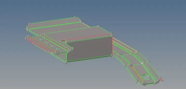
FIG1. INPUT MODEL WITH FREE EDGES
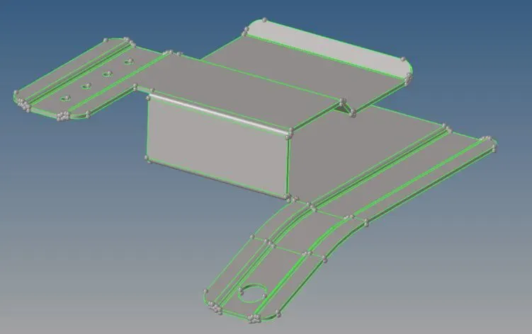
FIG2. FREE EDGES TAKEN CARE OF

FIG3. MIDSURFACE OF THE MODEL
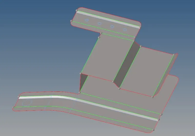
FIG4. GEOMETRY CLEAN-UP
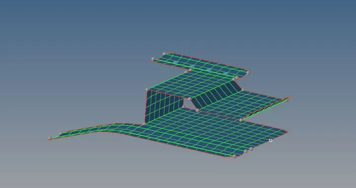
FIG5. MESHED MODEL WITH NO ELEMENTS FAILING
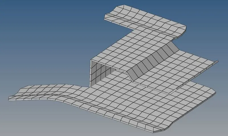
FIG6. ASSIGNED THICKNESS
PART-2
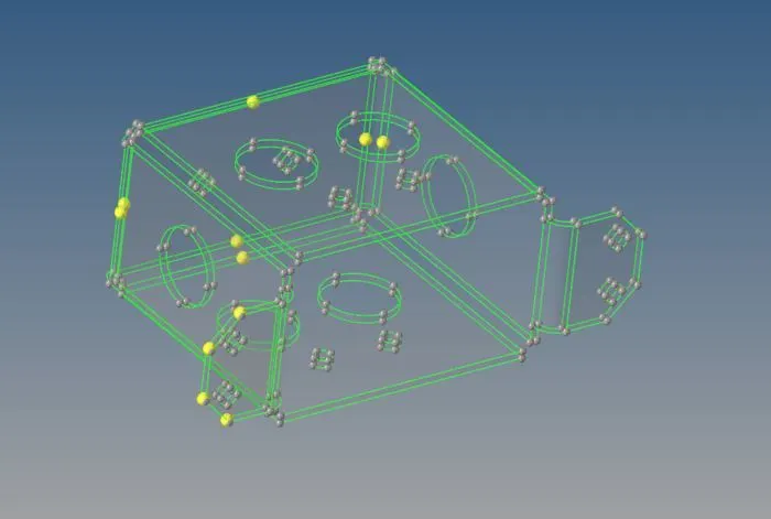
FIG7. INPUT MODEL OF PART-2
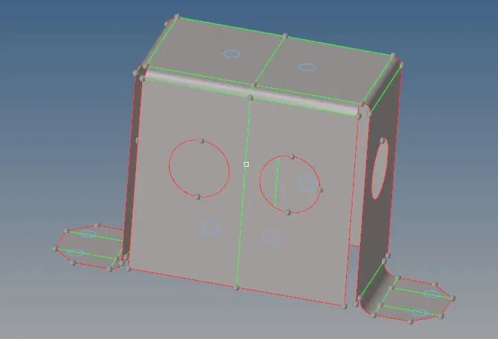
FIG8. EXTRACTED MIDSURFACE AND GEOMETRY CLEANED-UP
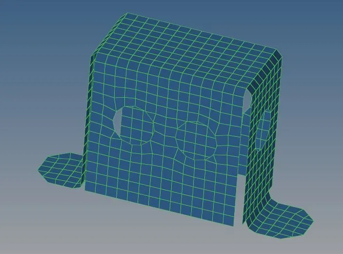
FIG9. MESHED MODEL WITH NO ELEMENT FAILING
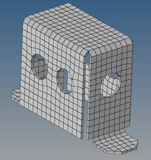
FIG10. MESH WITH ASSIGNED THICKNESS
PART-3:
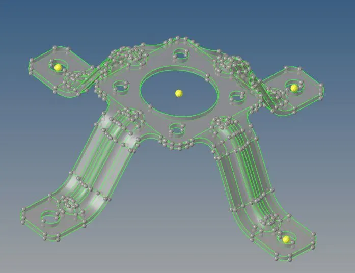
FIG11. INPUT MODEL OF PART-2
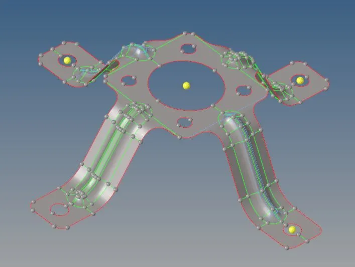
FIG12. EXTRACTED MIDSURFACE AND GEOMETRY CLEANED-UP
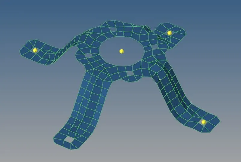
FIG13. MESHED MODEL WITH NO ELEMENT FAILING
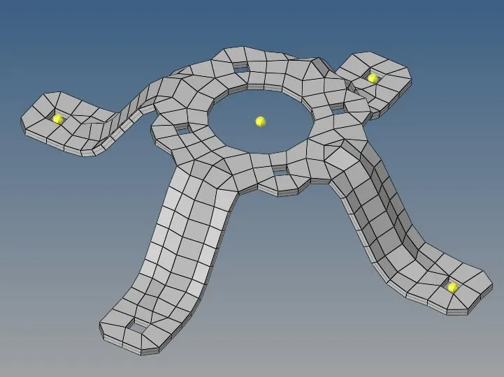
FIG14. MESH WITH ASSIGNED THICKNESS
CONCLUSION: In this project, I have applied all my knowledge to mesh the given components with proper mesh flow and mesh quality.