1D Element Creation in HypereWorks
ELEMENT CREATION
OBJECTIVE: To create various 1D elements like rod, beam, bar, mass and spring with given cross sections.
ABSTRACT: Nodes and Elements are the very backbones of Finite Element Analysis. In FEA, we divide our model into small pieces. Those are called Finite Elements (FE). Those Elements connect all characteristic points, called Nodes that lie on their circumference. This “connection” is a set of equations called shape functions. Each FE has its own set of shape functions that connect all of the Nodes of that Element. Adjacent Elements share common Nodes (the ones on the shared edge). This means that shape functions of all the Elements in the model are “tied” thanks to those common nodes. In this challenge, I have created 1D element on a given model of bracket. This report contains the procedure to create those elements and theory related to it.
PROBLEM STATEMENT:
- Create mesh with 5units size.
- Create 1D element with given cross section and dof.
- Rod element: Translational Dof constrained with Rb2 links. Cross section: box. Dimensions: a=12mm, b=10mm and t=0.75mm
- Beam element: All Dof constrained with Rbe3 links. Cross section: I. Dimensions: a=8mm, b=10mm, c=8.5mm, t1= 0.75mm, t2= 0.6mm and t3=0.6mm.
- Bar element: X and Y Dof constrained with Rbe3 links. Cross section: X. Dimensions: Dim1=5mm, Dim2=1.2mm, Dim3=10mm, Dim4= 1.2mm.
- At d and e: Rbe2 links. Apply mass of magnitude 10.
- At f: Join components with spring elements.
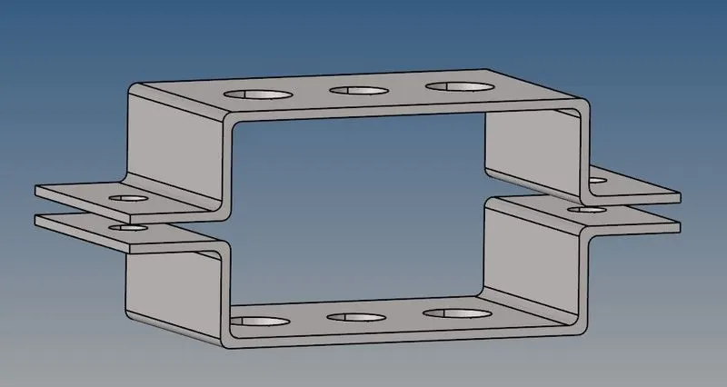
FIG. INPUT MODEL
THEORY:
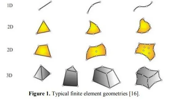
ELEMENTS: Every small part after we dissect the model into finite piece is called element. Elements, in general, are grouped into 1D, 2D and 3D elements depending on their shape. The simplest element is created using 2 nodes that is a line which is 1D element. Other examples of 1D elements are truss elements, beam elements, rod elements etc.
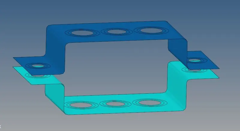
MIDSURFACE: Midsurface modeling is a technique for creating a simplified shell representation of a solid model. Midsurface modeling can reduce the computational expense of analyzing a complete solid model when a shell model with a defined thickness and fewer details is suitable for the required analysis. Midsurface modeling is best suited to thin solids or thin-walled solids where wall thickness is constant or where reasonable approximations of the wall thickness at each point can be made easily.
RBE2 AND RBE3 ELEMENTS:
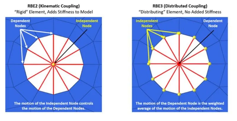
A multipoint constraint is a type of Finite Element which allows a relationship to be defined between several nodes simultaneously. Commonly referred to as MPC’s, these elements allow constraints to be imposed between different degrees of freedom of the model and can be used to simulate a wide range of physical phenomena, including nonlinear and non-homogeneous behavior. Most often, though, MPC’s are used to represent more basic interactions: rigid connections and distributed connections, known respectively as RBE2’s and RBE3’s (or Kinematic Couplings and Distributed Couplings).
- RBE2 elements add infinite stiffness to the nodes being constrained
- RBE3 elements provide a distributed connection, which does not influence the local (or global) stiffness of the model.
ROD, BAR AND BEAM:
A rod and Bar are subjected to Axial load only, this can be either tensile or compressive but not torsion or bending. Moreover, a bar is suitable for symmetrical sections only. And a Beam can be subjected to any type of load, tension compression, torsion and bending, shear etc. So if we have a bar or rod subjected to tension and u added a bending moment on it then this will no more called as a bar, now it has become a beam.
SOLUTION:
Creating Midsurface:
- Open the given model. Import geometry and select IGES option.
- Once the model is imported, clean the lines which are present in the model as these are not required.
- Create midsurface for the upper bracket from Geometry< midsurface< select the upper bracket. Rename this component as bracket_1.
- As the model contain 2 brackets and we need 2 midsurfaces separately to give different thickness to both of them, create a component and rename it as bracket_2. Now repeat the step 3 for lower bracket.
- If we observe under component tab, we can see a midsurface which we must move into bracket_2. Go to tools< organize< select midsurface< move.
- Delete all the unnecessary components like solid model because these are not needed henceforth. We now have only 2 components.
Creating material, properties for brackets and assigning them:
- Right click under model view and create material. Rename it as steel and let the card image as MAT1 as of now.
- Right click and create property. Rename this as bracket_1 and let card image be PSHELL and assign material as steel and thickness of 0.
- Right click and create property. Rename this as bracket_2 and let the card image be PSHELL and assign material as steel and thickness of 5.
- Click on bracket_1 component and assign material as steel and bracket_1 property. Similarly for bracket_2 component assign bracket_2 property.
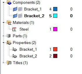
Creating mesh of size 5 units: we are creating mesh as it will be easier to choose the nodes and make elements.
- Go to geometry< quick edit< washer split and create washer splits of 5 units for every holes.
- Go to 2D< automesh select size as 5units and mixed elements and mesh all components.
- Now as the mesh is created we should refine it a little bit by increasing and matching the number of nodes at holes and washer split.
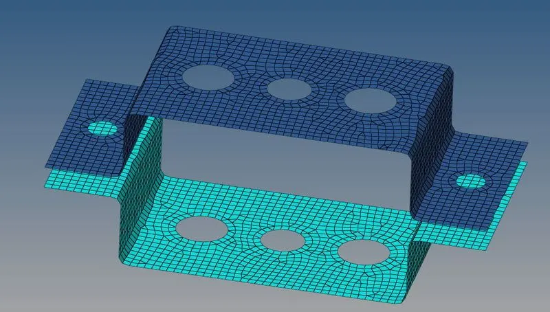
Creating rbe2 and rbe3 links:
General procedure to create both the links is:
- Go to 1D< rigids (rbe2)< select calculate nodes< multiple nodes< select required nodes< select dof< create.
- Go to 1D< rbe3 < select required nodes< select dof< create.
The problem statement provides different situations for creating all the links. So according to the question, only thing that we should change is dof in every case. Dof1 Dof2 Dof3 represent translation motion in x,y and z axes and Dof4, Dof5 and Dof6 represent rotational motion in x,y and z axes.
- For a: un-tick dof 4, 5, 6 in Rbe2 element.
- For b: tick everything in Rbe3 element.
- For c: un-tick dof 3 and 6 in Rbe3 element.
- For d: nothing is specified so tick everything in Rbe2 element.

FIG. FOR A
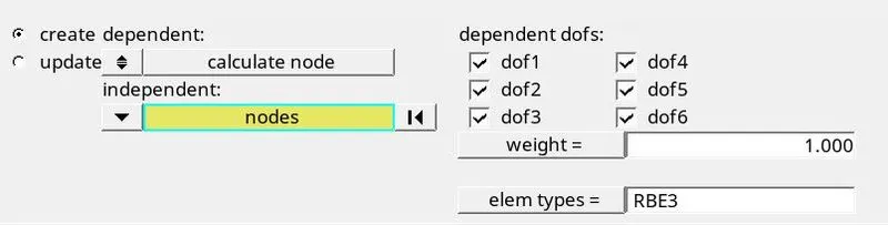
FIG. FOR B
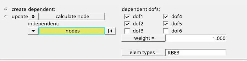
FIG. FOR C
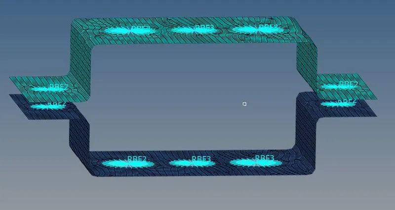
FIG. RBE2 AND RBE3 LINKS
Creating mass elements:
Go to 1D< masses< element type: Cmass1< mass: 10 units< select the nodes at specified location< create
Creating spring elements:
To create spring elements exactly at the centre of the sides we must create nodes.
- Go to geometry< nodes< interpolate nodes. Create 4 nodes on 4 edges of the midsurface. These 4 nodes will be in the centre of the respective edges.
- Go to 1D< springs. Select 2 nodes on the same side (vertical to each other) and create a spring element.
- Repeat the procedure for the other side.
Creating rod, beam and bar cross section:
- Go to 1D< Hyperbeam< select thinwalled box< create.
- A new window will open with cross section of thinwalled box for a. Give dimensions as mentioned in the problem that is a=12mm, b=10mm and t=0.75mm.
- Right click< create< standard section< Hypermesh< standard I section (for b).
- An I section will be created. Edit the dimension according to the question that is a=8mm, b=10mm, c=8.5mm, t1= 0.75mm, t2= 0.6mm and t3=0.6mm.
- Right click< create< standard section< Optistruct< Cross (for c).
- A plus or cross will be created. Change the dimensions according to the problem statement that is Dim1=5mm, Dim2=1.2mm, Dim3=10mm, Dim4= 1.2mm.
- Thus all the cross sections are created. Rename them as rod, beam and bar to avoid confusion later and switch to model view.
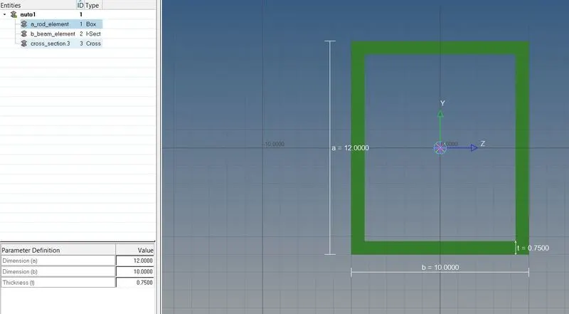
FIG. CROSS SECTION OF THIN WALLED BOX
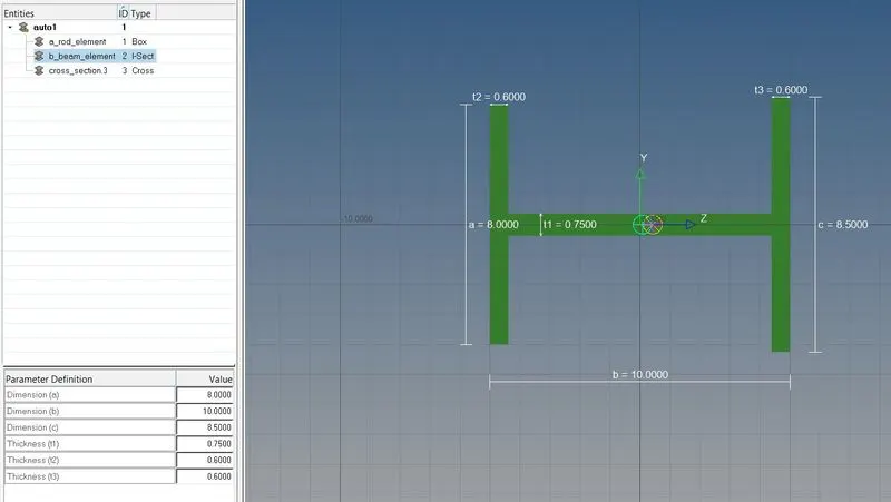
FIG. CROSS SECTION OF I BEAM
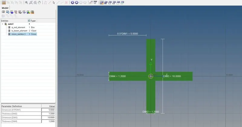
FIG. CROSS SECTION OF CROSS BEAM
Creating properties for rod beam and bar elements:
- Right click< create< property. Repeat this 3 times and rename these 3 properties as rod, beam and bar.
- Select rod and change its card image to PROD and assign beam section: rod (cross section which was renamed as rod).
- Select beam and change its card image to PBEAM and assign beam section: beam.
- Select bar and change its card image to PBAR and assign beam section: bar.
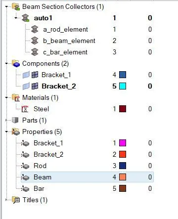
Creating rod, beam and bar elements:
- Go to 1D< rods< create. Select the nodes at position a where we made rbe2 links and assign element type: CROD and property: Rod (created in the above step) and create a rod element at a.
- Go to 1D< bars< create. Select the nodes at position b where we created rbe3 elements and assign element type: CMBEAM and property: Beam and create a beam element at b.
- Go to 1D< bars< create. Select the nodes at position c where we created rbe3 elements and assign element type: CBAR and property: Bar and create a bar element at c.
- Change 1D traditional element representation to 1D detailed element representation to view elements created in detailed view.
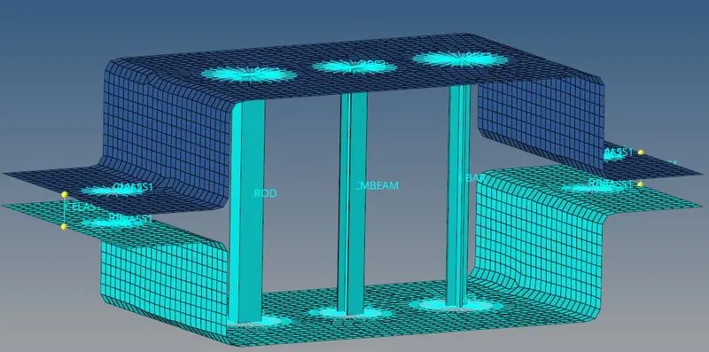
FIG. FINAL MODEL
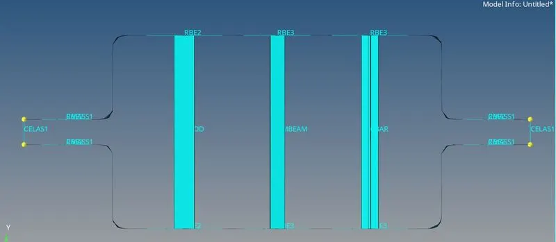
FIG. FINAL MODEL SHOWING EVERY ELEMENTS
CONCLUSION: We have studied to make 1D element and created it successfully as a part of challenge.