Design of Clamp Unit & Pin-Clamp Unit
DESIGN OF CLAMP UNIT AND PIN-CLAMP UNIT
OBJECTIVE: To design 3 types of Swivel Clamp unit and 1 Pin-Clamp unit with different Riser, Blade and Clamp arm while maintaining the stroke of cylinder as 100mm.
ABSTRACT: In automotive industry, a lot of processes are followed to make a single panel and further operations are performed on that panel and other panels to get an automobile. The role of BIW fixture design engineer is to make fixtures for the panels so that they can be worked on. A fixture is a work holding device that holds support and locates the work piece in a desired position to perform any operation. For automotive industry, a fixture is an assembly of different units like rest pin units, fixed pin units, retractable pin units, Clamp unit, rough locator units, sensor units, base unit etc. In this project, I have focused on designing Swivel Clamp units and Pin-Clamp unit. This report touches on the introduction of fixtures, explanation of 3-2-1 principle, basic definitions and explanation of and related to the clamp unit and its parts, tools used while working, methodology and other necessary explanations.
SOFTWARE USED: CATIA V5
WORKBENCH USED:
- Sketcher workbench
- Part workbench
- Assembly workbench
TOOLS USED:
- Sketching tools
- Translational tools
- Pad
- Hole
- Manipulation tool
- Snap and smart move tool
INTRODUCTION
FIXTURE: A fixture is a work holding device that holds support and locates the work piece in a desired position to perform any operation. This is the main purpose of the fixture that is to hold and support the work piece during machining operation and to provide repeatability, accuracy and interchangeability in the manufacturing of the products.
CLAMP UNIT IN BIW FIXTURE: A clamp unit is used to hold the panel at desired location and prevent it from unnecessary movements. A clamp plan is provided by the customer, which helps us to design the clamp unit as it consists of the location of clamping. But to understand how the clamp unit successfully restricts the movement of the panel we must understand 3-2-1 principle.
The 3-2-1 Principle states that the six locators are sufficient to restrict the required degree of freedom of any work piece. In this, motion is restricted using clamps and locators. A three-pin base can restrict five motions and six pins restrict nine motions.
Let us understand this in detail. When any work piece is not clamped or held, it can move or rotate in any direction and along any axis. We can list its movements as:
- Translational motion along x-axis.
- Translational motion along y-axis.
- Translational motion along z-axis.
- Rotational motion along x-axis.
- Rotational motion along y-axis.
- Rotational motion along y-axis.
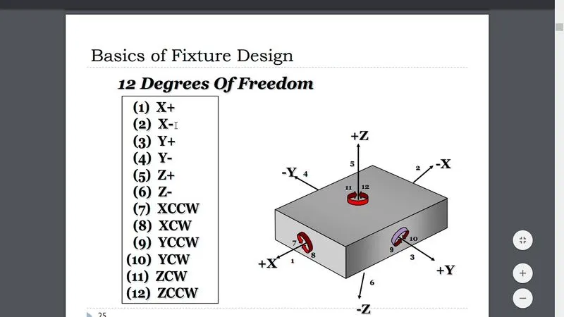
FIG. DEGREES OF FREEDOM
These are not just 6 but 12 as its motion will be along positive and negative directions and along clockwise and counter clockwise direction. But if we were to perform any operation on that work piece we must restrict the movements in order to perform the task without any mistakes. This can be achieved by 3-2-1 principle. In 3-2-1 principle we make use of locating pins in the given order to fix it on a fixture:
- 3 pins are located on the bottom side of the component. These pins constrain the translational motion of the body in z direction and rotational motion along x-axis and y-axis. Thus 3 degrees are restricted. But the body still can rotate along z-axis and translate in x-axis and y-axis.
- 2 pins are located on the back side of the component. These pins constrain the translational motion along x-axis and rotational motion along z-axis. Thus we have constrained 5 degrees in total. But translation along y-axis is still possible.
- 1 pin located on the adjacent side of the 2 pins we can constrain the last degree that is translation along y-axis.
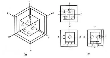
FIG. LOCATING PINS
In clamp unit, we use clamping Mylar and Rest Mylar to locate the panel. Here we are doing following things:
- Restricting the upward and downward motion that is movement along z-axis.
- Restricting clockwise and counter clockwise rotation along x-axis.
- Restricting clockwise and counter clockwise rotation along y-axis.
Thus out of 6, we are restricting 3 degrees of freedom when we clamp the panel. Similarly, when we locate the panel with locating pins we:
- Restrict the translational movement along x-axis.
- Restrict the translational movement along y-axis.
- Restrict the rotational movement along x-axis.
- Restrict the rotational movement along y-axis.
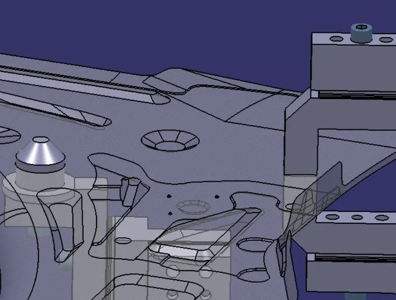
FIG. LOCATING PIN AND CLAMPING
COMPONENTS OF SWIVEL CLAMP UNIT:
- NC blocks
- Clamp arm
- Swivel cylinder
- Stopper
- Blade
- Riser
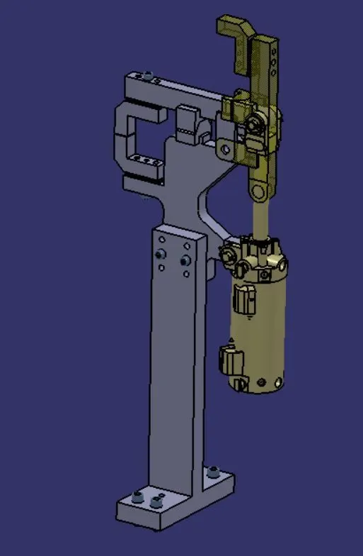
FIG. SWIVEL CLAMP UNIT
COMPONENTS OF PIN-CLAMP UNIT:
- NC blocks
- Clamp arm
- Swivel cylinder
- Stopper
- Pin
- Pin retainer
- L-block
- Blade
- Riser
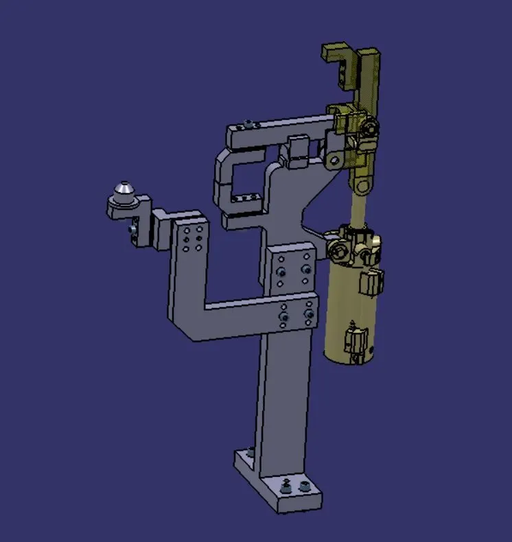
FIG. PIN-CLAMP UNIT
Locating pins: They are used for controlled, fine tolerance positioning of a work piece. For example, a pallet that is moved along one axis, where the drive mechanism is not accurate and stable enough to place it in a position sufficiently accurate to execute a particular process, the use of locating pins may be the best solution. Usually two locating pins are enough to properly locate the work piece on one plane. We should also consider the following points while choosing the locating pins:
- Pin should engage 3-5mm from car part entry surface.
- All pins should be accommodated with 2-way adjustable shims irrespective of direction of arresting.
- Round pins should be used in case of 4-way arresting of car part if the hole is round.
- Round pins can be used in 2-way arresting of car part if the hole is slotted.
- Diamond pins should be used in case of 4-way arresting of car part if the hole is slotted.
- Diamond pins can be used in 2-way arresting of car part if the hole is round.
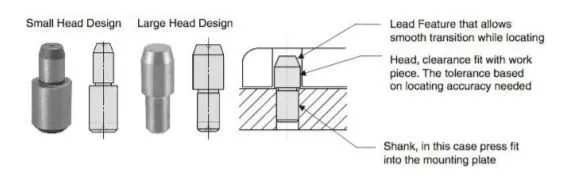
FIG. DIFFERENT PINS
The Diamond Shape is a critical feature that helps with machining inaccuracies and smoother locating operation. When two round head pins are installed onto one plate, the distance between two mounting holes must be extremely precise and even then, the work piece will not be placed on the base as easily as it would with the use of a diamond shape pin.
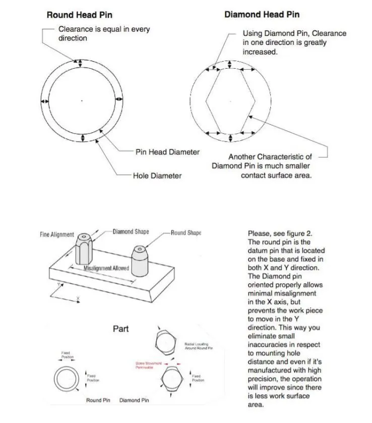
FIG. DIAMOND HEAD AND ROUND HEAD PIN
Typically, locating pins are manufactured from hardened tool steel such as O1 heat treated to 60-63Rc or from case hardened carbon steel (1045 with 45-50Rc). In some cases, soft 300 series or hardened 400 stainless is used in assemblies where no rust is accepted. Please, remember that pins made out of soft materials will wear out much faster than harden pins.
There is a variety of coatings that can be chosen based on your application. In corrosive environments, a hard chrome, Dicoat or TiCN coatings can help extend the life of the pin since they provide non-corrosive and hard layer that can be as hard as 3000 Vickers. A variety of insulating coatings or materials can be used in case of welding applications. KCF stainless steel coat is one surface treatment that provides great insulation and prevents weld build-up between the work piece and the surface of the pin.
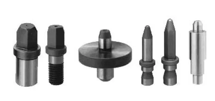
FIG. DIFFERENT TYPES OF PINS
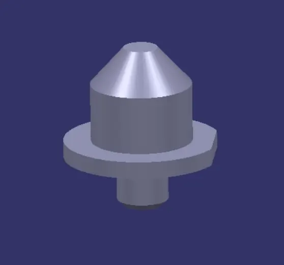
FIG. PIN DESIGNED FOR THE PROJECT
Pin retainer: A pin retainer is a part which holds the pin in position. It can either be a make part or a standard part. Pin retainers can be of two types:
HORIZONTAL PIN RETAINERS: Horizontal pin retainers are used to extend a straight plane with a perpendicular locating pin. These come with either 3 or 4 hole configuration with tapped and untapped hole variations. All the locating pin hole for horizontal pin retainers are 16mm in diameter.
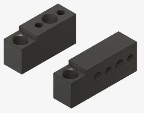
FIG. HORIZONTAL PIN RETAINER
VERTICAL PIN RETAINERS: Vertical pin retainers help to extend plane while placing the locating pin parallel to the original plane and block. Pin holes are bored to 16mm in diameter.
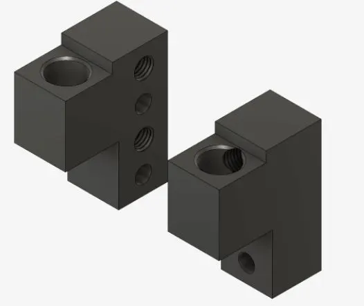
FIG. VERTICAL PIN RETAINER
A standard pin retainer NAAMS APR050 is shown below:
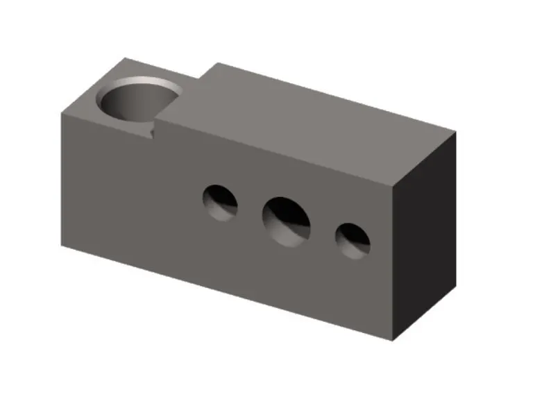
FIG. NAAMS APR050 PIN RETAINER
Usually the material used for making pin retainer is Steel / ASTM A-36.
Following things are kept in mind while making a pin retainer:
- Pin retainer should have a hole with a fit on which the pin will be fixed.
- The pin mounting surface of the pin retainer should be a fine machined surface.
- The pin mounting surface of the pin retainer should have a step to lock the rotation of the pin.
- The mounting surface of the pin retainer to the blocks should be a machined surface.
- The pin retainer will be fixed to a block or a L-block to the riser with 2 dowel holes and at least with one screw hole to maintain the tolerance.
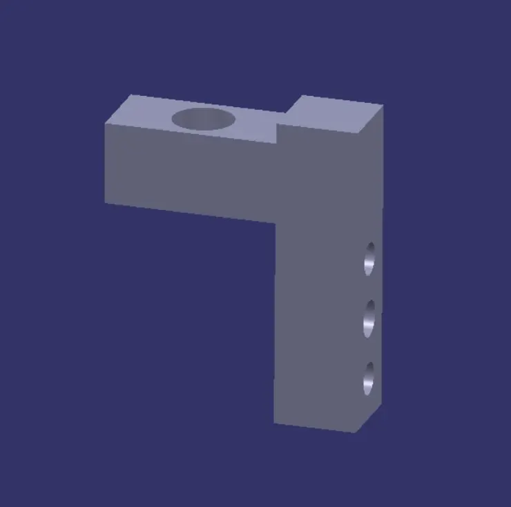
FIG. PIN RETAINER DESIGNED FOR THE PROJECT
Block/L-block:
- These parts are mainly used to accommodate the shimming direction as per fundamental in general.
- In some cases they are used for other design feasibility.
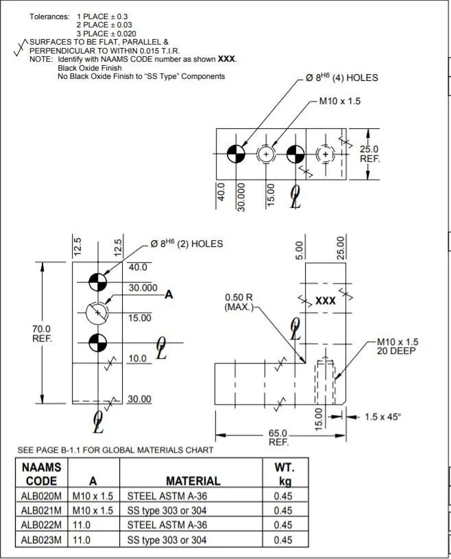
FIG. STANDARD L-BLOCK
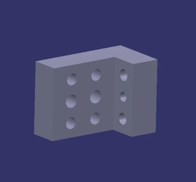
FIG. L-BLOCK DESIGNED FOR THE PROJECT
Blade:
- Blades are the plates which are attached to the riser and other components like cylinder, arm etc are mounted on it.
- It can either be a standard part or a make part.
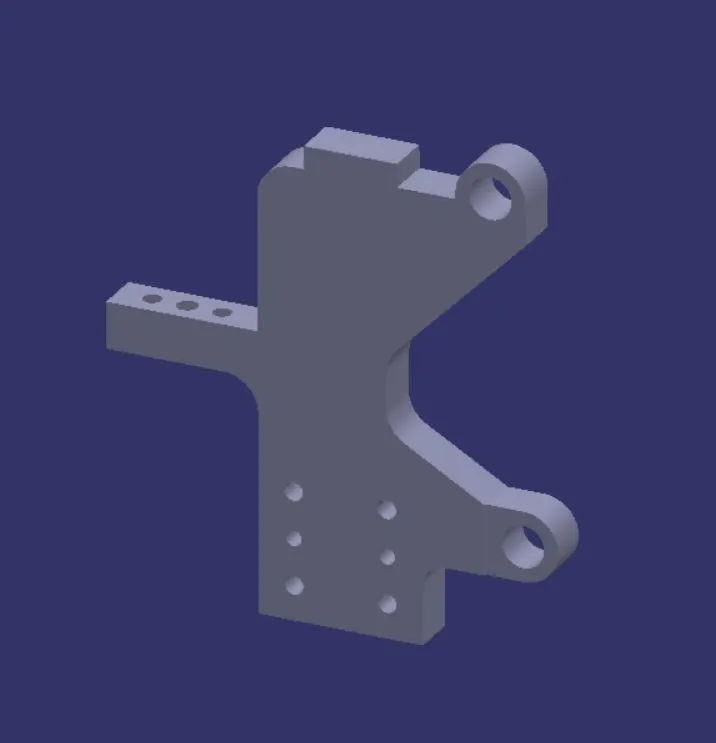
FIG. BLADE DESIGNED FOR THE PROJECT
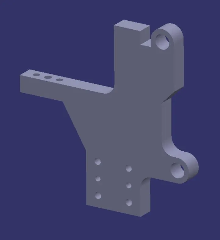
FIG. BLADE DESIGNED FOR THE PROJECT
Riser:
- Riser is a structure generally used to mount the toggle clamp and rest, clamp Mylar and location pin and to give height to the assembly.
- It is not necessary to have one riser where all the parts of clamp or rest or location units are mounted.
- Generally risers are either made of plate fabrication or plate and tube welding together or from single gas cut plate.
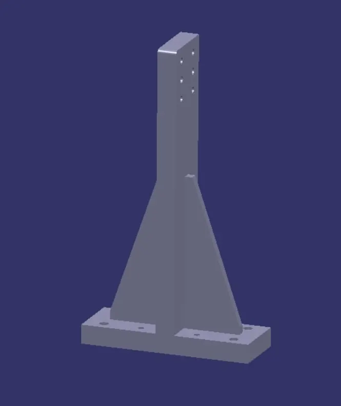
FIG. RISER DESIGNED FOR THE PROJECT
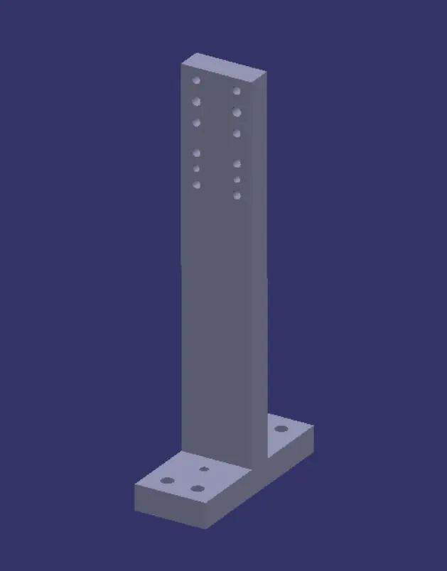
FIG. RISER DESIGNED FOR THE PROJECT
NC block/Mylar:
- NC blocks or popularly also known as Mylar is the ones which hold the panel.
- It prevents the panel from deforming while welding.
- They always come in pairs.
- Top Mylar is known as clamping Mylar and bottom Mylar is known as resting Mylar.
Few points to remember about Mylar:
- Generally Mylar clamping block clamp cross section (the area which in contact panel) is considered as 20mmx20mm.
- Most of the OEM's /Tier 1 prefer Mylar to have 5mm allowance material for machining. Most of Mylar are CNC machined if it is clamping 3D profile.
- Depending on the angle of cross section, Mylar will be having shimming either in one direction or in 2 directions. General Thumb rule is if the section is inclined more than 15 deg or clamping surface is 3D profile then 2 direction shimming is provided. The reason being simple mathematics. Equation of inclined line/ plane will be having 2 parameters to controls and we control with shimming in 2 directions. Less than 15 deg does not mean that there are not 2 parameters. These are their but they are neglected if angle is less than 15 deg.
- Clamping or holding of Mylar depend upon various OEM or Tier 1 stand. Various options are available. 2 screws and 2 dowel OR 1 screw and 2 dowels. Size of dowel or screw selected as per the customer input or existing experience. Mostly M10 screw, Diameter 8mm dowel or M8 and Diameter 6mm dowels are selected.
- Tolerance of dowel is made as per the customer or Tier 1 guidelines. Keep simple rule in mind, if you are removing Mylar then should have loose /sliding fit. D10 or F8 depending upon guidelines.
- Mylar’s material can be C45, Teflon, Aluminum or S-Grun as per the customer requirement. Generally, S-Grun Mylar are made of more thickness.
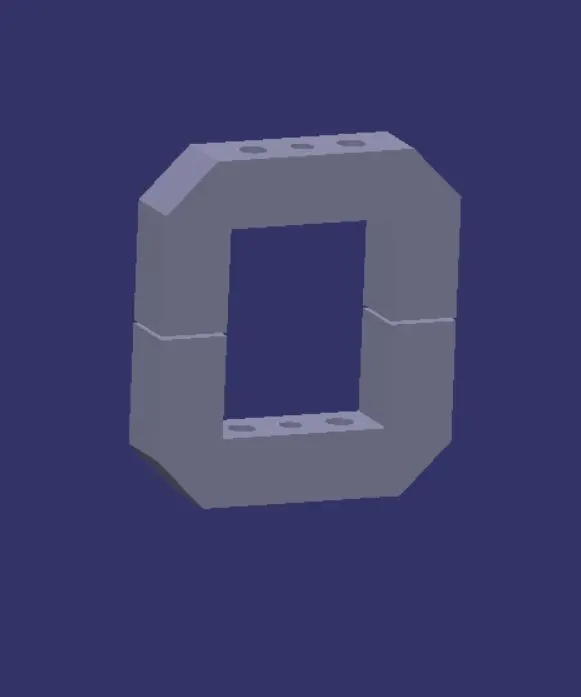
FIG. MYLAR DESIGNED FOR THE PROJECT
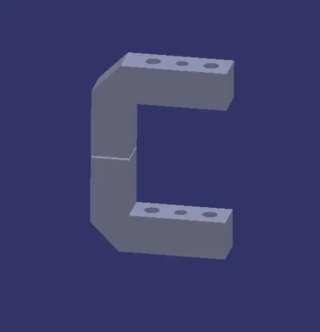
FIG. MYLAR DESIGNED FOR THE PROJECT
Shim:
- Shimsare washers or thin strips of material used to align parts, make them fit or reduce wear.
- Shims are designed to fit in between blocks and fixtures to provide support or reach a dimension required in the assembly.
- Typically designed in a U shape matter so that they can fit between mounting screws. This shape helps to make them easy to install and remove or replace.
- Designers will use shims individually or as packs of 5, 6, or 7 pieces. Thicknesses range from 0.25mm to 2mm.
- Many assemblies require a tolerance to be hit in relation to a length or height; shims allow designers to hit these tolerances. They can be stacked between NAAMS NC blocks, L blocks, or pin retainers.
- They come in a variety of sizes and styles. The material is typically very thin so that they can accommodate smaller to larger tolerances.
- NAAMS specification for the material is an SAE cold rolled steel.
- Different widths of the shims can have different surface treatments either yellow zinc dichromate, black oxide, or none. Yellow zinc dichromate surface treatment is used for corrosive resistance and acts as an anti-rust primer. Black oxide coating is also for corrosion resistance.
- Generally shim is used as a pack with 2*0.5mm, 2*1mm, 2mm shims.
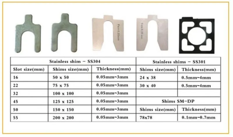
FIG. STANDARD SHIM
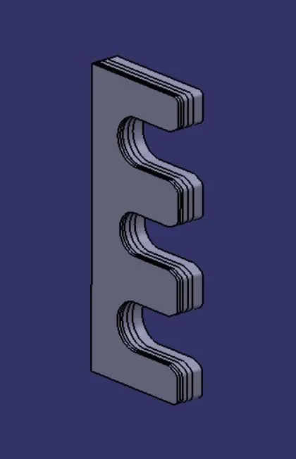
FIG. SHIM PACK DESIGNED FOR THE PROJECT
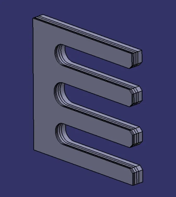
FIG. SHIM PACK DESIGNED FOR THE PROJECT
Clamp arm:
- It is a device that mounts on the swivel cylinder and attaches to the clamp Mylar.
- The clamp arm is used to open and close the clamp unit.
- This can be a standard part or make part. In this project I have designed same type of clamp arm with varying lengths.
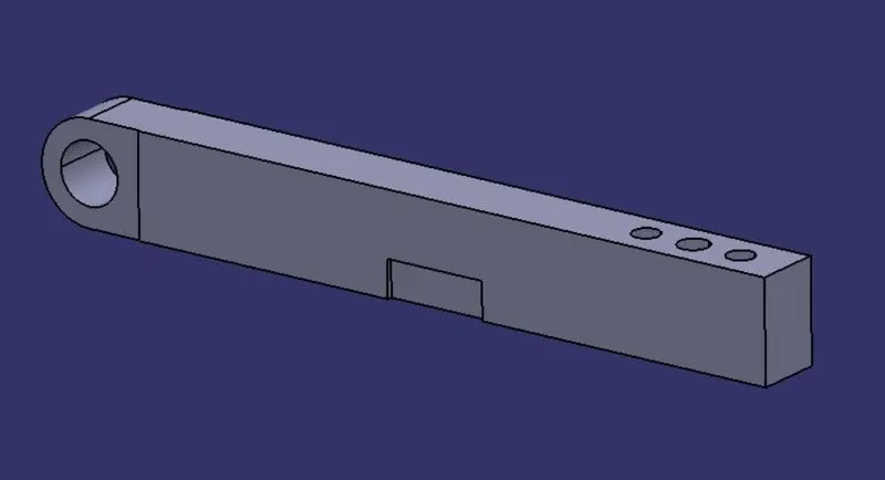
FIG. CLAMP ARM DESIGNED FOR THE PROJECT
Standard parts: While designing, a designer must use standard parts wherever he can to reduce the cost and time for manufacturing the component. In this project I have used following standard parts:
- Fasteners
- Swivel cylinder
Fasteners: For this project ISO 4762 Hexagonal socket head cap screw were used with varying diameter and length. Mostly M8 screws with varying lengths are used but to fasten the riser to the base plate M10 or M12 are used. The length varies with respect to the thickness of the part that is to be fastened. This length is calculated by the formula:
Length of the screw= 1.5d+ distance between the start of surfaces to be fastened
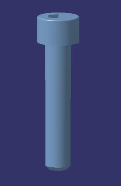
FIG. ISO 4762 Hexagonal socket head cap screw
Swivel cylinder: For this project I have used Clevis clamp cylinder.
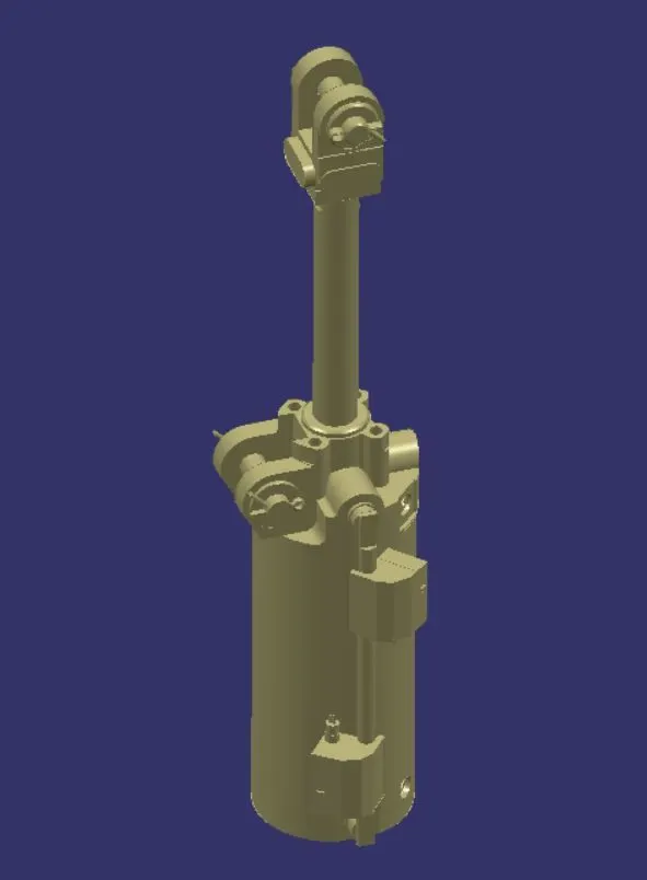
FIG. CELVIS CYLINDER
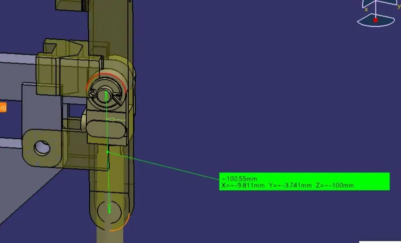
FIG. STROKE OF 100MM
FINAL MODEL:
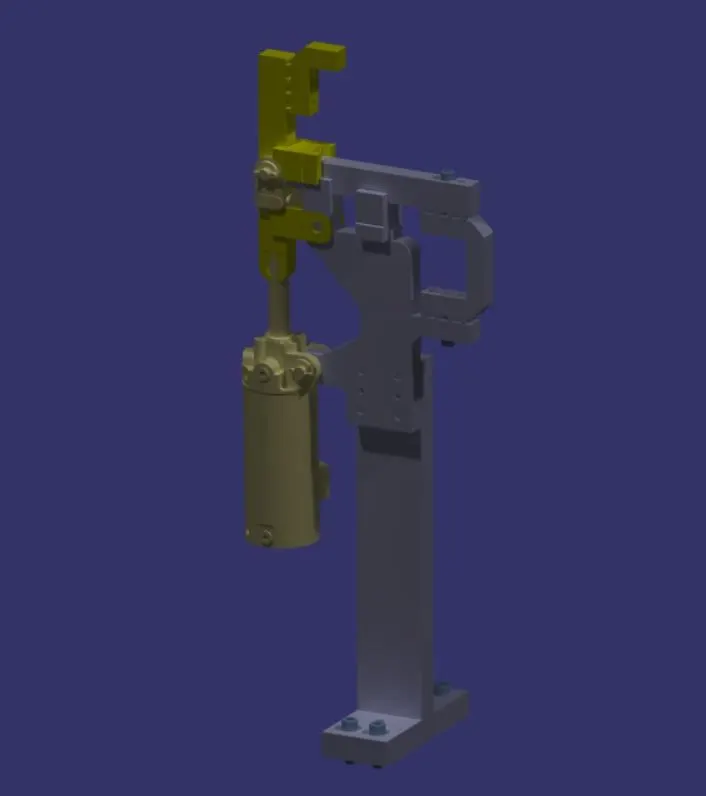
FIG. SWIVEL CLAMP UNIT 1
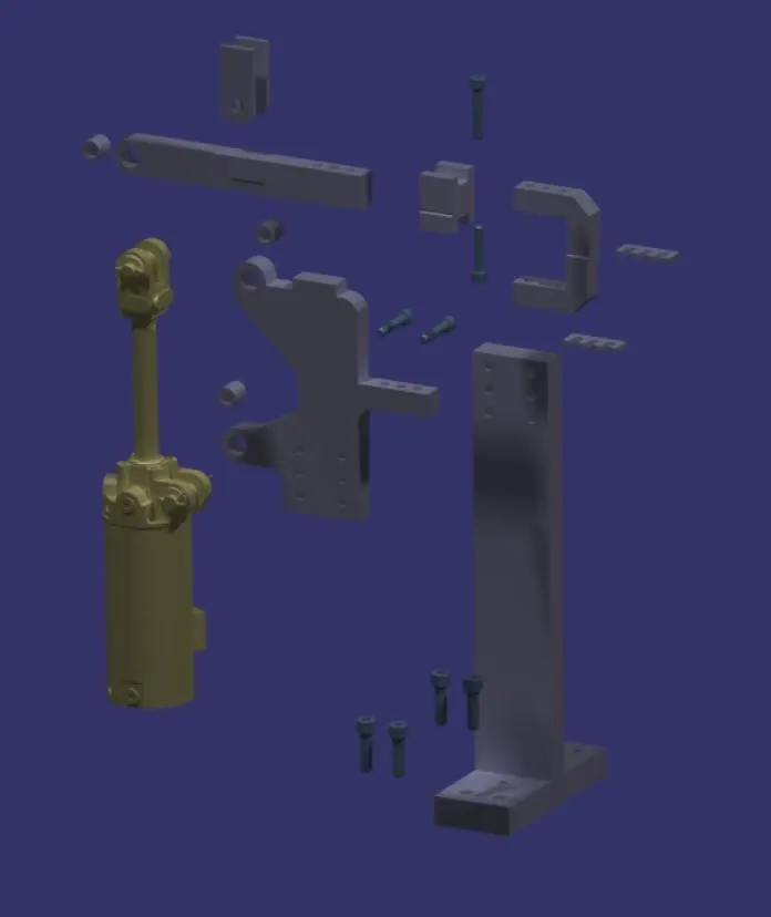
FIG. EXPLODED VIEW OF SWIVEL CLAMP UNIT 1
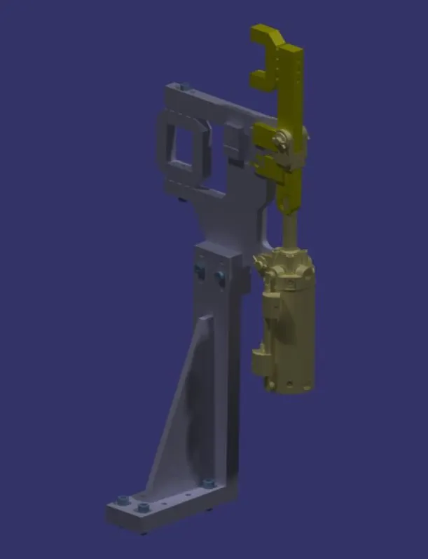
FIG. SWIVEL CLAMP UNIT 2
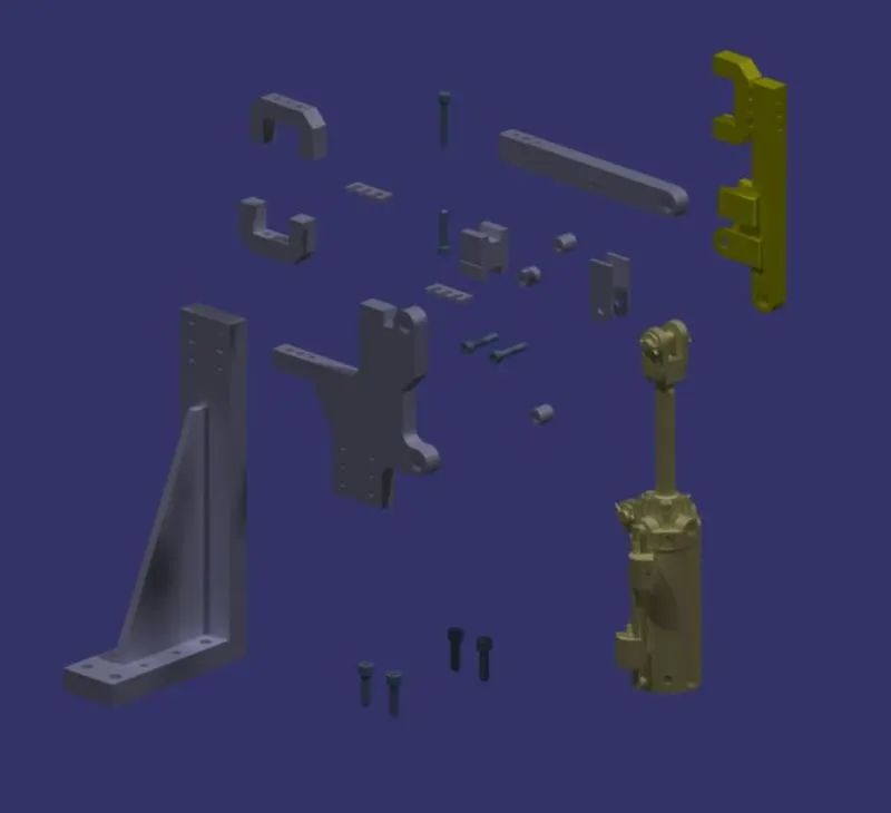
FIG. EXPLODED VIEW OF SWIVEL CLAMP UNIT 2
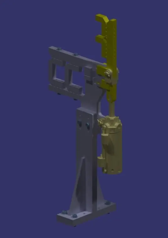
FIG. SWIVEL CLAMP UNIT 3
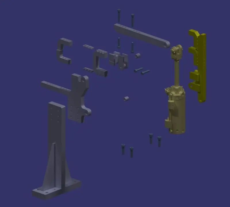
FIG. EXPLODED VIEW OF SWIVEL CLAMP UNIT 3
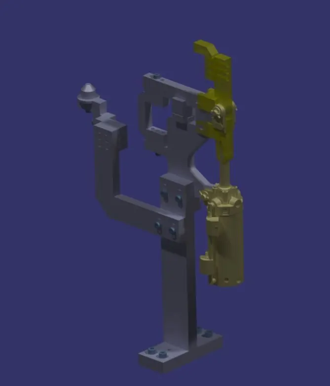
FIG. PIN-CLAMP UNIT
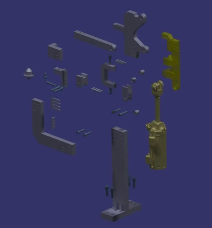
FIG. EXPLODED VIEW OF PIN-CLAMP UNIT
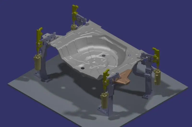
FIG. ASSEMBLY OF FINAL MODEL
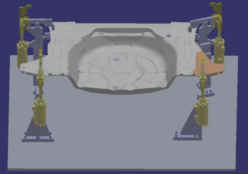
FIG. ASSEMBLY OF FINAL MODEL
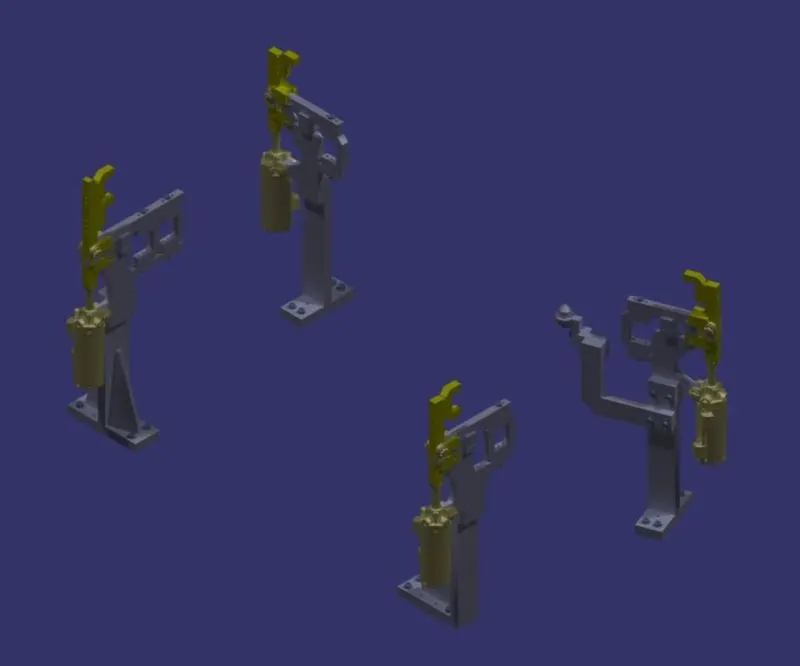
FIG. CLAMP UNITS WITHOUT PANEL